

- •Foreword
- •Preface
- •Is This Book for You?
- •How This Book Is Organized
- •How to Use This Book
- •Doing the Exercises
- •Conventions Used in This Book
- •What the Icons Mean
- •About the CD-ROM
- •Other Information
- •Contacting the Author
- •Acknowledgments
- •Contents at a Glance
- •Contents
- •Getting Acquainted with AutoCAD and AutoCAD LT
- •Starting AutoCAD and AutoCAD LT
- •Creating a New Drawing
- •Using the AutoCAD and AutoCAD LT Interface
- •Creating Your First Drawing
- •Saving a Drawing
- •Summary
- •Creating a New Drawing from a Template
- •Working with Templates
- •Opening a Drawing with Default Settings
- •Opening an Existing Drawing
- •Using an Existing Drawing as a Prototype
- •Saving a Drawing Under a New Name
- •Summary
- •The Command Line
- •Command Techniques
- •Of Mice and Pucks
- •Getting Help
- •Summary
- •Typing Coordinates
- •Displaying Coordinates
- •Picking Coordinates on the Screen
- •Locating Points
- •Summary
- •Unit Types
- •Drawing Limits
- •Understanding Scales
- •Inserting a Title Block
- •Common Setup Options
- •The MVSETUP Command
- •Summary
- •Using the LINE Command
- •Drawing Rectangles
- •Drawing Polygons
- •Creating Construction Lines
- •Creating Rays
- •Summary
- •Drawing Circles
- •Drawing Arcs
- •Creating Ellipses and Elliptical Arcs
- •Making Donuts
- •Placing Points
- •Summary
- •Panning
- •The ZOOM Command
- •Aerial View
- •Named Views
- •Tiled Viewports
- •Snap Rotation
- •User Coordinate Systems
- •Isometric Drawing
- •Summary
- •Editing a Drawing
- •Selecting Objects
- •Summary
- •Copying and Moving Objects
- •Using Construction Commands
- •Creating a Revision Cloud
- •Hiding Objects with a Wipeout
- •Double-Clicking to Edit Objects
- •Grips
- •Editing with the Properties Palette
- •Selection Filters
- •Groups
- •Summary
- •Working with Layers
- •Changing Object Color, Linetype, and Lineweight
- •Working with Linetype Scales
- •Importing Layers and Linetypes from Other Drawings
- •Matching Properties
- •Summary
- •Drawing-Level Information
- •Object-Level Information
- •Measurement Commands
- •AutoCAD’s Calculator
- •Summary
- •Creating Single-Line Text
- •Understanding Text Styles
- •Creating Multiline Text
- •Creating Tables
- •Inserting Fields
- •Managing Text
- •Finding Text in Your Drawing
- •Checking Your Spelling
- •Summary
- •Working with Dimensions
- •Drawing Linear Dimensions
- •Drawing Aligned Dimensions
- •Creating Baseline and Continued Dimensions
- •Dimensioning Arcs and Circles
- •Dimensioning Angles
- •Creating Ordinate Dimensions
- •Drawing Leaders
- •Using Quick Dimension
- •Editing Dimensions
- •Summary
- •Understanding Dimension Styles
- •Defining a New Dimension Style
- •Changing Dimension Styles
- •Creating Geometric Tolerances
- •Summary
- •Creating and Editing Polylines
- •Drawing and Editing Splines
- •Creating Regions
- •Creating Boundaries
- •Creating Hatches
- •Creating and Editing Multilines
- •Creating Dlines
- •Using the SKETCH Command
- •Digitizing Drawings with the TABLET Command
- •Summary
- •Preparing a Drawing for Plotting or Printing
- •Creating a Layout in Paper Space
- •Working with Plot Styles
- •Plotting a Drawing
- •Summary
- •Combining Objects into Blocks
- •Inserting Blocks and Files into Drawings
- •Managing Blocks
- •Using Windows Features
- •Working with Attributes
- •Summary
- •Understanding External References
- •Editing an Xref within Your Drawing
- •Controlling Xref Display
- •Managing Xrefs
- •Summary
- •Preparing for Database Connectivity
- •Connecting to Your Database
- •Linking Data to Drawing Objects
- •Creating Labels
- •Querying with the Query Editor
- •Working with Query Files
- •Summary
- •Working with 3D Coordinates
- •Using Elevation and Thickness
- •Working with the User Coordinate System
- •Summary
- •Working with the Standard Viewpoints
- •Using DDVPOINT
- •Working with the Tripod and Compass
- •Getting a Quick Plan View
- •Shading Your Drawing
- •Using 3D Orbit
- •Using Tiled Viewports
- •Defining a Perspective View
- •Laying Out 3D Drawings
- •Summary
- •Drawing Surfaces with 3DFACE
- •Drawing Surfaces with PFACE
- •Creating Polygon Meshes with 3DMESH
- •Drawing Standard 3D Shapes
- •Drawing a Revolved Surface
- •Drawing an Extruded Surface
- •Drawing Ruled Surfaces
- •Drawing Edge Surfaces
- •Summary
- •Drawing Standard Shapes
- •Creating Extruded Solids
- •Drawing Revolved Solids
- •Creating Complex Solids
- •Sectioning and Slicing Solids
- •Using Editing Commands in 3D
- •Editing Solids
- •Listing Solid Properties
- •Summary
- •Understanding Rendering
- •Creating Lights
- •Creating Scenes
- •Working with Materials
- •Using Backgrounds
- •Doing the Final Render
- •Summary
- •Accessing Drawing Components with the DesignCenter
- •Accessing Drawing Content with Tool Palettes
- •Setting Standards for Drawings
- •Organizing Your Drawings
- •Working with Sheet Sets
- •Maintaining Security
- •Keeping Track of Referenced Files
- •Handling Errors and Crashes
- •Managing Drawings from Prior Releases
- •Summary
- •Importing and Exporting Other File Formats
- •Working with Raster Images
- •Pasting, Linking, and Embedding Objects
- •Summary
- •Sending Drawings
- •Opening Drawings from the Web
- •Creating Object Hyperlinks
- •Publishing Drawings
- •Summary
- •Working with Customizable Files
- •Creating Keyboard Shortcuts for Commands
- •Customizing Toolbars
- •Customizing Tool Palettes
- •Summary
- •Creating Macros with Script Files
- •Creating Slide Shows
- •Creating Slide Libraries
- •Summary
- •Creating Linetypes
- •Creating Hatch Patterns
- •Summary
- •Creating Shapes
- •Creating Fonts
- •Summary
- •Working with Menu Files
- •Customizing a Menu
- •Summary
- •Introducing Visual LISP
- •Getting Help in Visual LISP
- •Working with AutoLISP Expressions
- •Using AutoLISP on the Command Line
- •Creating AutoLISP Files
- •Summary
- •Creating Variables
- •Working with AutoCAD Commands
- •Working with Lists
- •Setting Conditions
- •Managing Drawing Objects
- •Getting Input from the User
- •Putting on the Finishing Touches
- •Summary
- •Understanding Local and Global Variables
- •Working with Visual LISP ActiveX Functions
- •Debugging Code
- •Summary
- •Starting to Work with VBA
- •Writing VBA Code
- •Getting User Input
- •Creating Dialog Boxes
- •Modifying Objects
- •Debugging and Trapping Errors
- •Moving to Advanced Programming
- •A Final Word
- •Installing AutoCAD and AutoCAD LT
- •Configuring AutoCAD
- •Starting AutoCAD Your Way
- •Configuring a Plotter
- •System Requirements
- •Using the CD with Microsoft Windows
- •What’s on the CD
- •Troubleshooting
- •Index

Chapter 24 Creating Solids and Editing in 3D |
715 |
Using Editing Commands in 3D
When you draw in 3D, you need to edit your models either to make corrections or as part of the construction process. A number of editing commands are exclusively for 3D or have special 3D options. In this section, you explore these special commands and options. Table 24-2 lists most of the regular editing commands and how they’re used in 3D drawings.
You can use grips on 3D objects, although it’s sometimes difficult to visualize in which plane you’re moving or stretching an object. You cannot stretch solids, but you can stretch surfaces and wireframes. (If you try to stretch a solid, AutoCAD just moves it.)
Mirroring in 3D
If the mirror line is on the XY plane, you can mirror any 3D object with the regular MIRROR command. If you want to mirror in any other plane, use MIRROR3D.
To use MIRROR3D, follow these steps:
1.Choose Modify 3D Operation Mirror 3D.
2.Select the object or objects you want to mirror.
3.At the Specify first point of mirror plane (3 points) or [Object/Last/ Zaxis/View/XY/YZ/ZX/3points] <3points>: prompt, choose one of the options to define the mirroring plane. These are the same options described in Table 24-1 for the SECTION command. The only additional option is Last, which uses the last defined mirroring plane.
4.At the Delete source objects? [Yes/No] <N>: prompt, press Enter to keep the original objects or right-click and choose Yes to delete them.
|
Table 24-2: Editing Commands in 3D |
|
|
Command |
Use in 3D Drawings |
|
|
ERASE |
Same as for 2D. |
COPY |
Same as for 2D. |
MIRROR |
Can be used on 3D objects as long as the mirror line is in the XY plane. Otherwise, |
|
use MIRROR3D. |
OFFSET |
Can be used in 3D space but only on 2D objects. |
ARRAY |
Can be used on 3D objects in the XY plane. Otherwise, use 3DARRAY. |
MOVE |
Same as for 2D. |
ROTATE |
Can be used on 3D objects in the XY plane. Otherwise, use ROTATE3D. |
SCALE |
Can be used on 3D objects. Scales all three dimensions. |
STRETCH |
Can be used in 3D space but only on 2D objects, wireframes, and surfaces. The |
|
results may not be what you expect because it is hard to visualize the direction of |
|
the stretch. |
Continued

716 Part IV Drawing in Three Dimensions
|
|
|
Table 24-2 (continued) |
|
|
|
|
|
|
Command |
Use in 3D Drawings |
|
|
|
|
|
|
LENGTHEN |
Can be used in 3D space but only on 2D objects. |
|
|
TRIM |
Has special options for 3D but only works on 2D objects, such as lines. |
|
|
EXTEND |
Has special options for 3D but only works on 2D objects, such as lines. |
|
|
BREAK |
Can be used in 3D space but only on 2D objects. |
|
|
CHAMFER |
Has special options for 3D. |
|
|
FILLET |
Has special options for 3D. |
|
|
EXPLODE |
Works on 3D objects — solids explode to surfaces, and surfaces explode to |
|
|
|
wireframes. You can also explode blocks containing 3D objects. |
|
|
ALIGN |
Works on 3D objects. |
|
|
|
|
On the |
The drawing used in the following Step-by-Step exercise on mirroring in 3D, ab24-4.dwg, is |
||
CD-ROM |
in the Results folder on the CD-ROM. |
||
STEP-BY-STEP: Mirroring in 3D
1.If you have ab24-04.dwg open from the previous exercise, use it. Do a regen to remove the hidden view. If you don’t have it open, open it from your AutoCAD Bible folder or from the Results folder of the CD-ROM. Make sure OSNAP is on and set a running object snap for endpoint. If you don’t have the Solids Editing toolbar open, right-click any toolbar and choose Solids Editing from the toolbar list. The drawing is shown in Figure 24-25.
3
2
1
Figure 24-25: This 3D model was sliced and can now be mirrored.
2. Save your drawing as ab24-05.dwg in your AutoCAD Bible folder.

Chapter 24 Creating Solids and Editing in 3D |
717 |
3.Choose Modify 3D Operation Mirror 3D. Follow the prompts:
Select objects: Select the solid. Right-click to end object selection.
Specify first point of mirror plane (3 points) or [Object/Last/Zaxis/View/XY/YZ/ZX/3points] <3points>: Pick 1 in Figure 24-25.
Specify second point on mirror plane: Pick 2. Specify third point on mirror plane: Pick 3.
Delete source objects? [Yes/No] <N>: Right-click and choose Enter.
4.Choose Union on the Solids Editing toolbar. Select both solids. Right-click to end object selection. AutoCAD unites them.
5.Save your drawing.
Arraying in 3D
You can array any 3D object using the ARRAY command as long as you define the array in the current XY plane. The 3DARRAY command enables you to create a rectangular array with the normal rows and columns but adding levels in the Z direction. For a 3D polar array, you define an axis of rotation instead of the 2D point used in the ARRAY command.
Creating 3D rectangular arrays
The rectangular array is the most common type of array. A 3D rectangular array has rows, columns, and levels. To create a 3D rectangular array, follow these steps:
On the
CD-ROM
1.Choose Modify 3D Operation 3D Array to start the 3DARRAY command.
2.Select the objects you want to array.
3.At the Enter the type of array [Rectangular/Polar] <R>: prompt, right-click and choose Rectangular.
4.At the Enter the number of rows (---) <1>: prompt, type the total number of rows you want. Rows are parallel to the X axis.
5. At the Enter the number of columns (|||) <1>: prompt, type the total number of columns you want. Columns are parallel to the Y axis.
6.At the Enter the number of levels (...) <1>: prompt, type the total number of levels you want. Levels are parallel to the Z axis.
7. At the Specify the distance between rows (---): prompt, type a unit distance or pick two points.
8.At the Specify the distance between columns (|||): prompt, type a unit distance or pick two points.
9. At the Specify the distance between levels (...): prompt, type a unit distance or pick two points.
The drawing used in the following Step-by-Step exercise on creating a rectangular array in 3D, ab24-c.dwg, is in the Drawings folder on the CD-ROM.
718 Part IV Drawing in Three Dimensions
STEP-BY-STEP: Creating a Rectangular Array in 3D
1.Open ab24-c.dwg from the CD-ROM.
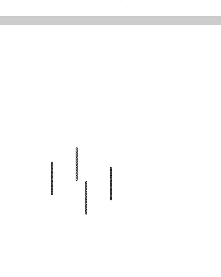
2.Save the file as ab24-06.dwg in your AutoCAD Bible folder. This is a drawing showing a sphere, a bead-like shape sometimes used for table legs. In this exercise, you create a 3D rectangular array to create four table legs.
3.Choose Modify 3D Operation 3D Array. Follow the prompts:
Select objects: Select the bead. Right-click to end object selection.
Enter the type of array [Rectangular/Polar] <R>: Right-click and
choose Rectangular.
Enter the number of rows (---) <1>: 2 Enter the number of columns (|||) <1>: 2
Enter the number of levels (...) <1>: 20 (The bead is 1.5 inches
high and the leg should be 30 inches high.)
Specify the distance between rows (---): 26 (This is the narrower
distance between the legs.)
Specify the distance between columns (|||): 36 (This is the wider
distance between the legs.)
Specify the distance between levels (...): 1.5 (You want the beads to touch along the leg.)
4.Do a Zoom Extents to see the result. (Now you would create the tabletop.)
5.Save your drawing. It should look like Figure 24-26.
Figure 24-26: The four legs of a table, created by using a 3D rectangular array.
Creating 3D polar arrays
Polar arrays are not as common as rectangular arrays, either in 2D or in 3D, but in the right circumstances can make your work a lot easier. Instead of using a center point as you do in a 2D polar array, you define a center axis. To create a 3D polar array, follow these steps:

Chapter 24 Creating Solids and Editing in 3D |
719 |
1.Choose Modify 3D Operation 3D Array to start the 3DARRAY command.
2.Select the objects you want to array.
3.At the Enter the type of array [Rectangular/Polar] <R>: prompt, right-click and choose Polar.
4. At the Enter the number of items in the array: prompt, type the total number of items you want.
5.At the Specify the angle to fill (+=ccw, -=cw) <360>: prompt, press Enter to array around a full circle or type any lesser angle.
6.At the Rotate arrayed objects? [Yes/No] <Y>: prompt, press Enter to accept the default or type n if you don’t want to rotate the objects as they’re arrayed.
7.At the Specify center point of array: prompt, specify the center point of the array. This is also the first point of the axis of rotation.
8.At the Specify second point on axis of rotation: prompt, specify any other point on the axis of rotation.
If you rotate less than a full circle, you need to determine the positive angle of rotation. The positive direction of the axis goes from the first point you specify (the center point) to the second point. Point your right thumb in the positive direction and follow the curl of the fingers of that hand to determine the positive angle of rotation.
On the |
The drawing used in the following Step-by-Step exercise on creating 3D polar arrays, |
CD-ROM |
ab24-d.dwg, is in the Drawings folder on the CD-ROM. |
STEP-BY-STEP: Creating 3D Polar Arrays
1.Open ab24-d.dwg from the CD-ROM.
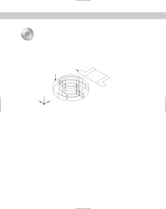
2.Save the file as ab24-07.dwg in your AutoCAD Bible folder. You see part of a lamp, as shown in Figure 24-27. Make sure OSNAP is on. Set a running object snap for endpoint.
3.To array the bracket that supports the lampshade, choose Modify 3D Operation 3D Array. Follow the prompts:
Select objects: Select the support at 1 in Figure 24-27.
Select objects: Right-click.
Enter the type of array [Rectangular/Polar] <R>: Right-click and
choose Polar.
Enter the number of items in the array: 3 Specify the angle to fill (+=ccw, -=cw) <360>: Rotate arrayed objects? [Yes/No] <Y>:
Specify center point of array: Pick the endpoint at 2.
Specify second point on axis of rotation: Pick the endpoint at 3.
4.One of the three supports cannot be seen in this view. To see all three, choose View 3D Orbit. From inside the arcball, click and drag down a bit until you can see all three supports.
5.Choose View 3D Views Top to return to plan view and save your drawing.
720 Part IV Drawing in Three Dimensions
Figure 24-27: A partially completed lamp.
2 1
3
Rotating in 3D
You can rotate 3D objects in the XY plane with the ROTATE command. Use ROTATE3D when you need to rotate objects in any other plane. The ROTATE3D options are shown in Table 24-3.
|
Table 24-3: ROTATE3D Options |
|
|
Option |
Description |
|
|
Object |
Enables you to choose a line, circle, arc, or 2D polyline. If you choose a circle or arc, |
|
AutoCAD rotates around a line that starts at the object’s center and extends perpendicular |
|
to the object’s plane. |
Last |
Uses the last defined axis of rotation. |
View |
Defines the axis of rotation parallel to the current view at the intersection of a point you |
|
specify. |
Xaxis |
The axis of rotation is parallel to the X axis and passes through a point you specify. |
Yaxis |
The axis of rotation is parallel to the Y axis and passes through a point you specify. |
Zaxis |
The axis of rotation is parallel to the Z axis and passes through a point you specify. |
2points |
This is the default. Specify two points to define the axis. It’s a good idea to use object |
|
snaps. |
|
|
Tip |
Sometimes creating an object in the XY plane and then rotating it afterward is easier. In other |
|
words, you may create an object in the wrong plane on purpose and use ROTATE3D later to |
|
properly place it. |
Chapter 24 Creating Solids and Editing in 3D |
721 |
To use ROTATE3D, follow these steps:
1.Choose Modify 3D Operation Rotate 3D.
2.Select the object or objects you want to rotate.
3.At the Specify first point on axis or define axis by [Object/Last/ View/Xaxis/Yaxis/Zaxis/2points]: prompt, select one of the options explained in Table 24-3, and define the axis according to the option prompts.
4.At the Specify rotation angle or [Reference]: prompt, specify a positive or negative rotation angle or choose the Reference option. (The Reference option works like the Reference option for ROTATE. See Chapter 9.)
You need to determine the positive direction of rotation. Point your right thumb in the positive direction of the axis and follow the curl of your fingers. If you pick two points, the positive direction of the axis goes from the first pick point to the second pick point.
On the |
The drawing used in the following Step-by-Step exercise on rotating in 3D, ab24-e.dwg, is |
CD-ROM |
in the Drawings folder on the CD-ROM. |
STEP-BY-STEP: Rotating in 3D
1.Open ab24-e.dwg from the CD-ROM.
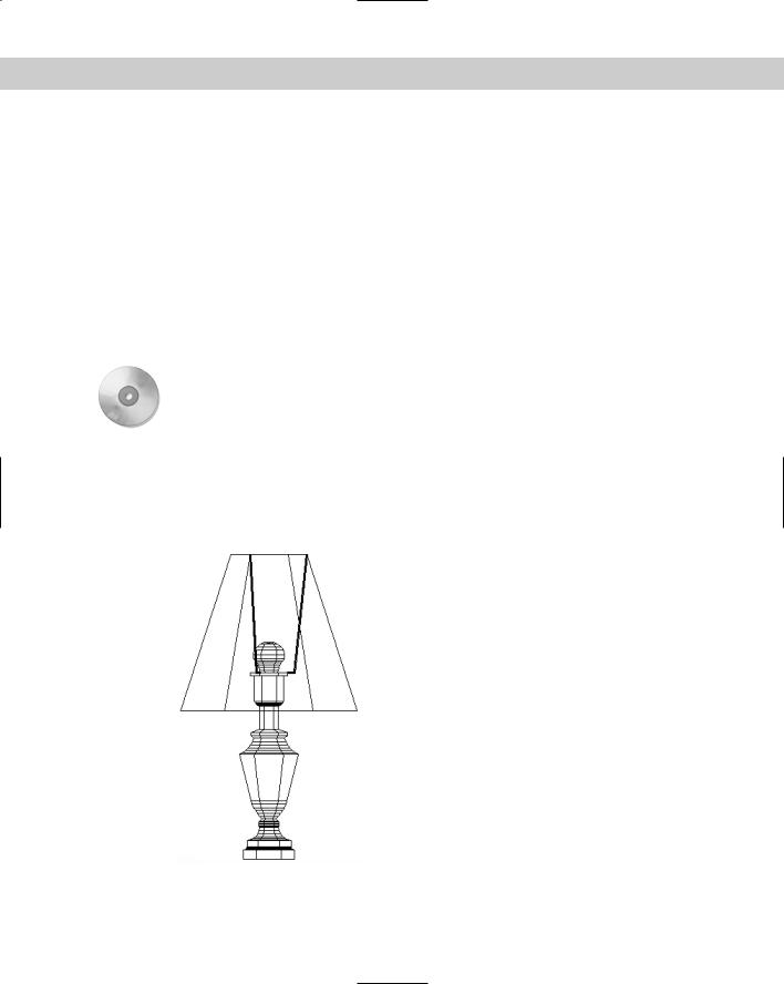
2.Save the file as ab24-08.dwg in your AutoCAD Bible folder. You see the same lamp used in the previous Step-by-Step exercise, but it has now been completed, as shown in Figure 24-28.
Figure 24-28: The completed lamp.

722 Part IV Drawing in Three Dimensions
3.To insert the lamp in a plan view drawing of a house, you need to see it in plan view from the WCS. In other words, you should be looking down at the lamp. To do this, you need to rotate the lamp around the X axis. To visualize this, look at the UCS icon and imagine rotating the top of the lamp toward you around the horizontal (X) axis. To rotate the lamp, choose Modify 3D Operation Rotate 3D. Follow the prompts:
Select objects: Start a crossing window to select the entire lamp. Other corner: Pick the other corner.
Select objects: Right-click.
Specify first point on axis or define axis by [Object/Last/View/ Xaxis/Yaxis/Zaxis/2points]: Right-click and choose Xaxis.
Specify a point on the X axis <0,0,0>: Right-click. Specify rotation angle or [Reference]: 90
4.Choose Zoom Extents from the Zoom flyout of the Standard toolbar to see the entire lamp. The lamp is now rotated 90 degrees around the X axis in relation to the UCS, and you’re looking at it from the top.
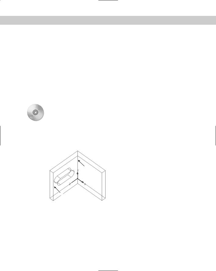
5.To get a better view, choose View 3D Views SE Isometric. Use the HIDE command to hide the drawing. It should look like Figure 24-29. Of course, looking at the lamp from a different viewpoint does not change the orientation of the lamp relative to the UCS.
Figure 24-29: The lamp is now ready to place in a 3D drawing of a house.
6. Save your drawing.
Aligning in 3D
I have already covered the ALIGN command in Chapter 10. When you work in 3D, you can use the ALIGN command to move, rotate in the XY plane, and rotate in the Z direction — all in one command.
On the |
The drawing used in the following Step-by-Step exercise on aligning in 3D, ab24-f.dwg, is |
CD-ROM |
in the Drawings folder on the CD-ROM. |
Chapter 24 Creating Solids and Editing in 3D |
723 |
STEP-BY-STEP: Aligning in 3D
1.Open ab24-f.dwg from the CD-ROM.
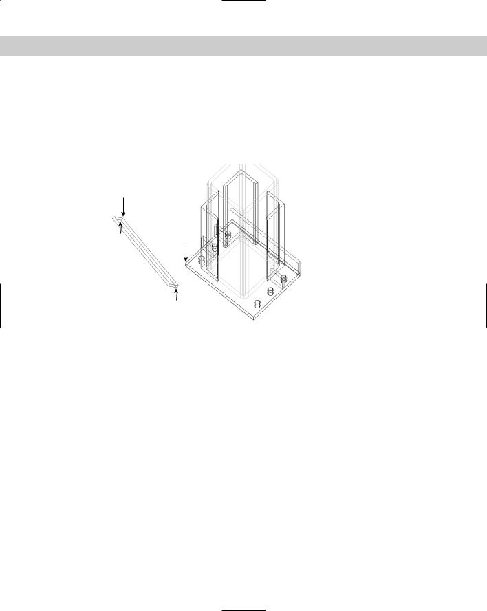
2.Save the file as ab24-09.dwg in your AutoCAD Bible folder. You see part of the base assembly for an industrial washer, as shown in Figure 24-30. One sidebar needs to be moved and rotated into place. Make sure OSNAP is on. Set a running object snap for endpoint.
2
1 3
4
 5
5
Figure 24-30: Part of a base assembly for an industrial washer with a sidebar that needs to be moved and rotated into place.
Thanks to Robert Mack of the Dexter Company, Fairfield, Iowa, for this drawing.
3.Notice that it’s hard to tell which way the sidebar is facing because it’s displayed in wireframe. Use the HIDE command to do a hide. This tells you that 1 in Figure 24-30 is facing away from you. Use the REGEN command to get back to wireframe display.
4.Choose Modify 3D Operation Align. Follow the prompts.
Select objects: Select the sidebar.
Select objects: Right-click.
Specify first source point: Pick 1 in Figure 24-30. Specify first destination point: Pick 3.
Specify second source point: Pick 4. Specify second destination point: Pick 5.
Specify third source point or <continue>: Pick 2.
Specify third destination point: Pick any point further back than 3 on the plate. The smaller bars (shown in red in the drawing) provide several endpoints that you can easily locate.
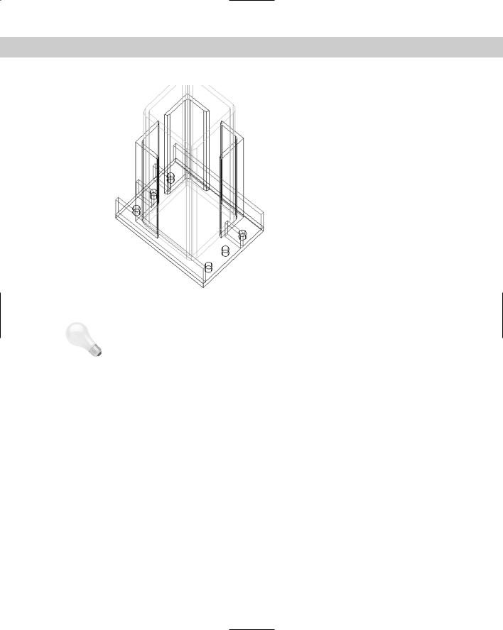
5.AutoCAD aligns the sidebar. Save your drawing. It should look like Figure 24-31.
724 Part IV Drawing in Three Dimensions
|
Figure 24-31: The sidebar has been |
|
aligned with the rest of the model. |
Tip |
The trick when aligning in 3D is to properly visualize the parts. It helps to hide the drawing |
|
first, as you did in the exercise. Also, take the time to find the UCS and a viewpoint that make |
|
the points you’re specifying easy to see and pick. |
|
Trimming and extending in 3D |
|
You can use the TRIM and EXTEND commands to trim or extend 2D objects in 3D space. |
|
AutoCAD provides the Project option for working in 3D space. The Project option has three |
|
suboptions: |
None: AutoCAD only trims or extends objects that actually intersect or can intersect in 3D space.
UCS: This is the default. AutoCAD projects objects onto the XY plane of the current UCS. Therefore, if two lines are on different Z coordinates, you can trim and extend one of them with reference to the other, even though they do not and cannot actually meet in 3D space.
View: This projects objects parallel to the current view. Objects are trimmed or extended based on the way they look on the screen. They need not (and probably won’t) actually meet in 3D space.
You can also use the Extend option to trim or extend to implied intersections, as explained in Chapter 10. In the next exercise, you practice extending objects in 3D and trimming works the same way.
Chapter 24 Creating Solids and Editing in 3D |
725 |
On the |
The drawing used in the following Step-by-Step exercise on extending objects in 3D, |
CD-ROM |
ab24-g.dwg, is in the Drawings folder on the CD-ROM. |
STEP-BY-STEP: Extending Objects in 3D
1.Open ab24-g.dwg from the CD-ROM.
2.Save the file as ab24-10.dwg in your AutoCAD Bible folder. You see a bushing, in 2D and 3D, as shown in Figure 24-32. The 3D bushing has been exploded into simple geometry — otherwise, you wouldn’t be able to use it to extend the 2D lines.
2
1
3
Figure 24-32: A bushing in 2D and 3D. The 3D bushing has been exploded but still looks the same. It can now be used to extend lines.
3.To turn the UCSORTHO system variable off, type ucsortho 0 . (If its current value is 0, just press Enter at the Enter new value for UCSORTHO <0>: prompt.)
4.Choose Extend from the Modify toolbar. Follow the prompts.
Select boundary edges ...
Select objects: Pick the 3D bushing at 1 in Figure 24-32.
Select objects: Right-click.
Select object to extend or shift-select to trim or [Project/Edge/Undo]:
Right-click and choose Project.
Enter a projection option [None/Ucs/View] <Ucs>: Right-click and choose View.
Select object to extend or shift-select to trim or [Project/Edge/Undo]:
Pick the 2D bushing at 2.
Select object to extend or shift-select to trim or [Project/Edge/Undo]:
Right-click and choose Enter.
5.Choose View 3D Views Top. You can now see that the 2D line doesn’t actually meet the 3D bushing. By using the View option, you only extended the line in that view.
6.Choose Zoom Previous from the Standard toolbar.

726 Part IV Drawing in Three Dimensions
7.Again, choose Extend from the Modify toolbar. Follow the prompts:
Select boundary edges...Select objects: Pick the bottom edge of the 3D bushing at 3.
Select objects: Right-click.
Select object to extend or shift-select to trim or [Project/Edge/Undo]:
Right-click and choose Project.
Enter a projection option [None/Ucs/View] <View>: Right-click and choose None.
Select object to extend or shift-select to trim or [Project/ Edge/Undo]: Pick the same line you picked in Step 4, but this time pick it closer to the 3D bushing, on the new length you created by extending it.
Select object to extend or shift-select to trim or [Project/Edge/Undo]:
Right-click and choose Enter.
8.Choose View 3D Views Top. You can now see that the 2D line now actually meets the 3D bushing.
9.Click Undo on the Standard toolbar twice to undo the viewpoint change and the extend operation.
10.Choose Move from the Modify toolbar. Select the entire 3D bushing. At the Specify base point or displacement: prompt, type 0,0,2 . Press Enter again to end the command. If you miss any of the objects, pick them and move them, too. This moves the entire 3D bushing 2 units in the Z direction.
11.Choose Extend from the Modify toolbar. Follow the prompts:
Select boundary edges...
Select objects: Pick the 3D bushing at 3 (the bottom ring).
Select objects: Right-click.
Select object to extend or shift-select to trim or [Project/Edge/Undo]:
Right-click and choose Project.
Enter a projection option [None/Ucs/View] <View>: Right-click and choose Ucs.
Select object to extend or shift-select to trim or [Project/Edge/Undo]:
Pick the same line you extended before, closer to its left endpoint.
Select object to extend or shift-select to trim or [Project/Edge/Undo]:
Right-click and choose Enter.
12.Choose View 3D Views Top. It looks as if the 2D line now actually meets the 3D bushing.
13.Choose View 3D Views Front. (Because UCSORTHO is off, the UCS does not change.) Now you can see that the 2D line doesn’t meet the 3D bushing.
14.Type ucsortho 1 to return UCSORTHO to its previous setting, if you changed it in Step 3.
15.Save your drawing. It should look like Figure 24-33.
Chapter 24 Creating Solids and Editing in 3D |
727 |
Figure 24-33: When you use the UCS option, the lines seem to touch the boundary edge when you look at it from the top, but they can have different Z coordinates.
Filleting in 3D
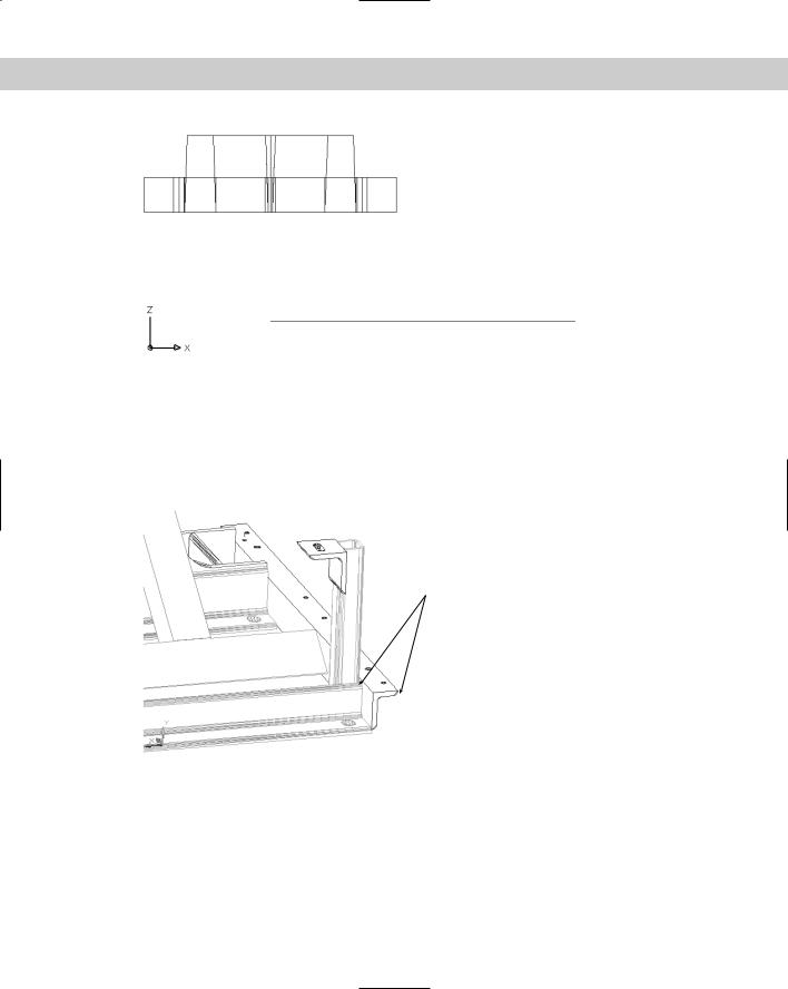
You can fillet solids but not surfaces. If you create a 3D object from lines, you can fillet the lines. Figure 24-34 shows a 3D mechanical drawing with several filleted edges.
 Filleted edges
Figure 24-34: Filleted edges are common in 3D mechanical drawings.
To use the FILLET command for solids, follow these steps:
1.Choose Fillet from the Modify toolbar.
2.At the Select first object or [Polyline/Radius/Trim/ mUltiple]: prompt, select the edge of the solid that you want to fillet. You cannot deselect this edge, so you must select the solid at the proper edge. Ignore the other options.
728 Part IV Drawing in Three Dimensions
3.AutoCAD senses that you’ve selected a solid and responds with the Enter fillet radius <0.5000>: prompt. Press Enter to accept the default of 0.5 or type a new radius.
4.At the Select an edge or [Chain/Radius]: prompt, press Enter if you only want to fillet the one edge you’ve already selected. You can also select other edges of the same solid. Press Enter to end selection of edges. AutoCAD fillets the edge or edges you selected. You can also change the Radius at this prompt.
5.Use the Chain option to fillet a set of attached edges. AutoCAD responds with the
Select an edge chain or [Edge/Radius]: prompt. Continue to pick edges that are attached to the previous edge you picked. Press Enter to end selection of edges. AutoCAD fillets the entire chain of edges.
You can select different radii for different edges. At the first Enter radius <0.5000>: prompt, specify the radius for the edge you just selected. After that, use the Radius option to set the desired radius before you select the edge.
On the |
The drawing used in the following Step-by-Step exercise on filleting solids, ab24-h.dwg, is |
CD-ROM |
in the Drawings folder on the CD-ROM. |
STEP-BY-STEP: Filleting Solids
1.Open ab24-h.dwg from the CD-ROM.
2.Save the file as ab24-11.dwg in your AutoCAD Bible folder. This is a solid model of a mounting angle, as shown in Figure 24-35. It needs to be filleted.
2
3
1
Figure 24-35: The mounting angle needs filleting.
3.Choose Fillet from the Modify toolbar.
4.At the Select first object or [Polyline/Radius/Trim/mUltiple]: prompt, pick the edge at 1 in Figure 24-35.
5.At the Enter fillet radius <0.5000>: prompt, type .25 .
6.At the Select an edge or [Chain/Radius]: prompt, pick 2.
Chapter 24 Creating Solids and Editing in 3D |
729 |
7.At the Select an edge or [Chain/Radius]: prompt, pick 3. Press Enter to end the command. AutoCAD fillets all three edges.
8.Save your drawing. It should look like Figure 24-36.
Figure 24-36: The filleted mounting angle.
Chamfering in 3D
You can chamfer solids but not surfaces. If you create a 3D object from lines, you can chamfer the lines. Figure 24-37 shows a solid with chamfered edges. (You can see this solid as part of the wheel shown at the beginning of this chapter in Figure 24-1.)
Figure 24-37: A solid with chamfered edges.
To chamfer a solid, follow these steps:
1.Choose Chamfer from the Modify toolbar.
2.At the Select first line or [Polyline/Distance/Angle/Trim/Method/ mUltiple]: prompt, select the edge you want to chamfer. The edge is displayed as a line between two surfaces. AutoCAD highlights one of the surfaces that touches the edge you selected.
730 Part IV Drawing in Three Dimensions
On the
CD-ROM
3.At the Base surface selection...Enter surface selection option [Next/OK (current)] <OK>: prompt, press Enter to accept the highlighted surface as the base surface. You need to define the base surface in case the two chamfering distances are not equal or if you want to chamfer a loop, which is the entire base surface. Right-click and choose Next to highlight the next surface. (Only two surfaces touch the edge you selected.) Press Enter when the desired surface is highlighted.
4.At the Specify base surface chamfer distance <0.5000>: prompt, type the chamfering distance for the first surface. This is the amount you want to cut off from that surface. (The default is the last distance you specified.)
5.At the Specify other surface chamfer distance <0.5000>: prompt, type the chamfering distance for the other surface. (The default is the last distance you specified.)
6.At the Select an edge or [Loop]: prompt, select the edge you want to chamfer. You can also use the Loop option. AutoCAD then prompts you to select the edge loop. Select the surface, and AutoCAD chamfers all the edges of that surface.
7.AutoCAD continues to prompt you to select edges or edge loops. Press Enter to end selection when you’re finished.
The drawing used in the following Step-by-Step exercise on chamfering solids, ab24-i.dwg, is in the Drawings folder on the CD-ROM.
STEP-BY-STEP: Chamfering Solids
1.Open ab24-i.dwg from the CD-ROM.
2.Save the file as ab24-12.dwg in your AutoCAD Bible folder. This is a simple box with dimensions of 233×102×12 millimeters, as shown in Figure 24-38.
 3
3
4
1
 2
2
Figure 24-38: You can chamfer this solid box to create a new shape.

Chapter 24 Creating Solids and Editing in 3D |
731 |
3.Choose Chamfer from the Modify toolbar. Follow the prompts:
Select first line or [Polyline/Distance/Angle/Trim/Method/mUltiple]:
Pick the edge at 1 in Figure 24-38.
Base surface selection...
Enter surface selection option [Next/OK (current)] <OK>: Specify base surface chamfer distance <0.5000>: 30 Specify other surface chamfer distance <0.5000>: 30
Select an edge or [Loop]: Pick 1. Select an edge or [Loop]:
You can’t see the chamfer because of the viewpoint. You change the viewpoint at the end of the exercise.
4.Repeat the CHAMFER command. Do the exact same operation as in Step 3, but pick 2.
5.Repeat the CHAMFER command. Follow the prompts:
Select first line or [Polyline/Distance/Angle/Trim/Method/mUltiple]:
Pick the edge at 3.
Base surface selection...
Enter surface selection option [Next/OK (current)] <OK>: Make sure the surface indicated by 4 is highlighted. If not, type n . Then
press Enter again.
Specify base surface chamfer distance <30.0000>: 233 Specify other surface chamfer distance <30.0000>: 40
Select an edge or [Loop]: Pick 3. Select an edge or [Loop]:
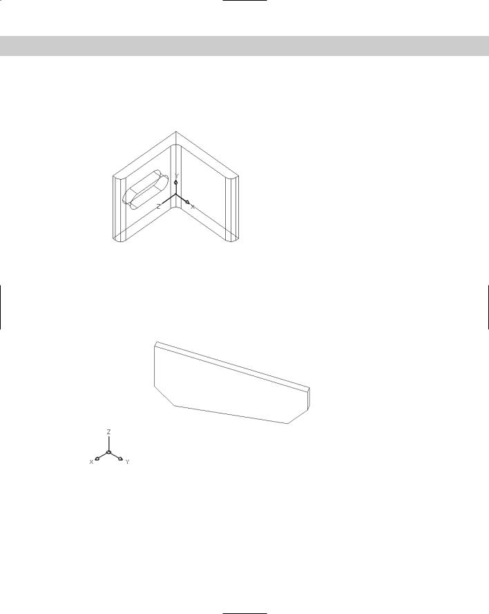
6.Choose View 3D Views Top. This shows you the shape in profile.
7.Save your drawing. It should look like Figure 24-39.
Figure 24-39: The completed solid. You can find this solid as part of Figure 24-1.