

Chapter 4 Specifying Coordinates |
59 |
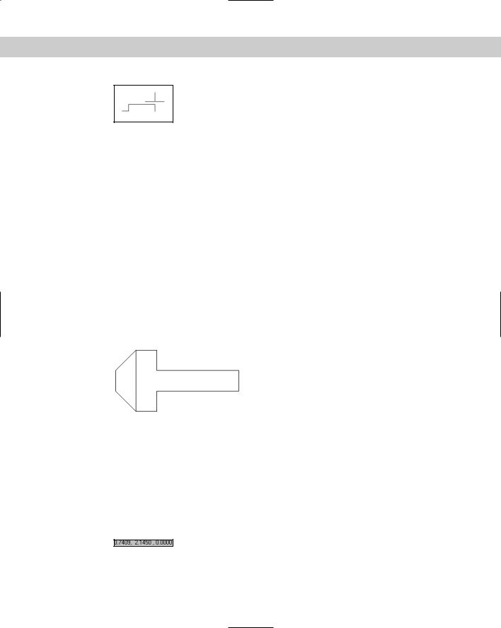
Figure 4-10: Drawing with direct distance entry enables you to specify coordinates by typing in a length after you move the pointer in the desired direction.
9.Move the mouse up in the 90-degree direction and then type .5 .
10.Move the mouse to the left in the 180-degree direction and then type .5 .
11.Move the mouse down in the 270-degree direction and then type 1.5 . Press Enter again to end the command.
12.Click POLAR on the status bar. The ORTHO button pops out.
13.With your cursor in the drawing area, right-click with your mouse and choose Repeat Line from the shortcut menu.
14.Press Enter to start the new line from the most recent point. At the Specify next point or [Undo]: prompt, move the cursor diagonally up and to the left so the line is
approximately in the 135-degree direction. When you see the tooltip confirming the angle, release the mouse button and type .7071 .
15.Move the cursor up until you see the polar tracking tooltip confirming a 90-degree angle. Type .5 .
16.Move the cursor diagonally in the 45-degree direction until you see the tooltip. Type
.7071 . Press Enter again to end the LINE command.
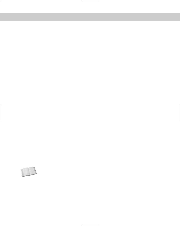
17.Save your drawing. It should look like Figure 4-11.
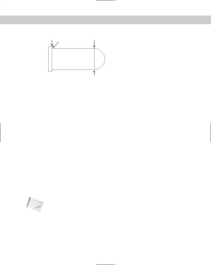
Figure 4-11: The completed drawing of a bolt.
Displaying Coordinates
As you work, you can refer to the coordinate display on the status bar. This display helps you know where your cursor and objects are when you draw and is also helpful when editing, by informing you how far and in what direction you are moving or copying objects.
AutoCAD and AutoCAD LT have three coordinate display modes:
Dynamic absolute coordinates (absolute): Absolute coordinates that change as you move the mouse, as shown in Figure 4-12.
Figure 4-12: Dynamic absolute coordinates.
60 |
Part I AutoCAD and AutoCAD LT Basics |
Static absolute coordinates (off): Absolute coordinates that change only when you specify a point, as shown in Figure 4-13. The coordinate display is dimmed.
Figure 4-13: Static absolute coordinates.
Dynamic polar coordinates (relative): Polar coordinates that change continuously as you move the mouse, as shown in Figure 4-14. They appear after you’ve already specified a point and are ready to specify a new point, as when you’re in the process of drawing a line.
Figure 4-14: Dynamic polar coordinates.
You can change the coordinate display in three ways:
Press the F6 key.
Click the coordinates area on the status bar.
Press Ctrl+D.
For purposes of this chapter, I ignore the Z coordinate that follows the X and Y coordinates (in AutoCAD only). In two-dimensional drawings, the Z coordinate is always zero.
In the following exercise, you practice using the coordinate display options. You can do this exercise with any new or existing drawing open on the screen.
STEP-BY-STEP: Using Coordinate Display Options
1.Look at the coordinate display on the status bar. It should be shown in black. If the coordinates are shown in gray, press F6 on your keyboard.
2.Move the mouse around in a few directions. Notice how the coordinates constantly change with the mouse movement.
3.Press F6. The coordinate display is grayed out. The command line shows <Coords off>.
4.Move the mouse around again. The coordinate display does not change with the movement of the mouse.
5.Start the LINE command and pick any point on the screen.
6.Watch the coordinate display as you pick any point at the Specify next point or [Undo]: prompt.
7.Pick several other points and watch as the coordinate display changes only when you pick a point. This is the static coordinate display.
8.Press F6 again without ending the LINE command.
9.Move the mouse to another point that you would like to pick but watch the coordinate display before you pick the point. This time, the length and angle of the new line segment is shown. These are dynamic polar coordinates.
Chapter 4 Specifying Coordinates |
61 |
10.Pick a few more points, watching the polar coordinates.
11.Press F6 again to return to dynamic absolute coordinates.
12.Press Enter to end the LINE command. Do not save your drawing.
Picking Coordinates on the Screen
The easiest and quickest way to specify coordinates is to pick them directly on the screen with the mouse. Several techniques are available to help you do so accurately.
You can adjust the size of the crosshairs that cross the cursor. By default, they are 5 percent of screen size. To change the crosshair size, choose Tools Options and click the Display tab. In the Crosshair size text box, you can type a new percentage or drag the bar to increase or decrease the percentage. Choose OK.
Snap settings
The SNAP command is often an alternative to tedious entry of coordinates. This command restricts the cursor to an incremental distance that you choose, such as 0.5 units. You can set the snap size to anything you want. For example, if all your measurements are rounded off to the nearest 0.25 units, you can set your snap to 0.25.
The snap technique is not very useful when you need to draw to three or more decimal places of accuracy. And when you’re zoomed out in a large drawing, the snap points may be so close together that you cannot easily find the one you want. But in the right situation, snap is one of the quickest, most accurate drawing techniques available.
AutoCAD and AutoCAD LT provide two types of snap settings — grid snap and polar snap.
Snapping to a grid
When you snap to a grid, an invisible grid becomes active (which you can make visible using the GRID command, discussed in the next section). As soon as you turn on snap, the mouse cursor can move only to the snap grid points.
To set the snap size, choose Tools Drafting Settings or right-click the SNAP button on the status bar and choose Settings. The Drafting Settings dialog box opens, as shown in Figure 4-15. (If necessary, click the Snap and Grid tab.) In the Snap X Spacing text box of the Snap section, type the spacing you want between snap points. Make sure that Grid Snap and Rectangular Snap are checked in the Snap Type & Style section of the dialog box. Click OK.
Cross- |
Note that you can change the angle of the snap spacing. In Chapter 8, I discuss rotating the |
Reference |
angle of the snap and grid. Chapter 8 also discusses Isometric snap, used for isometric |
|
|
|
drawing. |
Usually you want the X spacing (going across) to be the same as the Y spacing (going up and down). You need to specify only the X spacing, and the Y spacing changes automatically to equal the X spacing. X and Y spacing will be different only if you type a different number in the Snap Y spacing box.

62 |
Part I AutoCAD and AutoCAD LT Basics |
Figure 4-15: The Drafting Settings dialog box.
You can also turn snap on in this dialog box by clicking the On check box. However, the most common way to turn snap on, after you’ve set the spacing, is to click SNAP on the status bar (or press the F9 key). Click it again to turn snap off.
Snapping at polar angles
After you set polar tracking settings, discussed earlier in this chapter in the “Polar tracking” section, you can snap to increments along the polar angles you have set. When PolarSnap is on, the polar tooltip only shows distances in increments of the snap setting. When you see the distance you want, just click. PolarSnap makes it easy to draw accurately without having to type coordinates.
To use PolarSnap, follow these steps:
1.Right-click the SNAP button on the status bar and click Settings to open the Drafting Settings dialog box with the Snap and Grid tab displayed, as just explained.
2.Check PolarSnap in the Snap Type & Style section of the dialog box (refer to Figure 4-15).
3.Type a number in the Polar Distance text box.
4.Click OK to close the dialog box.
5.Click SNAP on the status bar.
Note that PolarSnap and Grid Snap are mutually exclusive. If PolarSnap is on, the cursor will not snap to the grid. Used with polar tracking, PolarSnap is a powerful tool. Remember that you can polar track along orthogonal as well as other angles.
Tip |
You can choose either polar snap or grid snap (switch between them) by right-clicking SNAP |
|
on the status bar. A shortcut menu lets you choose the type of snap you want, or turn both off. |
Chapter 4 Specifying Coordinates |
63 |
The grid
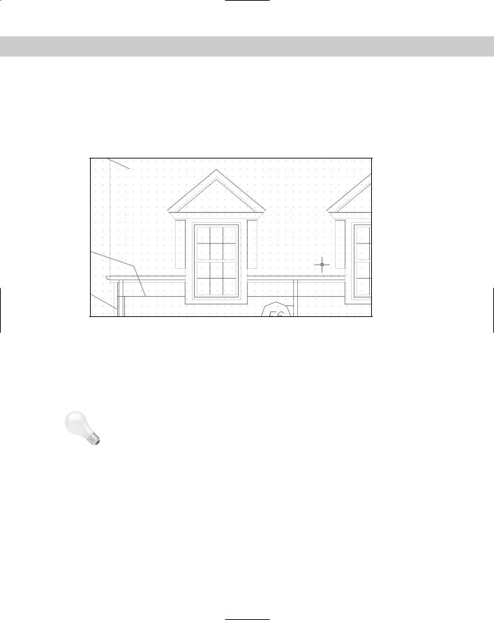
Sometimes you may find it helpful to see a grid of dots to help get your bearings while you draw, as shown in Figure 4-16. If the dot grid is not visible, click GRID on the status bar or press the F7 key. Notice how you can quickly judge the approximate width of a windowpane, knowing that the grid dots are half a foot apart. If you turn on snap, the grid helps you visualize the snap points. However, the grid dots do not have to be set to the same spacing as the snap points.
|
Figure 4-16: A portion of a drawing with the grid turned on and set to 6 inches. |
|
Thanks to Henry Dearborn, AIA, Fairfield, Iowa, for this drawing. |
|
The smaller the grid size and the farther out you zoom, the denser the grid and the longer it |
|
takes to display. At a certain point, you get a message, Grid too dense to display. |
|
Some users find the grid annoying, but when you first start to use AutoCAD or AutoCAD LT, |
|
you may find it helpful. Even accomplished users can take advantage of the grid, especially |
|
when starting a new drawing. |
Tip |
If you’re working with a small snap spacing and the dot grid is too dense, set the dot grid to |
|
two or more times the size of the snap spacing. |
|
To set the grid size, choose Tools Drafting Settings to open the Drafting Settings dialog box |
|
(refer to Figure 4-15). If necessary, click the Snap and Grid tab. In the X Spacing text box of the |
|
Grid section, type the spacing you want between grid points. Click OK. |
|
As with the snap feature, you usually want the X spacing (going across) to be the same as the |
|
Y spacing (going up and down). You only need to specify the X spacing; the Y spacing auto- |
|
matically changes to be the same. X and Y spacing will only be different if you type a different |
|
number in the Y Spacing box. |
|
You can turn on Grid in this dialog box by clicking the On check box, but the most common |
|
way to turn the grid on, after you’ve set the spacing, is to click GRID on the status bar (or |
|
press F7). |
|
In the following exercise, you practice using polar and grid snap points as well as grid dots. |

64 |
Part I AutoCAD and AutoCAD LT Basics |
On the |
The drawing used in the following Step-by-Step exercise on using snap points and grid dots, |
CD-ROM |
ab04-b.dwg, is in the Drawings folder on the CD-ROM. |
STEP-BY-STEP: Using Snap Points and Grid Dots
1.Open ab04-b.dwg from the CD-ROM.
2.Choose File Save As to save the drawing in your AutoCAD Bible folder as ab04-04.dwg.
3.Choose Tools Drafting Settings. The Drafting Settings dialog box opens. Click the Snap and Grid tab if it is not displayed. In the Snap Type & Style section, make sure that you check Grid Snap and Rectangular Snap.
4.In the Snap section, change the Snap X Spacing to 0.5.
5.Click in the Grid section, in the Grid X spacing text box. Change the Grid X spacing to 0.5. Click OK. The Grid Y spacing automatically changes to match the Grid X spacing of 0.5.
6.On the status bar, click SNAP, GRID, and ORTHO. The grid appears. Make sure that the OSNAP and OTRACK buttons on the status bar are off. (AutoCAD LT doesn’t have the OTRACK button.)
7.Choose View Zoom All.
8.Move the mouse around and watch the coordinates on the status bar. (Press F6 if they are in static mode.) They show halves of units because you have set the snap to 0.5.
9.Start the LINE command. At the Specify first point: prompt, click when the coordinates on the status bar show 2.000, 2.000. (AutoCAD users can ignore the third Z coordinate, which is always 0.0000 in 2D drawings.)
10.Move the mouse around and watch the coordinates. If you don’t see polar coordinates (for example 3.0000<0), press F6 until you see them.
11.Move the mouse to the right until the coordinates read 8.5000<0 and click the pick (left) button. You have drawn a horizontal line with a length of 8.5 units.
12.Click the right mouse button and choose Enter to end the LINE command.
13.Move the mouse cursor away from the end of the new line and back to it again, and the absolute coordinates appear. They should be 10.5000,2.0000.
14.Right-click and choose Repeat Line to start the LINE command again. Use the coordinate display to start the line at 1.5000,1.5000. Continue to pick points (rather than type them) and draw the following line segments, as shown in the coordinate display:
.5<0
3.0<90
.5<180
3.0<270
15.End the LINE command.
Chapter 4 Specifying Coordinates |
65 |
16.Start the LINE command and pick points, drawing the following line segments (as shown in the coordinate display) starting from 10.5,1.5. Then end the LINE command:
.5<0
3.0<90
.5<180
3.0<270
17.Starting from 2,4 draw an 8.5-unit line at 0 degrees. End the LINE command.
18.Start the LINE command again. At the first prompt, pick 11,2. Right-click SNAP on the status bar and choose Settings. In the Snap Type & Style section, choose PolarSnap. (This is equivalent to choosing the PolarSnap On feature on the SNAP button shortcut menu.) In the Polar Spacing section, change the Polar Distance to .5. Choose the Polar Tracking tab and (if necessary) set the Increment Angle to 45.0 degrees. Click OK. Click POLAR on the status bar.
19.Move the cursor in a 45-degree direction from 11,2 until you see the tooltip. Move along the polar tracking vector until the tooltip says 3.5000 < 45° and click. End the LINE command.
20.Right-click the SNAP button and choose Grid Snap On. Start the LINE command and, at the Specify first point: prompt, choose 11,4.
21.Right-click the SNAP button and choose PolarSnap On. Move the cursor in a 45-degree direction until the tooltip says 3.5000 < 45° and click. End the LINE command.
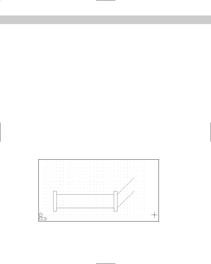
22.Save your drawing. Your drawing should look like Figure 4-17.
As you no doubt experienced, this is a much easier way to draw compared to typing in coordinates. Note that drawing with snap on works better when you’re drawing small objects. However, even when drawing an office building, you spend a great deal of time working on small details that may be easier to draw with snap on.
Figure 4-17: The completed pipe section.
66 |
Part I AutoCAD and AutoCAD LT Basics |
Object snaps
Often you need to draw an object relative to an existing object. For example, you may need to start a line from the endpoint or midpoint of an existing line. Object snaps (OSNAPS for short) enable you to specify a point by snapping to a geometrically defined point on an existing object. This is a very precise and efficient way to draw.
You can start an object snap in one of four ways:
Cross-
Reference
Open the Object Snap toolbar and choose the object snap that you want.
Right-click, choose Snap Overrides from the shortcut menu, and then choose the object snap that you want from the menu.
Access the object snap shortcut menu by holding down the Shift key and right-clicking. Choose the object snap that you want from the shortcut menu.
Type the object snap’s abbreviation on the command line.
On multibutton mice, you can customize one of the buttons to show the Object Snap menu. Displaying the Object Snap menu with the click of a mouse button is very convenient. Customizing the mouse is discussed in Chapter 33.
Table 4-1 lists the object snaps. Use the abbreviation to type the object snap from the keyboard.
Table 4-1: Object Snaps
Object Snap |
Abbreviation |
Uses |
|
|
|
Endpoint |
End |
Lines, arcs, and so on. |
Midpoint |
Mid |
Lines, arcs, and so on. |
Intersection |
Int |
Intersection of lines, circles, arcs. |
Apparent Intersection* |
App |
The intersection that would be created if two objects were |
|
|
extended until they met. |
Extension |
Ext |
Extends lines, arcs, and so on past their endpoints but in the |
|
|
same direction. After choosing this object snap, pause over |
|
|
the endpoint of a line or arc until you see a small plus sign. |
|
|
As you move the mouse cursor along the extension path, a |
|
|
temporary extension path appears so that you can draw to or |
|
|
from points on the extension path. (AutoCAD only.) |
Center |
Cen |
Circles, arcs, ellipses. |
Quadrant |
Qua |
Nearest quadrant (0-, 90-, 180-, or 270-degree point) of a |
|
|
circle, arc, or ellipse. |
Perpendicular |
Per |
Arc, circles, ellipses, lines, multilines, polylines, rays, splines, or |
|
|
construction lines. The Deferred Perpendicular mode lets you |
|
|
draw a line perpendicular from one of these objects. |
Chapter 4 Specifying Coordinates |
67 |
Object Snap |
Abbreviation |
Uses |
|
|
|
Parallel |
Par |
Continues a line, polyline, and so on so that it’s parallel to an |
|
|
existing line or other straight-line segment. After you choose |
|
|
this object snap, pause over the line you want to draw |
|
|
parallel to until you see a small parallel line symbol. As you |
|
|
move the mouse cursor parallel to the object, a temporary |
|
|
parallel path appears to help you create the parallel segment. |
|
|
(AutoCAD only.) |
Tangent |
Tan |
Starts or continues a line from or to a point tangent with an |
|
|
arc, circle, or ellipse (see Figure 4-18). |
Node |
Nod |
Point objects (discussed in Chapter 7). |
Insertion |
Ins |
Insertion point of text (see Chapter 13) or a block (see |
|
|
Chapter 18). |
Nearest |
Nea |
Nearest point on any object. |
None |
Non |
Turns off any object snap modes. |
|
|
|
* Apparent Intersection also applies to 3D objects that appear to intersect due to the angle of view.
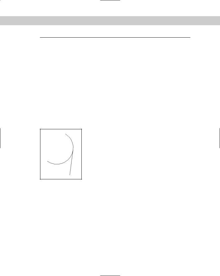
Figure 4-18: A line drawn tangent to an arc.
When drawing a line, we think of it as having a starting point and an ending point. After the line is drawn, however, both of these points are considered endpoints in terms of object snaps. When picking the endpoint of a line for the endpoint object snap, pick a point on the line closer to the endpoint that you want. The same applies to arcs. Although the arc prompts read Start point and End, both are considered endpoints for purposes of object snaps.
AutoSnap is a feature that helps you work with object snaps. When you move the cursor near the geometric point you have specified, such as an endpoint, you are notified in three ways:
Marker: An object snap shape appears. Each object snap has a differently shaped marker.
AutoSnap tooltip: A label displays the name of the object snap.
Magnet: A pull gently moves the cursor toward the geometric point.
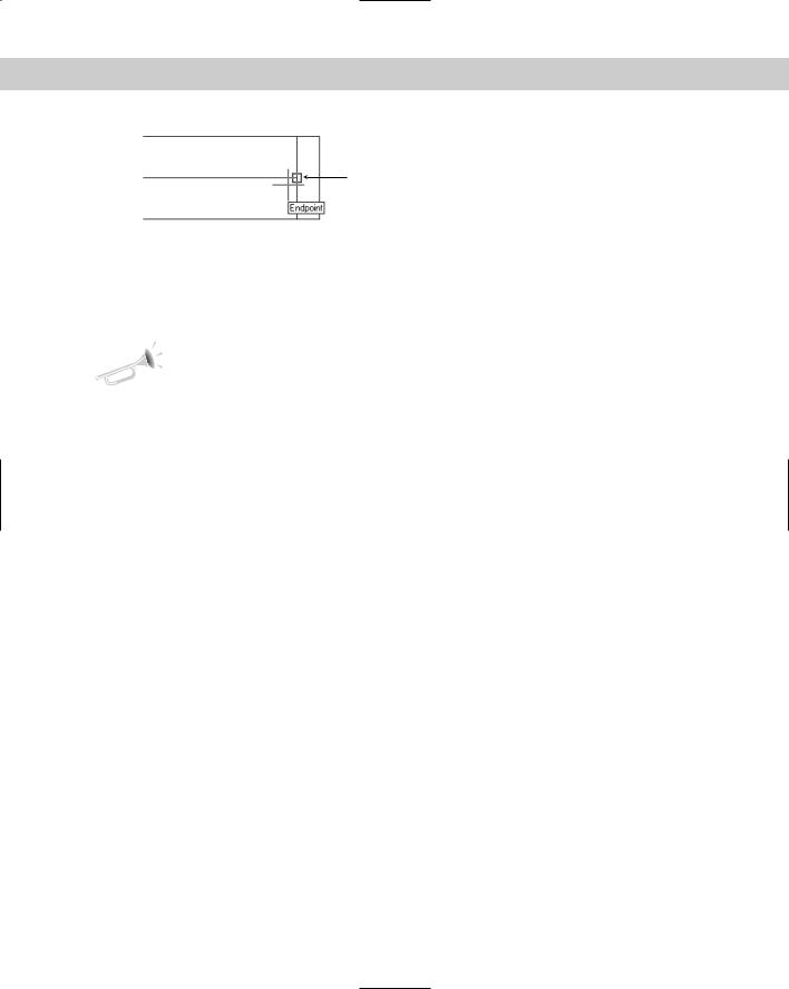
Figure 4-19 shows an endpoint marker and AutoSnap tooltip.
68 |
Part I AutoCAD and AutoCAD LT Basics |
Marker
 Tooltip
Figure 4-19: AutoSnap shows you the endpoint of the line.
You can customize the AutoSnap feature to suit your needs or make it go away completely if you want. Choose Tools Options and click the Drafting tab. Here you can individually turn on and off the marker, AutoSnap tooltip, and the magnet. You can also change the marker size and color.
New |
The Deferred Perpendicular mode has been enhanced to give you a more visual cue to pos- |
Feature |
sible perpendicular lines. This mode enables you to draw perpendicular lines from an object. |
|
|
|
Start the line command and choose the Perpendicular object snap. Click the object that you |
|
want to draw perpendicular from and then move the cursor away from that object. You see |
|
the Deferred Perpendicular tooltip and a temporary perpendicular line that follows your cur- |
|
sor along the original object. Pick another object or use another object snap to complete the |
|
perpendicular line. |
In the following exercise, you practice using object snaps.
STEP-BY-STEP: Using Object Snaps
1.Start a new drawing using the acad.dwt or aclt.dwt template.
2.Save the drawing in your AutoCAD Bible folder as ab04-05.dwg.
3.Click ORTHO on the status bar to turn on ortho mode. If the OSNAP button is on, click OSNAP on the status bar to turn off running object snaps (covered in the next section).
4.Start the LINE command. Follow the prompts:
Specify first point: 2,7 . Move the cursor downward.
Specify next point or [Undo]: 4 . Move the cursor to the right. Specify next point or [Undo]: 4 . Move the cursor up.
Specify next point or [Close/Undo]: 4
Specify next point or [Close/Undo]: Press Enter to end the command.
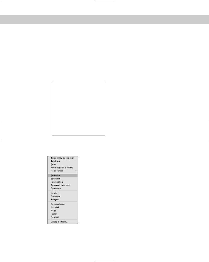
Your drawing should look like Figure 4-20. The circled numbers are reference points for this exercise.
5.Choose Arc from the Draw toolbar. Follow these prompts:
Specify start point of arc or [Center]: Press Shift and right-click. From the shortcut menu, choose Endpoint, as shown in Figure 4-21.
_endpt of Move the cursor to 1 in Figure 4-20. When you see the endpoint marker and AutoSnap tooltip, click.
Chapter 4 Specifying Coordinates |
69 |
Specify second point of arc or [Center/End]: Right-click and choose Center.
Specify center point of arc: Right-click. Choose Snap Overrides Midpoint from the shortcut menu.
_mid of Move the cursor to 2 and pick.
Specify end point of arc or [Angle/chord Length]: end . Move the cursor to 3 and pick.
4 |
3 |
2
1
Figure 4-20: These three lines are the start of a mounting bracket.
Figure 4-21: Choosing the Endpoint object snap from the shortcut menu.
70 |
Part I AutoCAD and AutoCAD LT Basics |
6. Choose Circle from the Draw menu. Follow the prompts:
|
Specify center point for circle or [3P/2P/Ttr (tan tan radius)]: |
|
Choose Snap to Center from the Object Snap shortcut menu. |
|
_cen of Move the cursor over the arc until you see the Center marker |
|
and tooltip, and then click. |
|
Specify radius of circle or [Diameter]: .75 |
|
7. Start the LINE command and use any method you want to draw a line from the end- |
|
point at 3 to the endpoint at 4. End the LINE command. |
Note |
When you press Shift and right-click to get the object snap menu, the mouse pointer must be |
|
in the drawing area. If it is on a toolbar, you get the Toolbars list. If that happens, press the |
|
Esc key, or hold down the Shift button and right-click again in the drawing area. |
|
8. Save your drawing. It should look like Figure 4-22. |
|
Figure 4-22: The start of a drawing |
|
of a mounting bracket (including a |
|
construction line that would later be |
|
erased). It was created by using the |
|
endpoint, midpoint, and center object |
|
snaps. |
Running object snaps and OSNAP mode
The endpoint object snap is probably the most commonly used of all the object snaps. You might have a drawing project in which you need to use the endpoint object snap often. You can set a running object snap, which keeps one or more object snaps on until you turn them off.
Tip Many users like to work with three or four running object snaps on at once, such as endpoint, midpoint, center, and intersection. If you can’t find the object snap you want because you have several object snaps near each other, press the Tab key to cycle through the object snaps, one by one, until you find the one that you want.
To set running object snaps, choose Tools Drafting Settings (or right-click the OSNAP button on the status bar and choose Settings) to open the Drafting Settings dialog box, as shown in Figure 4-23. (If necessary, click the Object Snap tab.) Choose the object snaps that you want and click OK. To clear a checked object snap, click it. Click Clear All to clear all running snaps.

Chapter 4 Specifying Coordinates |
71 |
Figure 4-23: Use the Object Snap tab of the Drafting Settings dialog box to set running object snaps.
You use the OSNAP button on the status bar to turn on your running object snaps. If you want to turn them off temporarily, just click the OSNAP button or press F3. This capability to toggle running object snaps on and off makes it easy to work with running object snaps on almost all the time because you can turn them off at the click of a button.
In the following exercise, you practice using running object snaps with OSNAP mode.
STEP-BY-STEP: Using Running Object Snaps with OSNAP Mode
1.Start a new drawing using the acad.dwt or aclt.dwt template. Save the file in your
AutoCAD Bible folder as ab04-06.dwg.
2.Choose Tools Drafting Settings and click the Object Snap tab. Choose Endpoint. Uncheck all other object snaps and click OK.
3.Start the LINE command and start the line at 2,2.
4.Turn on ortho mode by clicking ORTHO on the status bar. If OSNAP is not on, click it on the status bar.
5.Move the mouse in the 0-degree direction and type 6 .
6.Move the mouse up in the 90-degree direction, type 3 , and end the LINE command.
7.Start the ARC command. At the Specify start point of arc or [Center]: prompt, pick the endpoint at 1, shown in Figure 4-24. (Look for the marker and AutoSnap tooltip.)
8.At the Specify second point of arc or [Center/End]: prompt, right-click and choose End. Pick the endpoint at 2, shown in Figure 4-24.
72 |
Part I AutoCAD and AutoCAD LT Basics |
4 |
3 |
2 |
1
Figure 4-24: Drawing a steam boiler with an endpoint running object snap.
9.At the Specify center point of arc or [Angle/Direction/Radius]: prompt, right-click and choose Angle, and then type 180 .
10.Start the LINE command and at the Specify first point: prompt, pick the endpoint at 2 in Figure 4-24.
11.Move the mouse to the left in the 180-degree direction, type 6 , and end the LINE command.
12.Right-click the SNAP button on the status bar and choose Settings. Click Grid Snap in the Snap Type & Style section. Set the Snap X spacing to 0.25. Check the Snap On check box. Click OK.
13.Start the LINE command. At the Specify first point: prompt, place the cursor 0.25 units above 3 in Figure 4-24 (at 2,5.25). You may need to turn off the running OSNAP temporarily. Pick point 2,5.25.
14.At the Specify next point or [Undo]: prompt, pick point 2,1.75. (If necessary, press F6 to get absolute coordinates.)
15.Press F6 twice to get polar coordinates. Follow the prompts:
Specify next point or [Undo]: Pick .5<180. Specify next point or [Close/Undo]: Pick 3.5<90.
Specify next point or [Close/Undo]: Pick the endpoint at 4 in
Figure 4-24. (If you turned off OSNAP in Step 13, turn it on again.)
Specify next point or [Close/Undo]:
16.Save your drawing.
Note Even if you have running object snaps, if you specify an object snap during a command, it overrides the running object snap. For example, having a running endpoint object snap does not mean you can’t use a midpoint object snap for any specific drawing command.
By default, if you type absolute or relative coordinates, they take precedence over any running object snaps. This lets you leave running object snaps on but override them with keyboard entry of typed coordinates whenever you want. In general, the default gives you the