

- •Foreword
- •Preface
- •Is This Book for You?
- •How This Book Is Organized
- •How to Use This Book
- •Doing the Exercises
- •Conventions Used in This Book
- •What the Icons Mean
- •About the CD-ROM
- •Other Information
- •Contacting the Author
- •Acknowledgments
- •Contents at a Glance
- •Contents
- •Getting Acquainted with AutoCAD and AutoCAD LT
- •Starting AutoCAD and AutoCAD LT
- •Creating a New Drawing
- •Using the AutoCAD and AutoCAD LT Interface
- •Creating Your First Drawing
- •Saving a Drawing
- •Summary
- •Creating a New Drawing from a Template
- •Working with Templates
- •Opening a Drawing with Default Settings
- •Opening an Existing Drawing
- •Using an Existing Drawing as a Prototype
- •Saving a Drawing Under a New Name
- •Summary
- •The Command Line
- •Command Techniques
- •Of Mice and Pucks
- •Getting Help
- •Summary
- •Typing Coordinates
- •Displaying Coordinates
- •Picking Coordinates on the Screen
- •Locating Points
- •Summary
- •Unit Types
- •Drawing Limits
- •Understanding Scales
- •Inserting a Title Block
- •Common Setup Options
- •The MVSETUP Command
- •Summary
- •Using the LINE Command
- •Drawing Rectangles
- •Drawing Polygons
- •Creating Construction Lines
- •Creating Rays
- •Summary
- •Drawing Circles
- •Drawing Arcs
- •Creating Ellipses and Elliptical Arcs
- •Making Donuts
- •Placing Points
- •Summary
- •Panning
- •The ZOOM Command
- •Aerial View
- •Named Views
- •Tiled Viewports
- •Snap Rotation
- •User Coordinate Systems
- •Isometric Drawing
- •Summary
- •Editing a Drawing
- •Selecting Objects
- •Summary
- •Copying and Moving Objects
- •Using Construction Commands
- •Creating a Revision Cloud
- •Hiding Objects with a Wipeout
- •Double-Clicking to Edit Objects
- •Grips
- •Editing with the Properties Palette
- •Selection Filters
- •Groups
- •Summary
- •Working with Layers
- •Changing Object Color, Linetype, and Lineweight
- •Working with Linetype Scales
- •Importing Layers and Linetypes from Other Drawings
- •Matching Properties
- •Summary
- •Drawing-Level Information
- •Object-Level Information
- •Measurement Commands
- •AutoCAD’s Calculator
- •Summary
- •Creating Single-Line Text
- •Understanding Text Styles
- •Creating Multiline Text
- •Creating Tables
- •Inserting Fields
- •Managing Text
- •Finding Text in Your Drawing
- •Checking Your Spelling
- •Summary
- •Working with Dimensions
- •Drawing Linear Dimensions
- •Drawing Aligned Dimensions
- •Creating Baseline and Continued Dimensions
- •Dimensioning Arcs and Circles
- •Dimensioning Angles
- •Creating Ordinate Dimensions
- •Drawing Leaders
- •Using Quick Dimension
- •Editing Dimensions
- •Summary
- •Understanding Dimension Styles
- •Defining a New Dimension Style
- •Changing Dimension Styles
- •Creating Geometric Tolerances
- •Summary
- •Creating and Editing Polylines
- •Drawing and Editing Splines
- •Creating Regions
- •Creating Boundaries
- •Creating Hatches
- •Creating and Editing Multilines
- •Creating Dlines
- •Using the SKETCH Command
- •Digitizing Drawings with the TABLET Command
- •Summary
- •Preparing a Drawing for Plotting or Printing
- •Creating a Layout in Paper Space
- •Working with Plot Styles
- •Plotting a Drawing
- •Summary
- •Combining Objects into Blocks
- •Inserting Blocks and Files into Drawings
- •Managing Blocks
- •Using Windows Features
- •Working with Attributes
- •Summary
- •Understanding External References
- •Editing an Xref within Your Drawing
- •Controlling Xref Display
- •Managing Xrefs
- •Summary
- •Preparing for Database Connectivity
- •Connecting to Your Database
- •Linking Data to Drawing Objects
- •Creating Labels
- •Querying with the Query Editor
- •Working with Query Files
- •Summary
- •Working with 3D Coordinates
- •Using Elevation and Thickness
- •Working with the User Coordinate System
- •Summary
- •Working with the Standard Viewpoints
- •Using DDVPOINT
- •Working with the Tripod and Compass
- •Getting a Quick Plan View
- •Shading Your Drawing
- •Using 3D Orbit
- •Using Tiled Viewports
- •Defining a Perspective View
- •Laying Out 3D Drawings
- •Summary
- •Drawing Surfaces with 3DFACE
- •Drawing Surfaces with PFACE
- •Creating Polygon Meshes with 3DMESH
- •Drawing Standard 3D Shapes
- •Drawing a Revolved Surface
- •Drawing an Extruded Surface
- •Drawing Ruled Surfaces
- •Drawing Edge Surfaces
- •Summary
- •Drawing Standard Shapes
- •Creating Extruded Solids
- •Drawing Revolved Solids
- •Creating Complex Solids
- •Sectioning and Slicing Solids
- •Using Editing Commands in 3D
- •Editing Solids
- •Listing Solid Properties
- •Summary
- •Understanding Rendering
- •Creating Lights
- •Creating Scenes
- •Working with Materials
- •Using Backgrounds
- •Doing the Final Render
- •Summary
- •Accessing Drawing Components with the DesignCenter
- •Accessing Drawing Content with Tool Palettes
- •Setting Standards for Drawings
- •Organizing Your Drawings
- •Working with Sheet Sets
- •Maintaining Security
- •Keeping Track of Referenced Files
- •Handling Errors and Crashes
- •Managing Drawings from Prior Releases
- •Summary
- •Importing and Exporting Other File Formats
- •Working with Raster Images
- •Pasting, Linking, and Embedding Objects
- •Summary
- •Sending Drawings
- •Opening Drawings from the Web
- •Creating Object Hyperlinks
- •Publishing Drawings
- •Summary
- •Working with Customizable Files
- •Creating Keyboard Shortcuts for Commands
- •Customizing Toolbars
- •Customizing Tool Palettes
- •Summary
- •Creating Macros with Script Files
- •Creating Slide Shows
- •Creating Slide Libraries
- •Summary
- •Creating Linetypes
- •Creating Hatch Patterns
- •Summary
- •Creating Shapes
- •Creating Fonts
- •Summary
- •Working with Menu Files
- •Customizing a Menu
- •Summary
- •Introducing Visual LISP
- •Getting Help in Visual LISP
- •Working with AutoLISP Expressions
- •Using AutoLISP on the Command Line
- •Creating AutoLISP Files
- •Summary
- •Creating Variables
- •Working with AutoCAD Commands
- •Working with Lists
- •Setting Conditions
- •Managing Drawing Objects
- •Getting Input from the User
- •Putting on the Finishing Touches
- •Summary
- •Understanding Local and Global Variables
- •Working with Visual LISP ActiveX Functions
- •Debugging Code
- •Summary
- •Starting to Work with VBA
- •Writing VBA Code
- •Getting User Input
- •Creating Dialog Boxes
- •Modifying Objects
- •Debugging and Trapping Errors
- •Moving to Advanced Programming
- •A Final Word
- •Installing AutoCAD and AutoCAD LT
- •Configuring AutoCAD
- •Starting AutoCAD Your Way
- •Configuring a Plotter
- •System Requirements
- •Using the CD with Microsoft Windows
- •What’s on the CD
- •Troubleshooting
- •Index
Chapter 21 Specifying 3D Coordinates 615
21.Start the ARC command. The start point should be at the left quadrant of the left circle you just drew. The second point is the intersection of the vertical centerline and the top horizontal centerline. (There is an Endpoint object snap there.) The endpoint is the right quadrant of the right circle.
22.Choose Tools New UCS World. Choose View 3D Views SE Isometric. Then type hide to see the final result.
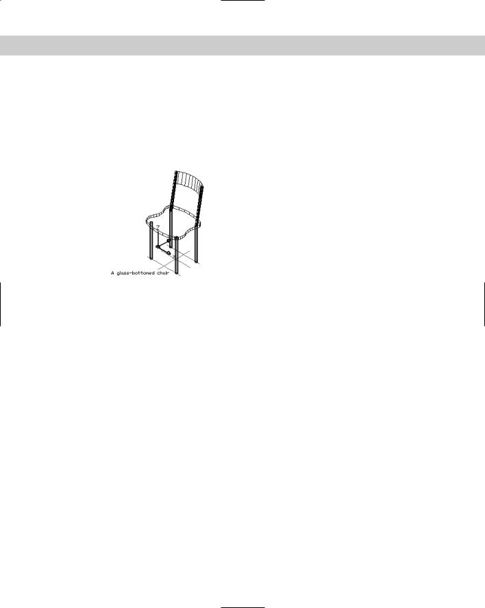
23.Save your drawing. The chair should look like Figure 21-19.
Figure 21-19: The completed glass-bottomed chair.
Summary
This chapter introduced you to 3D drawing. You read about:
Understanding all the types of 3D coordinates and how to use them
Using editing commands in 3D
Using point filters, object snaps, and grips in 3D drawings
Utilizing elevation and thickness
Understanding the HIDE command and the system variables that affect the hidden display
Working with User Coordinate Systems in 3D
In the next chapter, I explain all the ways to view 3D drawings.
|
|
|


Viewing 3D
Drawings
As soon as you start to work in three dimensions, you need to be able to see the drawing from different angles. By combining vari-
ous User Coordinate Systems (UCSs) and different viewpoints, you can draw any object in 3D.
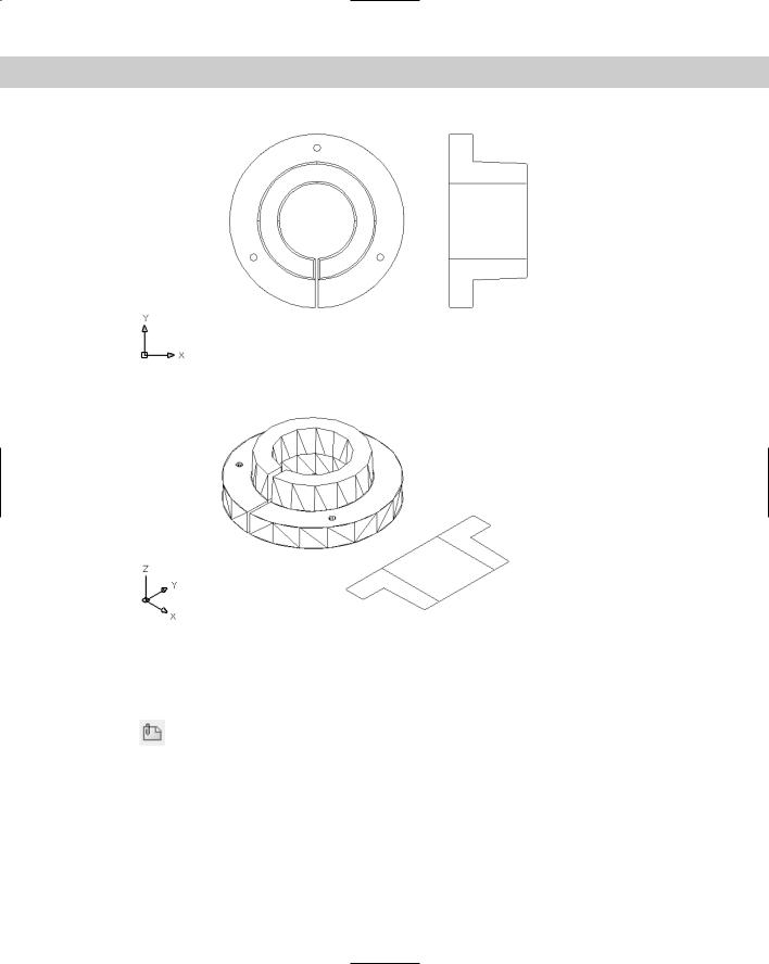
Your basic point of reference is plan view in the World Coordinate System (WCS). This is the way you draw in 2D, so it’s familiar. Plan view is the view from the top. For a building, the top is obvious. However, for a bushing, which view is the top? Figure 22-1 shows a 2D drawing of a bushing. Figure 22-2 shows the 3D version. The left view of Figure 22-1 is the plan view looking down from the top. (Although your drawing calls this the plan view, engineering practice might call this the front view.)
When working in 3D, you can use many of the familiar 2D techniques for viewing your drawing:
Use ZOOM Previous to display the previous viewpoint.
Save views so that you can easily return to them.
Use real-time zoom and pan as well as all the other zoom options.
Create tiled viewports to display more than one view at a time.
22C H A P T E R
In This Chapter
Using the standard viewpoints
Using the DDVPOINT and VPOINT commands
Getting a plan view with the PLAN command
Shading your drawing
Using 3D orbit
Creating a perspective view
Laying out a 3D drawing
618 Part IV Drawing in Three Dimensions
Figure 22-1: The left image is the plan view, looking down from the top.
Thanks to Robert Mack, the Dexter Company, Fairfield, Iowa, for this drawing.
Figure 22-2: A 3D view of the bushing after using the HIDE command.
Working with the Standard Viewpoints
The View toolbar offers ten standard viewpoints. (Right-click any toolbar and choose View to display the View toolbar.) These viewpoints are useful — and easy to use —
because they’re the most commonly used viewpoints. You can do a lot of your work just using these viewpoints. The standard viewpoints show viewpoints relative only to the WCS, not the current UCS. Therefore, they’re most useful when you’re using the WCS.
To use a preset viewpoint, you can choose it from the View toolbar. You can also choose View 3D Views and choose the viewpoint you want from the submenu. Each of the preset viewpoints automatically does a Zoom Extents.

Chapter 22 Viewing 3D Drawings 619
Using the VPOINT command
The VPOINT command was the original, command-line method of setting viewpoints. Now it’s generally used for scripts and AutoLISP routines when you need a way to set a viewpoint from the command line. (AutoCAD LT does not support AutoLISP routines.)
The VPOINT command defines a viewpoint using X, Y, and Z vectors. The vectors for the standard viewpoints are based on a maximum of 1 unit. Imagine a model of the three axes floating out in space. You’re Superman and can fly around the model from any angle. When you’re over the Z axis, you can define the Z vector from 0,0,0 to your position as 1. The other vectors are 0 (zero) because you’re right over them, so that 0,0,1 defines the top, or plan, view. The next section shows the vector equivalents for the standard viewpoints, to give you a feel for the vector system.
The VPOINT command also has a Rotate option that is the command-line equivalent of the DDVPOINT command’s Viewpoint Presets dialog box. Using this option, you define a viewpoint by the angle from the X axis in the XY plane and then the angle from the XY plane.
|
Looking at a drawing from the standard viewpoints |
|
Showing the viewpoints is easier than describing them. Here I show a simple 3D house from |
|
all ten standard viewpoints. |
Note |
A system variable, UCSORTHO, automatically changes the UCS to match the viewpoint when |
|
you switch to one of the orthographic (top, bottom, left, right, front, and back) viewpoints. In |
|
order to distinguish between the viewpoints and UCSs, I’ve turned UCSORTHO off for the fol- |
|
lowing section. |
|
Top view |
|
The top view is the plan view. You’re looking at the model from a bird’s-eye perspective, |
|
suspended over the model. The VPOINT equivalent is 0,0,1. Figure 22-3 shows a house |
|
from the top. |
Figure 22-3: The top viewpoint of a 3D house.
620 Part IV Drawing in Three Dimensions
You can also get this view by typing PLAN on the command line. Note that the PLAN command does not change the UCS even though you choose to see the plan view of a different UCS. This actually makes it very flexible — you can see what your drawing looks like from a different UCS without actually changing the UCS. The PLAN command is explained later in this chapter.
Bottom view
The bottom view is the plan view for groundhogs. It’s not very useful for buildings, but it may be useful for 3D mechanical drawings. The VPOINT equivalent is 0,0,–1. Fig-
ure 22-4 shows the house from the bottom. Notice the direction of the UCS icon. Also, the square is missing on the icon, indicating you’re viewing from the negative Z direction, or from “underneath.”
Figure 22-4: The bottom viewpoint of the 3D house.
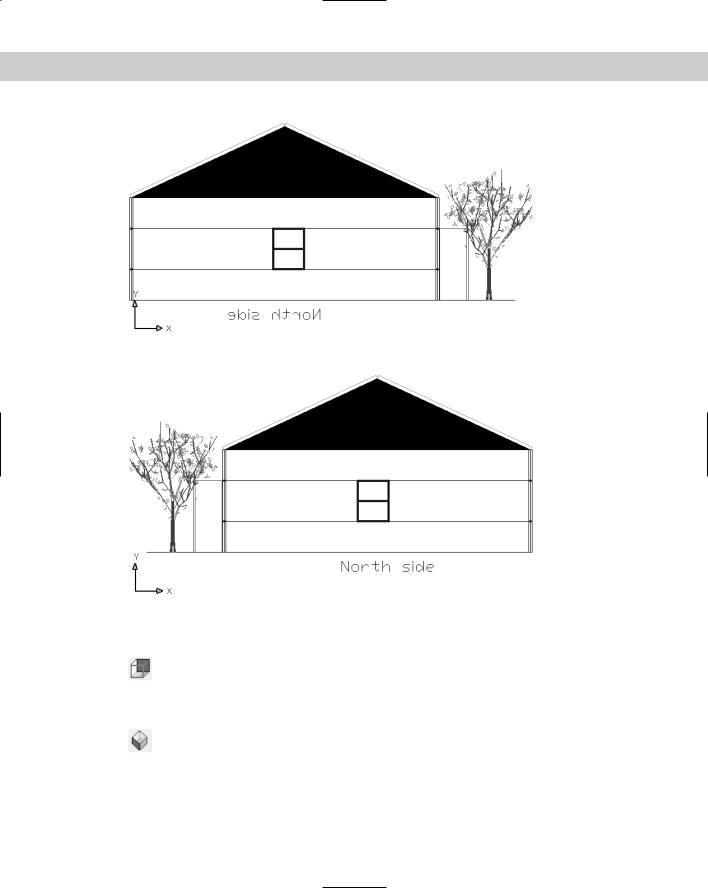
Left view
The left view shows you your model from the side — the left side, of course. In architecture it would be one of the elevation views. The VPOINT equivalent is –1,0,0. Figure 22-5
shows the house from the left view. Notice the backward text. The text was drawn from the right view.
Right view
The right view shows you your model from the right side. Like left view, right view is an elevation view. The VPOINT equivalent is 1,0,0. Figure 22-6 shows the house from the
right view. Notice that the text now appears correctly because it was drawn from this view.
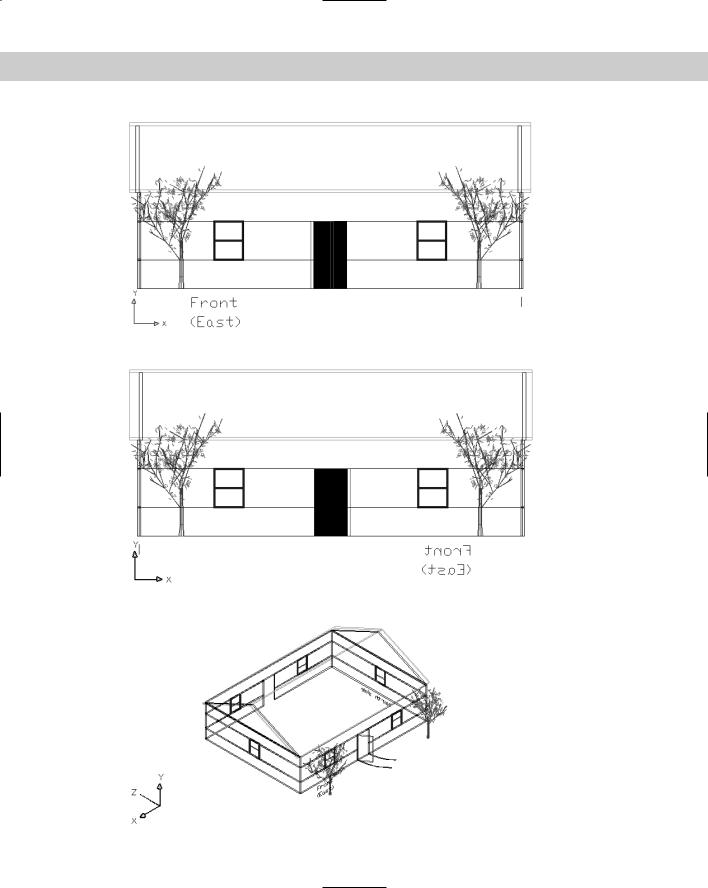
Front view
The front view, another elevation view, shows your model from the front. The VPOINT equivalent is 0,–1,0. Figure 22-7 shows the house from the front. The text, stating that
the front faces the east, doesn’t represent any rule in AutoCAD or AutoCAD LT. It simply helps you see the differences in the sides of the house.
Chapter 22 Viewing 3D Drawings 621
Figure 22-5: The left view of the 3D house.
Figure 22-6: The right view of the 3D house.
Back view
The back view, another elevation view, shows your model from the back, as shown in Figure 22-8. Here you see the text of the front of the house, shown backward. The
VPOINT equivalent is 0,1,0.
SW isometric view
The SW (southwest) isometric view shows you your model from a diagonal viewpoint in all three dimensions (see Figure 22-9). Notice how one corner of the house is closest to you (the corner between the left and front views), and you’re also looking at the house from a
view halfway between a side view and the top view. The isometric views are excellent for viewing all the 3D objects in a drawing. As you can see, many more objects are visible than with the top view or any of the side views. The VPOINT equivalent is –1,–1,1.
622 Part IV Drawing in Three Dimensions
Figure 22-7: The front view of the 3D house.
Figure 22-8: The back view of the 3D house.
Figure 22-9: The SW isometric view of the 3D house.

Chapter 22 Viewing 3D Drawings 623
Don’t get confused with the house’s direction — the is front facing east. From your drawing’s point of view, east is 0 degrees when looking from the top view, and 0 degrees faces to the right.
SE isometric view
The SE (southeast) isometric view also shows your model from a diagonal viewpoint in all three dimensions. Here you’re looking at the house at the corner between the right
and front views, as well as halfway between a side view and the top view. You see the same objects as you do in SW isometric view. However, in a drawing not as symmetrical as the house, one view may bring certain objects to the front so that you can select them. The VPOINT equivalent is 1,–1,1. Figure 22-10 shows the house from the SE isometric view.
Figure 22-10: The SE isometric view of the 3D house.
NE isometric view
The NE isometric view shows your model from the corner between the right and the back views, as well as halfway between a side view and the top view. The VPOINT equiv-
alent is 1,1,1. Figure 22-11 shows the house from the NE isometric view.
Figure 22-11: The NE isometric view of the 3D house.