

- •Foreword
- •Preface
- •Is This Book for You?
- •How This Book Is Organized
- •How to Use This Book
- •Doing the Exercises
- •Conventions Used in This Book
- •What the Icons Mean
- •About the CD-ROM
- •Other Information
- •Contacting the Author
- •Acknowledgments
- •Contents at a Glance
- •Contents
- •Getting Acquainted with AutoCAD and AutoCAD LT
- •Starting AutoCAD and AutoCAD LT
- •Creating a New Drawing
- •Using the AutoCAD and AutoCAD LT Interface
- •Creating Your First Drawing
- •Saving a Drawing
- •Summary
- •Creating a New Drawing from a Template
- •Working with Templates
- •Opening a Drawing with Default Settings
- •Opening an Existing Drawing
- •Using an Existing Drawing as a Prototype
- •Saving a Drawing Under a New Name
- •Summary
- •The Command Line
- •Command Techniques
- •Of Mice and Pucks
- •Getting Help
- •Summary
- •Typing Coordinates
- •Displaying Coordinates
- •Picking Coordinates on the Screen
- •Locating Points
- •Summary
- •Unit Types
- •Drawing Limits
- •Understanding Scales
- •Inserting a Title Block
- •Common Setup Options
- •The MVSETUP Command
- •Summary
- •Using the LINE Command
- •Drawing Rectangles
- •Drawing Polygons
- •Creating Construction Lines
- •Creating Rays
- •Summary
- •Drawing Circles
- •Drawing Arcs
- •Creating Ellipses and Elliptical Arcs
- •Making Donuts
- •Placing Points
- •Summary
- •Panning
- •The ZOOM Command
- •Aerial View
- •Named Views
- •Tiled Viewports
- •Snap Rotation
- •User Coordinate Systems
- •Isometric Drawing
- •Summary
- •Editing a Drawing
- •Selecting Objects
- •Summary
- •Copying and Moving Objects
- •Using Construction Commands
- •Creating a Revision Cloud
- •Hiding Objects with a Wipeout
- •Double-Clicking to Edit Objects
- •Grips
- •Editing with the Properties Palette
- •Selection Filters
- •Groups
- •Summary
- •Working with Layers
- •Changing Object Color, Linetype, and Lineweight
- •Working with Linetype Scales
- •Importing Layers and Linetypes from Other Drawings
- •Matching Properties
- •Summary
- •Drawing-Level Information
- •Object-Level Information
- •Measurement Commands
- •AutoCAD’s Calculator
- •Summary
- •Creating Single-Line Text
- •Understanding Text Styles
- •Creating Multiline Text
- •Creating Tables
- •Inserting Fields
- •Managing Text
- •Finding Text in Your Drawing
- •Checking Your Spelling
- •Summary
- •Working with Dimensions
- •Drawing Linear Dimensions
- •Drawing Aligned Dimensions
- •Creating Baseline and Continued Dimensions
- •Dimensioning Arcs and Circles
- •Dimensioning Angles
- •Creating Ordinate Dimensions
- •Drawing Leaders
- •Using Quick Dimension
- •Editing Dimensions
- •Summary
- •Understanding Dimension Styles
- •Defining a New Dimension Style
- •Changing Dimension Styles
- •Creating Geometric Tolerances
- •Summary
- •Creating and Editing Polylines
- •Drawing and Editing Splines
- •Creating Regions
- •Creating Boundaries
- •Creating Hatches
- •Creating and Editing Multilines
- •Creating Dlines
- •Using the SKETCH Command
- •Digitizing Drawings with the TABLET Command
- •Summary
- •Preparing a Drawing for Plotting or Printing
- •Creating a Layout in Paper Space
- •Working with Plot Styles
- •Plotting a Drawing
- •Summary
- •Combining Objects into Blocks
- •Inserting Blocks and Files into Drawings
- •Managing Blocks
- •Using Windows Features
- •Working with Attributes
- •Summary
- •Understanding External References
- •Editing an Xref within Your Drawing
- •Controlling Xref Display
- •Managing Xrefs
- •Summary
- •Preparing for Database Connectivity
- •Connecting to Your Database
- •Linking Data to Drawing Objects
- •Creating Labels
- •Querying with the Query Editor
- •Working with Query Files
- •Summary
- •Working with 3D Coordinates
- •Using Elevation and Thickness
- •Working with the User Coordinate System
- •Summary
- •Working with the Standard Viewpoints
- •Using DDVPOINT
- •Working with the Tripod and Compass
- •Getting a Quick Plan View
- •Shading Your Drawing
- •Using 3D Orbit
- •Using Tiled Viewports
- •Defining a Perspective View
- •Laying Out 3D Drawings
- •Summary
- •Drawing Surfaces with 3DFACE
- •Drawing Surfaces with PFACE
- •Creating Polygon Meshes with 3DMESH
- •Drawing Standard 3D Shapes
- •Drawing a Revolved Surface
- •Drawing an Extruded Surface
- •Drawing Ruled Surfaces
- •Drawing Edge Surfaces
- •Summary
- •Drawing Standard Shapes
- •Creating Extruded Solids
- •Drawing Revolved Solids
- •Creating Complex Solids
- •Sectioning and Slicing Solids
- •Using Editing Commands in 3D
- •Editing Solids
- •Listing Solid Properties
- •Summary
- •Understanding Rendering
- •Creating Lights
- •Creating Scenes
- •Working with Materials
- •Using Backgrounds
- •Doing the Final Render
- •Summary
- •Accessing Drawing Components with the DesignCenter
- •Accessing Drawing Content with Tool Palettes
- •Setting Standards for Drawings
- •Organizing Your Drawings
- •Working with Sheet Sets
- •Maintaining Security
- •Keeping Track of Referenced Files
- •Handling Errors and Crashes
- •Managing Drawings from Prior Releases
- •Summary
- •Importing and Exporting Other File Formats
- •Working with Raster Images
- •Pasting, Linking, and Embedding Objects
- •Summary
- •Sending Drawings
- •Opening Drawings from the Web
- •Creating Object Hyperlinks
- •Publishing Drawings
- •Summary
- •Working with Customizable Files
- •Creating Keyboard Shortcuts for Commands
- •Customizing Toolbars
- •Customizing Tool Palettes
- •Summary
- •Creating Macros with Script Files
- •Creating Slide Shows
- •Creating Slide Libraries
- •Summary
- •Creating Linetypes
- •Creating Hatch Patterns
- •Summary
- •Creating Shapes
- •Creating Fonts
- •Summary
- •Working with Menu Files
- •Customizing a Menu
- •Summary
- •Introducing Visual LISP
- •Getting Help in Visual LISP
- •Working with AutoLISP Expressions
- •Using AutoLISP on the Command Line
- •Creating AutoLISP Files
- •Summary
- •Creating Variables
- •Working with AutoCAD Commands
- •Working with Lists
- •Setting Conditions
- •Managing Drawing Objects
- •Getting Input from the User
- •Putting on the Finishing Touches
- •Summary
- •Understanding Local and Global Variables
- •Working with Visual LISP ActiveX Functions
- •Debugging Code
- •Summary
- •Starting to Work with VBA
- •Writing VBA Code
- •Getting User Input
- •Creating Dialog Boxes
- •Modifying Objects
- •Debugging and Trapping Errors
- •Moving to Advanced Programming
- •A Final Word
- •Installing AutoCAD and AutoCAD LT
- •Configuring AutoCAD
- •Starting AutoCAD Your Way
- •Configuring a Plotter
- •System Requirements
- •Using the CD with Microsoft Windows
- •What’s on the CD
- •Troubleshooting
- •Index
794 Part V Organizing and Managing Drawings
Specify first extension line origin or <select object>: Pick the upper left corner of the porch.
Specify second extension line origin: Pick the upper right corner of the porch. Specify dimension line location or [Mtext/Text/Angle/Horizontal/Vertical/Rotated]: Pick any location for the dimension line above the steps.
14.Choose Zoom Window from the Zoom flyout on the Standard toolbar and zoom into the central area of the drawing so that you can still see the double doors at the bottom and the steps at the top.
15.Switch back to the 2d arch tab and click the Post icon. At the Specify insertion point: prompt, pick the intersection at 4 in Figure 26-8. Click the Post-Structural icon. At the prompt, pick the upper-right corner of the post block, as shown in Figure 26-9.
16.Click the Post icon. At the prompt, pick 5 in Figure 26-8. Use the same technique to place the Post-Structural icon at the upper-right corner of the post block. (The posts would then need to be spaced and mirrored to the other side of the porch, but these tasks are not necessary for this exercise.)
17.Right-click the tool palette’s title bar. If Allow Docking is checked, click Allow Docking to uncheck this item. If Auto-Hide is not checked, click Auto-Hide to enable this feature. Move the mouse off the tool palette. It collapses to its title bar. Move the tool palette to the right side of your screen.
18.If you’re working on someone else’s computer, you should delete the tool palette. Move the cursor over the palette to display it. Right-click any blank area and choose Delete Tool Palette. Click Yes to confirm the deletion.
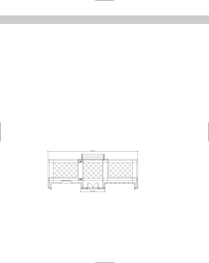
19.Save your drawing. It should look like Figure 26-9.
Figure 26-9: The drawing now has hatches and blocks inserted from the tool palette. It also has a new dimension.
Setting Standards for Drawings
One person rarely has complete control over a drawing. You may xref in other drawings, or others may xref in your drawings. Several people may work on one drawing. You may send a drawing to a client who may work on it as well. More and more, working on a drawing is becoming a collaborative effort — and it can get out of control.

Chapter 26 Keeping Control of Your Drawings |
795 |
One way to get in control is to set standards for drawings — and issue those standards so that everyone involved has access to them. If you don’t have agreed-upon standards, you not only waste time changing layers, text styles, and so on, but your drawings get very complicated.
You should set standards for the following:
Drawing names and property summaries
Blocks, including names, layers, and insertion points
Layers, including uses, names, colors, linetypes, and lineweights
Text styles, including uses, names, and properties
Table styles
Dimension styles and tolerances, if any
Multiline styles
Units settings
Layouts
In some cases, your standards are set by outside conventions. For example, the American Institute of Architects (AIA) and the Construction Standards Institute (CSI) publish layering standards for members.
Using the CAD Standards tools
The CAD Standards tools facilitate the process of checking drawings against standards. You can check the following in a drawing:
Layers
Text styles
Linetypes
Dimension styles
The CAD Standards feature is not available in AutoCAD LT.
AutoCAD checks for both names, such as layer names, and properties, such as layer color and linetype.
Here’s the general procedure for setting and maintaining standards with the CAD manager’s tools:
1.Create a standards file (*.dws).
2.Associate the standards file with a drawing or template.
3.Test the drawing against its standards file.
You can test drawings against a standards file one-by-one (interactively) or as a group (batch auditing).
796 Part V Organizing and Managing Drawings
Creating a standards file
You use a standards file to set standards for drawings. A standards file has a file name extension of .dws. Unlike many of the support files used in AutoCAD, a standards file is not a text file; rather, it is similar to a drawing file. You create a standards file by creating a drawing that contains the standards — layers, linetypes, text styles, and dimension styles — that you want.
To create a standards file from scratch, follow these steps:
1.Choose File New.
2.Choose a template or click the Open button’s down arrow and choose one of the Open with No Template options.
3.Create the layers, linetypes, dimension styles, and text styles that you want to place in the standards file.
4.Choose File Save As. In the File Name text box, type a name for the standards file.
5.In the Files of Type list, select AutoCAD Drawing Standards (*.dws).
6.In the Save In drop-down list, choose a location for the file.
7.Click Save.
AutoCAD saves the drawing standards file.
You can use an existing drawing for your standards file. But be careful to purge all layers, linetypes, dimension styles, and text styles that you don’t want.
Associating a standards file with a drawing
As soon as you have your standards file, you associate it with a drawing or template that you want to check, using the new STANDARDS command. To associate a standards file with the current drawing, follow these steps:
1.On the CAD Standards toolbar, click Configure Standards. (You can also choose Tools CAD Standards Configure or type standards .)
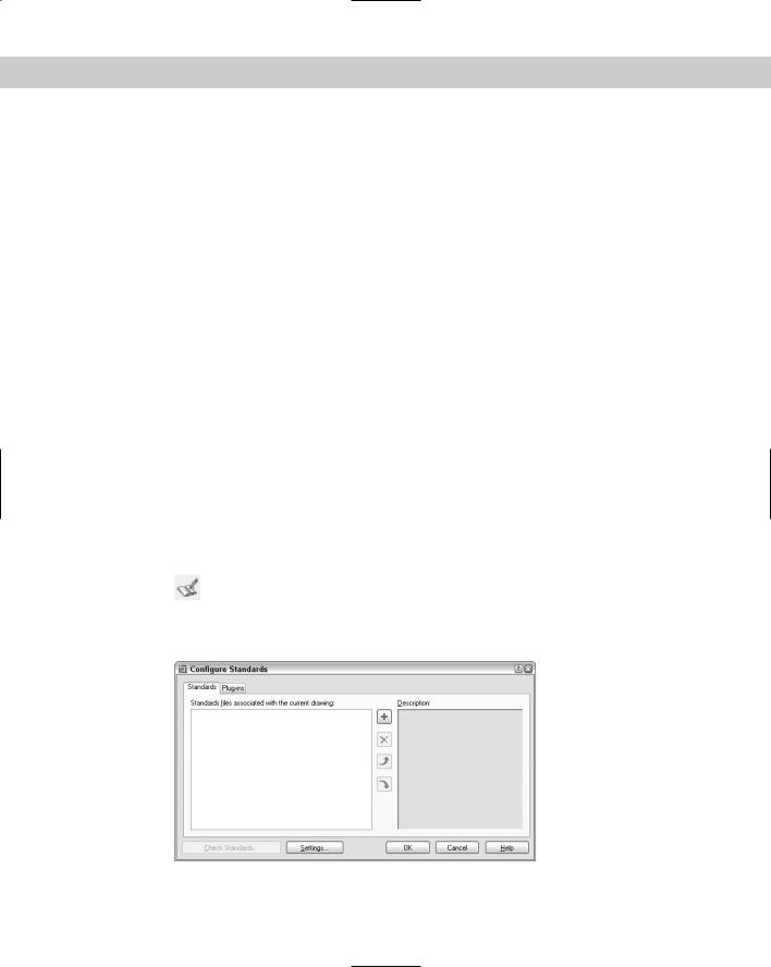
2.On the Standards tab of the Configure Standards dialog box, shown in Figure 26-10, click the + button.
Figure 26-10: Use the Configure Standards dialog box to associate a standards file with a drawing.
Chapter 26 Keeping Control of Your Drawings |
797 |
3.In the Select Standards File dialog box, choose the standards file you want to use and click Open. You can associate more than one standards file with the drawing. Just continue to click the + button and choose more standards files.
4.Click the Plug-ins tab and click any standards you don’t want to check. (All four — Dimension Styles, Layers, Linetypes, and Text Styles — are initially set to be checked. Afterward, the choices you make persist for future standard checks until you change them.)
5.Click OK to close the Configure Standards dialog box and return to your drawing.
Tip |
If you use a template to start new drawings, open the template and associate the standards |
|
file with your template. Then, every drawing that you start based on the template is associ- |
|
ated with the standards file. |
|
Checking a drawing against standards |
|
To check a drawing against its associated standards file, choose Check Standards from the |
|
CAD Standards toolbar to start the CHECKSTANDARDS command (or choose Tools |
|
CAD Standards Check) and open the Check Standards dialog box, shown in Figure 26-11. |
Tip |
If you just finished associating a standards file with a drawing, you can click Check Standards |
|
in the Configure Standards dialog box. |
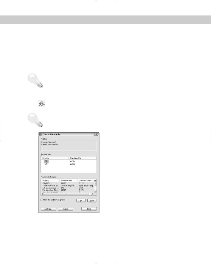
Figure 26-11: The Check Standards dialog box guides you through the process of checking a drawing against a standards file.

798 Part V Organizing and Managing Drawings
The Check Standards dialog box lists all the problems — items in the drawing that don’t match the standards file — that it finds, one by one. Here’s the procedure for using this dialog box:
1.You see the first problem in the problem section of the dialog box.
2.Use the Replace With section to choose a replacement for the nonstandard item. This section contains all eligible replacements according to the standards file.
3.Look at the Preview of Changes section to see how the replacement will affect your drawing.
4.To make the replacement and standardize your drawing, click the Fix button.
 To ignore the problem and go on to the next one, click the Next button.
AutoCAD continues to display problems that you can fix or ignore. After you’re done, you see the Checking is complete message in the Problem area, along with a short report explaining how all the problems were handled, as shown in Figure 26-12. You can click the Next button again to recheck the drawing.
5. Click Close to return to your drawing.
Figure 26-12: The completed standards check report.
For information on batch checking (checking standards for many drawings at once), see the “Checking standards for multiple drawings” sidebar in this chapter.
When you fix nonstandard objects — for example layers or linetypes with nonstandard names — AutoCAD purges these objects from the drawing. For example, after you change the layer Layer1 to the layer Notes, objects on Layer1 are changed to the layer Notes and Layer1 is purged.
Specifying CAD standards settings
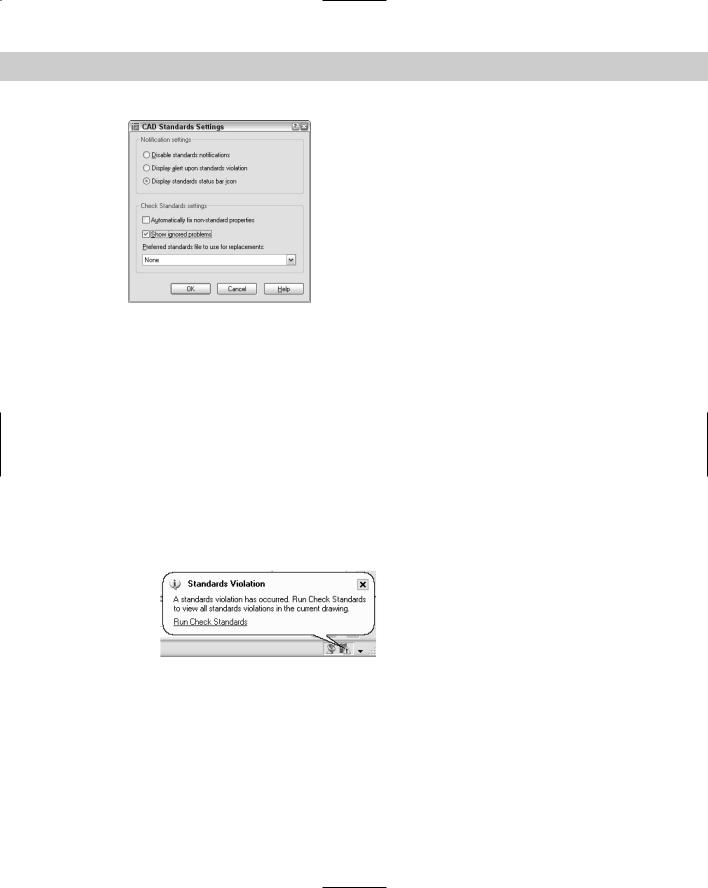
You can specify how the CAD standards feature functions to provide real-time notification and automatic repair. To specify CAD standards settings, choose Tools CAD Standards Configure and click the Settings button to open the CAD Standards Settings dialog box, as shown in Figure 26-13. (You can also click Settings from the Check Standards dialog box.)
Chapter 26 Keeping Control of Your Drawings |
799 |
Figure 26-13: Use the CAD Standards Settings dialog box to specify how you want CAD standards checking to work.
In the top section, Notification Settings, choose one of the following:
Disable standards notifications: No real-time notification of standards violations. You can still check standards using the Check Standards dialog box at any time.
Display alert upon standards violation: Displays a message if your drawing is associated with a standards file and you make a change that puts the drawing in noncompliance with the standards file.
Display standards status bar alert icon: Displays an icon on the AutoCAD status bar, as shown in Figure 26-14. The icon has an exclamation point if there is a nonstandard object in the drawing. A balloon appears to notify you that a standards violation has occurred. Click the Run Check Standards text or the icon to open the Check Standards dialog box so that you can fix the problems.
Figure 26-14: The status bar alert of a standards violation.
In the bottom section, Check Standards Settings, check Automatically Fix Non-standard Properties to fix non-compliant drawings automatically. Automatic fixing only applies to a situation where a drawing object has a name that matches a standard but has different properties. For example, if a standards file contains a layer named OBJ that has a blue color and the current drawing has an object on the OBJ layer that is red, the object will be changed to blue, to match the color of the OBJ layer in the standards file.
800 Part V Organizing and Managing Drawings
Check Show Ignored Problems to display any problems that were not fixed in the standards check report.
From the Preferred Standards File to Use for Replacements drop-down list, choose a standards file to use by default in the Replace With section of the Check Standards dialog box. This standards file is only used if you choose to automatically fix nonstandard properties and the associated standards file for the drawing does not provide a suitable replacement.
Checking standards for multiple drawings
What do you do if you want to check standards for hundreds of drawings at once? For this scenario, AutoCAD has created Batch Standards Checking, shown here. Here’s how to use the Batch Standards Checker:
1.From the Windows taskbar, choose Start Programs Autodesk AutoCAD 2005 Batch Standards Checker. The Batch Standards Checker, shown in the following figure, appears.
2.On the Drawings tab, click the + button and select the drawings you want to include. Click Open. After you click Open, you can click the + button again and add drawings from a different folder. Use the Delete button to delete drawings and the Move Up and Move Down buttons to change the order of the drawings. If you also want to check external references, check the Check External References of Listed Drawings check box.
3.On the Standards tab, choose to check each drawing against its associated standards file if you have associated standards files for all your drawings. Otherwise, choose to check the drawings against the standards file(s) that you select. To select a standards file, click the + button, choose a standards file (.dws), and click Open.
4.On the Plug-ins tab, choose the standards that you want to check. This tab is the same as the Plug-ins tab of the Configure Standards dialog box, discussed earlier in this section.
Chapter 26 Keeping Control of Your Drawings |
801 |
5.Click Save on the Batch Standards Checker toolbar. In the Batch Standards Checker — File Save dialog box, save the standards check file. A standards check file (.chx) contains information about which drawings and standards files you’re using for the batch standards check. AutoCAD gives the file a default name, but you can change the name if you wish.
6.To start checking the drawings, click Start Check on the Batch Standards Checker toolbar. (You can click Stop Check to stop the check any time during its progress.)
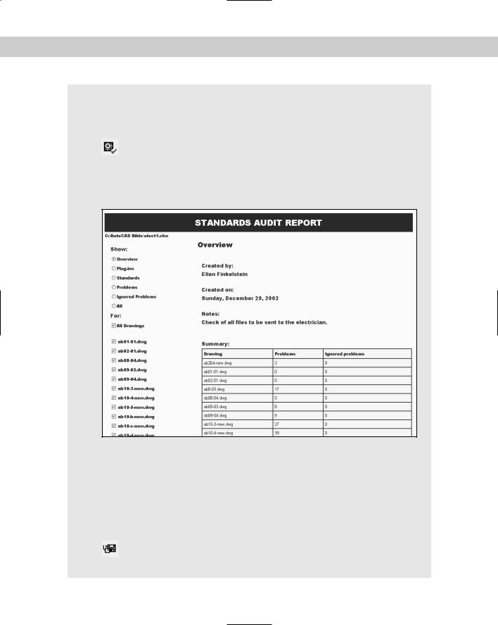
The Batch Standards Checker starts checking your drawings. Click the Progress tab to see what is happening, if you want. When the checking is done, your Standards Audit Report is displayed. An example is shown here. Standards Audit Reports appear in your Internet browser.
Here are some other features of the Batch Standards Checker:
To open an existing standards check file, click Open on the Batch Standards Checker toolbar. Choose the check file and click Open.
To view an existing batch audit report, open an existing standards check file and click the View Report button on the toolbar.
Use the Notes tab of the Batch Standards Checker to add notes that will appear on the batch audit report.
You can export the Standards Audit Report to HTML format. Click Export Report on the Batch Standards Checker toolbar. You can then easily e-mail the report to others.
You can also copy and paste the table portion of the report into a spreadsheet program.
802 Part V Organizing and Managing Drawings
Translating layers
If you receive drawings from clients or colleagues, you might find that their layer system doesn’t suit yours. Manually translating one set of layers to another to fit your layer standards could be a tedious job. The LAYTRANS command changes the layers of objects by specifying sets of “from” and “to” layers. For example, you can change all objects on layer1 to the layer objects. Use this feature to maintain layer standards.
The layer translation feature is not available in AutoCAD LT.
Setting up the layer mapping
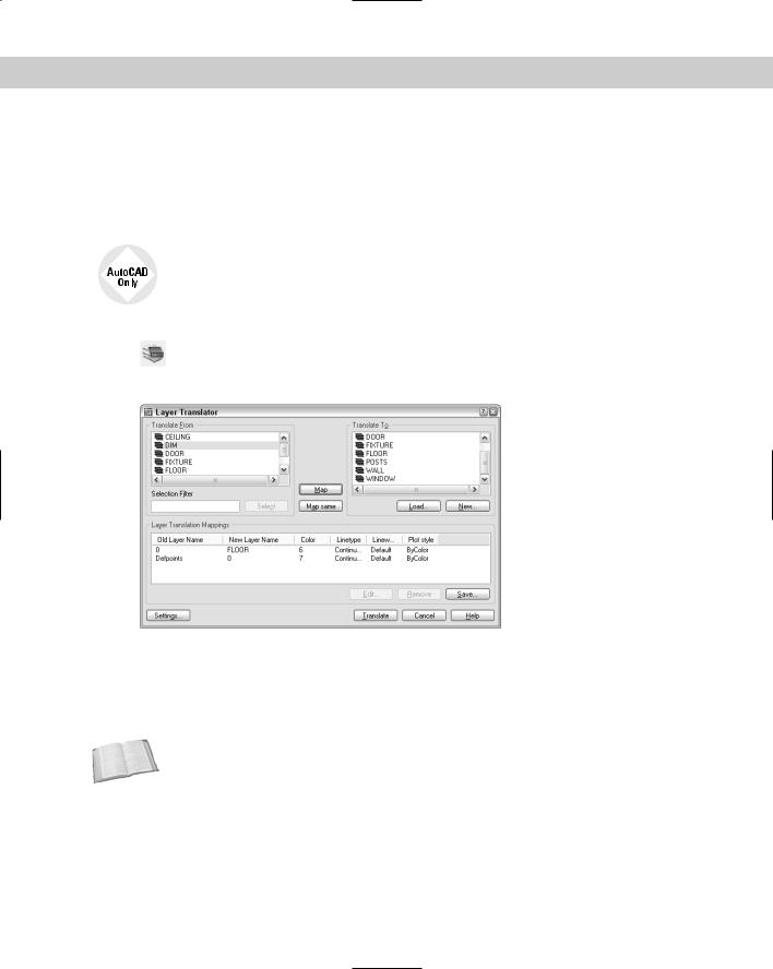
To translate one layer to another, choose Layer Translate from the CAD Standards toolbar (or choose Tools CAD Standards Layer Translator). The Layer Translator, shown
in Figure 26-15, opens.
Figure 26-15: The Layer Translator.
On the Translate From side of the dialog box, you see the layers in the drawing. (Layers with a white icon to their left are not being used. You can right-click them and choose Purge Layers to purge them from the drawing.) Select layers by clicking them. You can select multiple layers.
You can type a selection filter in the Selection Filter text box to select certain layers.
Cross- |
See Chapter 11 for more information about filtering layer lists. |
Reference |
|
To load existing layers, choose Load. In the Select Drawing File dialog box, you can choose a drawing, a drawing template, or a drawing standards file. Click Open. The layers from that file now appear in the Translate To list. Select the layer to which you want to translate.
To define a new layer, choose New. In the New Layer dialog box, type a name for the new layer and specify its color, linetype, lineweight, and plot style. Click OK.
To specify how layers are translated, map layers in the current drawing (listed in the Translate From list) to the layers you want to convert to (listed in the Translate To list). Select a layer
Chapter 26 Keeping Control of Your Drawings |
803 |
in the Translate From list, select a layer in the Translate To list, and click Map. The mapping appears below in the Layer Translation Mappings list. Finally, you’re ready to translate your layers. Click Translate, and AutoCAD takes care of the rest. All objects on the Translate From layers are now on the Translate To layers. The translation process also purges unused layers from the drawing.
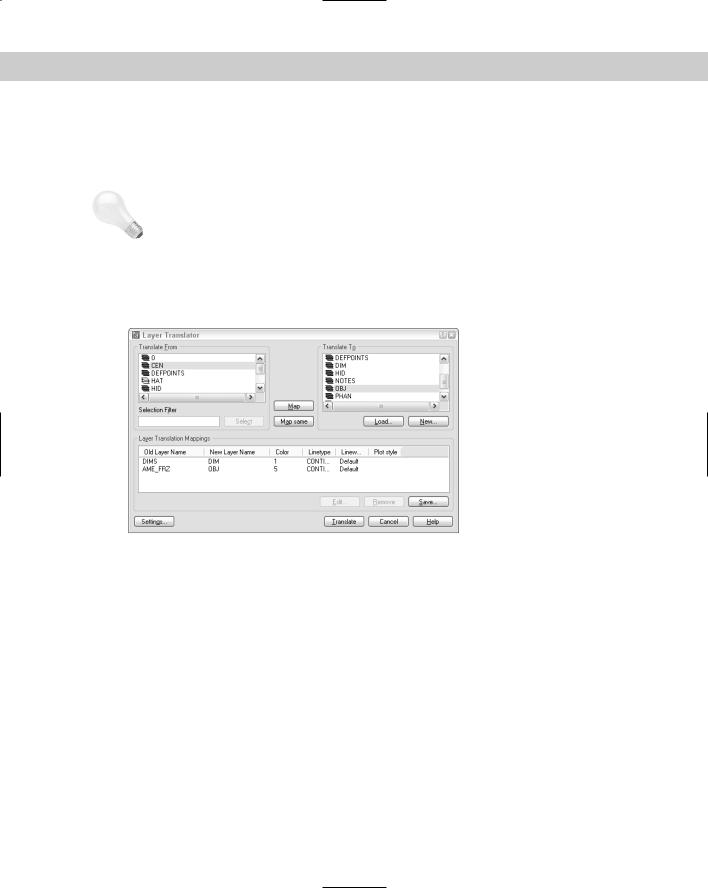
Tip You can select more than one layer from the Translate From list by pressing Ctrl for each additional layer. You can select a contiguous group of layers by clicking the first layer in the group, holding Shift and selecting the last layer in the group. Then, from the Translate To list, select the layer that you want to map that group of layers to and click Map. You can also quickly map all layers with the same name by choosing Map Same.
Figure 26-16 shows an example of mapping where two layers in the current drawing will be mapped to new layers.
Figure 26-16: The Layer Translator helps you change layers to keep to your CAD standards.
Managing layer translations
After you create your mappings, you can edit, remove, or save them:
To edit a mapping, select it and click Edit. In the Edit Layer dialog box, you can choose a new layer, color, linetype, lineweight, or plot style.
To remove a mapping, select it and click Remove.
To save a mapping, click Save. You can choose to save a mapping as a drawing standards file (.dws) or as an actual drawing file (.dwg). Type a filename, choose a location, and click Save. (If you don’t save your layer mapping, AutoCAD prompts you to do so.)
Click Settings to customize the translation process. Here are your options:
•The first two options in the Settings dialog box force objects to take on their layer’s assigned color and linetype. Check these two settings to enforce consistency in your layer properties.
•The Translate Objects in Blocks item determines whether layer mappings are applied to objects within blocks. See Chapter 18 for more about blocks.

804 Part V Organizing and Managing Drawings
•Check Write Transaction Log to create a .log file in the same folder as the drawing you’re translating (the current drawing). The log file lists the details of the translation and can help you troubleshoot problems later.
•Check Show Layer Contents When Selected to help you figure out which objects are on which layers. If you check this item and then select a layer translation in the Translate From or Layer Translation Mappings list, only objects on that layer are shown.
After you finish specifying the translation settings, click OK to close the Settings dialog box.
On the |
The drawings used in the following Step-by-Step exercise on managing CAD standards, |
CD-ROM |
ab26-e.dwg and ab26-e.dws, are in the Drawings folder on the CD-ROM. |
STEP-BY-STEP: Managing CAD Standards
1.Open ab26-e.dwg from the CD-ROM.
2.Save the file as ab26-03.dwg in your AutoCAD Bible folder.
3.Click the Linetype Control drop-down list on the Object Properties toolbar. Notice the Borderx2, Centerx2, Hiddenx2, and Phantom2 linetypes.
4.Right-click any toolbar and choose CAD Standards to open the CAD Standards toolbar. Choose Configure Standards from the toolbar.
5.In the Configure Standards dialog box, click the + button. Find and choose ab26-e.dws, a drawing standards file, on the CD-ROM. Click Open to associate ab26-e.dws with ab26-03.dwg.
6.In the same dialog box, click Check Standards to open the Check Standards dialog box.
7.The first standards problem, Layer ‘AME_FRZ’ Name is non-standard, is listed in the Problem box. Click the Next button to ignore this problem.
8.The next problem is Layer ‘CEN’ Properties are non-standard. Choose CEN from the Replace With list and click the Fix button.
9.Continue to make the following changes, clicking the Fix button after each one:
LINETYPE |
BORDERX2 |
BORDER |
LINETYPE |
CENTERX2 |
CENTER |
LINETYPE |
HIDDENX2 |
HIDDEN |
LINETYPE |
PHANTOM2 |
PHANTOM |
TEXTSTYLE |
ZONE |
ROMAND |
TEXTSTYLE |
TECHNIBOLD |
ROMANS |
10.The Checking Complete dialog box appears with a summary of the standards check. Click OK.
11.Click Close.
12.Open the Linetype Control drop-down list again. All the “x2” linetypes have been purged.
13. Click Layer Translate on the CAD Standards toolbar.

Chapter 26 Keeping Control of Your Drawings |
805 |
14.On the right side of the Layer Translator dialog box, click Load. From the Files of Type drop-down list, choose Standards (*.dws). Choose ab26-c.dws, the same standards file you used previously in this exercise and click Open.
15.In the Translate From box, click CEN. Hold down the Ctrl key and click HAT.
16.In the Translate To box, click HID.
17.Click Map. This will map the layers CEN and HAT to the HID layer.
18.Click Translate to translate the mappings.
19.At the message asking if you want to save mapping information, click No. All objects on the CEN and HAT layers are now on the HID layer.
20.In the Standard Violations Alert dialog box that warns you that there is an object that isn’t standards compliant, click Don’t Fix. (You see this dialog box because, in Step 7, you chose not to fix one layer.)
21.Save your drawing.
The Communication Center
The Communication Center feature notifies you about updates, product support, tips, articles, and so on. An icon at the right end of the status bar connects you to the Communication Center.
When new information or updates are available, a bubble appears from the status bar to notify you, as shown in Figure 26-17.
Figure 26-17: The Communication Center notification appears to let you know that new information or updates are available.
To access the information, click the icon or the Click Here text to open the Communication Center window, shown in Figure 26-18. From this window, you can click any link to access its source on the Internet.
Figure 26-18: Click any item to access it on the
Autodesk Web site.