

- •Foreword
- •Preface
- •Is This Book for You?
- •How This Book Is Organized
- •How to Use This Book
- •Doing the Exercises
- •Conventions Used in This Book
- •What the Icons Mean
- •About the CD-ROM
- •Other Information
- •Contacting the Author
- •Acknowledgments
- •Contents at a Glance
- •Contents
- •Getting Acquainted with AutoCAD and AutoCAD LT
- •Starting AutoCAD and AutoCAD LT
- •Creating a New Drawing
- •Using the AutoCAD and AutoCAD LT Interface
- •Creating Your First Drawing
- •Saving a Drawing
- •Summary
- •Creating a New Drawing from a Template
- •Working with Templates
- •Opening a Drawing with Default Settings
- •Opening an Existing Drawing
- •Using an Existing Drawing as a Prototype
- •Saving a Drawing Under a New Name
- •Summary
- •The Command Line
- •Command Techniques
- •Of Mice and Pucks
- •Getting Help
- •Summary
- •Typing Coordinates
- •Displaying Coordinates
- •Picking Coordinates on the Screen
- •Locating Points
- •Summary
- •Unit Types
- •Drawing Limits
- •Understanding Scales
- •Inserting a Title Block
- •Common Setup Options
- •The MVSETUP Command
- •Summary
- •Using the LINE Command
- •Drawing Rectangles
- •Drawing Polygons
- •Creating Construction Lines
- •Creating Rays
- •Summary
- •Drawing Circles
- •Drawing Arcs
- •Creating Ellipses and Elliptical Arcs
- •Making Donuts
- •Placing Points
- •Summary
- •Panning
- •The ZOOM Command
- •Aerial View
- •Named Views
- •Tiled Viewports
- •Snap Rotation
- •User Coordinate Systems
- •Isometric Drawing
- •Summary
- •Editing a Drawing
- •Selecting Objects
- •Summary
- •Copying and Moving Objects
- •Using Construction Commands
- •Creating a Revision Cloud
- •Hiding Objects with a Wipeout
- •Double-Clicking to Edit Objects
- •Grips
- •Editing with the Properties Palette
- •Selection Filters
- •Groups
- •Summary
- •Working with Layers
- •Changing Object Color, Linetype, and Lineweight
- •Working with Linetype Scales
- •Importing Layers and Linetypes from Other Drawings
- •Matching Properties
- •Summary
- •Drawing-Level Information
- •Object-Level Information
- •Measurement Commands
- •AutoCAD’s Calculator
- •Summary
- •Creating Single-Line Text
- •Understanding Text Styles
- •Creating Multiline Text
- •Creating Tables
- •Inserting Fields
- •Managing Text
- •Finding Text in Your Drawing
- •Checking Your Spelling
- •Summary
- •Working with Dimensions
- •Drawing Linear Dimensions
- •Drawing Aligned Dimensions
- •Creating Baseline and Continued Dimensions
- •Dimensioning Arcs and Circles
- •Dimensioning Angles
- •Creating Ordinate Dimensions
- •Drawing Leaders
- •Using Quick Dimension
- •Editing Dimensions
- •Summary
- •Understanding Dimension Styles
- •Defining a New Dimension Style
- •Changing Dimension Styles
- •Creating Geometric Tolerances
- •Summary
- •Creating and Editing Polylines
- •Drawing and Editing Splines
- •Creating Regions
- •Creating Boundaries
- •Creating Hatches
- •Creating and Editing Multilines
- •Creating Dlines
- •Using the SKETCH Command
- •Digitizing Drawings with the TABLET Command
- •Summary
- •Preparing a Drawing for Plotting or Printing
- •Creating a Layout in Paper Space
- •Working with Plot Styles
- •Plotting a Drawing
- •Summary
- •Combining Objects into Blocks
- •Inserting Blocks and Files into Drawings
- •Managing Blocks
- •Using Windows Features
- •Working with Attributes
- •Summary
- •Understanding External References
- •Editing an Xref within Your Drawing
- •Controlling Xref Display
- •Managing Xrefs
- •Summary
- •Preparing for Database Connectivity
- •Connecting to Your Database
- •Linking Data to Drawing Objects
- •Creating Labels
- •Querying with the Query Editor
- •Working with Query Files
- •Summary
- •Working with 3D Coordinates
- •Using Elevation and Thickness
- •Working with the User Coordinate System
- •Summary
- •Working with the Standard Viewpoints
- •Using DDVPOINT
- •Working with the Tripod and Compass
- •Getting a Quick Plan View
- •Shading Your Drawing
- •Using 3D Orbit
- •Using Tiled Viewports
- •Defining a Perspective View
- •Laying Out 3D Drawings
- •Summary
- •Drawing Surfaces with 3DFACE
- •Drawing Surfaces with PFACE
- •Creating Polygon Meshes with 3DMESH
- •Drawing Standard 3D Shapes
- •Drawing a Revolved Surface
- •Drawing an Extruded Surface
- •Drawing Ruled Surfaces
- •Drawing Edge Surfaces
- •Summary
- •Drawing Standard Shapes
- •Creating Extruded Solids
- •Drawing Revolved Solids
- •Creating Complex Solids
- •Sectioning and Slicing Solids
- •Using Editing Commands in 3D
- •Editing Solids
- •Listing Solid Properties
- •Summary
- •Understanding Rendering
- •Creating Lights
- •Creating Scenes
- •Working with Materials
- •Using Backgrounds
- •Doing the Final Render
- •Summary
- •Accessing Drawing Components with the DesignCenter
- •Accessing Drawing Content with Tool Palettes
- •Setting Standards for Drawings
- •Organizing Your Drawings
- •Working with Sheet Sets
- •Maintaining Security
- •Keeping Track of Referenced Files
- •Handling Errors and Crashes
- •Managing Drawings from Prior Releases
- •Summary
- •Importing and Exporting Other File Formats
- •Working with Raster Images
- •Pasting, Linking, and Embedding Objects
- •Summary
- •Sending Drawings
- •Opening Drawings from the Web
- •Creating Object Hyperlinks
- •Publishing Drawings
- •Summary
- •Working with Customizable Files
- •Creating Keyboard Shortcuts for Commands
- •Customizing Toolbars
- •Customizing Tool Palettes
- •Summary
- •Creating Macros with Script Files
- •Creating Slide Shows
- •Creating Slide Libraries
- •Summary
- •Creating Linetypes
- •Creating Hatch Patterns
- •Summary
- •Creating Shapes
- •Creating Fonts
- •Summary
- •Working with Menu Files
- •Customizing a Menu
- •Summary
- •Introducing Visual LISP
- •Getting Help in Visual LISP
- •Working with AutoLISP Expressions
- •Using AutoLISP on the Command Line
- •Creating AutoLISP Files
- •Summary
- •Creating Variables
- •Working with AutoCAD Commands
- •Working with Lists
- •Setting Conditions
- •Managing Drawing Objects
- •Getting Input from the User
- •Putting on the Finishing Touches
- •Summary
- •Understanding Local and Global Variables
- •Working with Visual LISP ActiveX Functions
- •Debugging Code
- •Summary
- •Starting to Work with VBA
- •Writing VBA Code
- •Getting User Input
- •Creating Dialog Boxes
- •Modifying Objects
- •Debugging and Trapping Errors
- •Moving to Advanced Programming
- •A Final Word
- •Installing AutoCAD and AutoCAD LT
- •Configuring AutoCAD
- •Starting AutoCAD Your Way
- •Configuring a Plotter
- •System Requirements
- •Using the CD with Microsoft Windows
- •What’s on the CD
- •Troubleshooting
- •Index
Chapter 22 Viewing 3D Drawings 645
13.Right-click and choose Preset Views NW Isometric.
14.Press Esc to exit 3D orbit mode.
Don’t save your drawing.
Using Tiled Viewports
As you learned in Chapter 8, you can create multiple viewports to view your drawing at different zooms and pans. Tiled viewports are very helpful in 3D drawings as well. Although you can, and should, save UCSs and views, if you find yourself switching back and forth between two to four viewpoints, try creating two to four viewports with the different viewpoints and UCSs in them. The only disadvantage is that you have less screen real estate for each viewpoint.
Defining a Perspective View
The original command for defining views with perspective from any angle and distance was DVIEW. The newer 3D Orbit feature is easier to use than DVIEW, but you may still find it helpful for its precise ways of defining a view. (Also, 3D Orbit is not available in AutoCAD LT, but DVIEW is.)
Like 3D orbit, DVIEW uses the metaphor of a camera. There is a camera point — where you are standing — and a target point — what you are looking at. By defining these two points, you can create either close-up or distance views, much as you would with the zoom or panoramic lens of a camera.
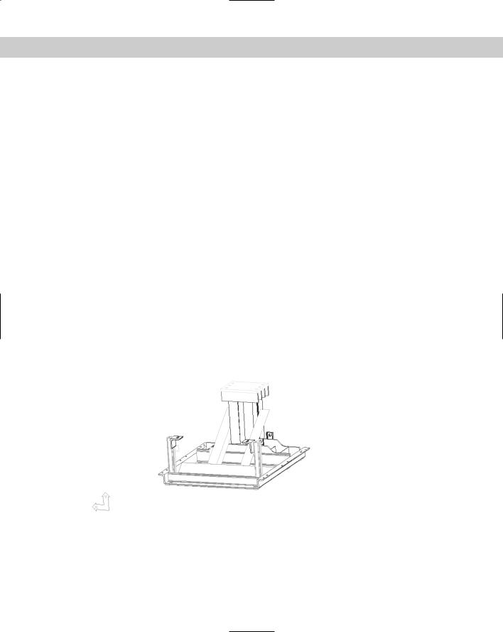
The DVIEW command creates both parallel and perspective views. Figure 22-29 shows a parallel view. Notice the side brackets. Figure 22-30 shows a perspective view of the same model. The side brackets appear to approach each other as they become more distant.
Figure 22-29: A parallel view created with DVIEW.
Thanks to Robert Mack of the Dexter Company, Fairfield, Iowa, for this
drawing, a base housing for an industrial washing machine.

646 Part IV Drawing in Three Dimensions
Figure 22-30: A perspective view of the same model.
|
Using DVIEW |
|
To create a perspective view, type dview on the command line. At the Select objects or |
|
<use DVIEWBLOCK>: prompt, select the objects you want to include in the process of defin- |
|
ing the perspective view. |
|
You should select as few objects as you need to visualize the final result if you have a com- |
|
plex drawing. If you want to select the entire drawing, type all even if the current view |
|
doesn’t display the entire drawing. |
|
Press Enter if you don’t want to choose any objects. The command substitutes a block called |
|
dviewblock, which is a simple house. You can use the house to set your perspective view. |
Tip |
If you want, you can create your own block and name it dviewblock. Create it with X, Y, and Z |
|
dimensions of 1. When you press Enter at the Select objects or <use DVIEWBLOCK>: |
|
prompt, the command looks for dviewblock and uses it to display the results of the perspective |
|
view settings. |
Understanding the DVIEW options
DVIEW comes with a bewildering array of options that you use to specify the angle and distance of the view. To use these options, start the DVIEW command and select the objects you want to view or press Enter. You see the following prompt:
Enter option [CAmera/TArget/Distance/POints/PAn/Zoom/TWist/CLip/Hide/Off/Undo]:
You use these options to define the perspective view, as explained in the following sections.
Camera
Use the Camera option to specify the angle of the camera, which represents where you’re standing. You need to specify the angle from the X axis in the XY plane and the angle from the XY plane. This is very similar to the way you specify a view using the DDVPOINT command, explained earlier in this chapter.

Chapter 22 Viewing 3D Drawings 647
When you choose this option, by right-clicking and choosing Camera, you see the following prompt:
Specify camera location, or enter angle from XY plane, or [Toggle (angle in)] <35.2644>:
The default angle is based on the current view when you start DVIEW. If you know the angle from the XY plane, you can just type it in. You can also move the cursor vertically to dynamically see the results. The view constantly changes as you move the cursor, moving up over your objects as you move the cursor up, and down as you move the cursor down. Move the cursor in one direction and then keep it still for a second to see the full effect.
However, moving the cursor horizontally changes the angle from the X axis in the XY plane. It can be confusing to change both angles at once so you can limit the effect of your cursor movement to one angle. You do this with the Toggle suboption.
Right-click and choose Toggle (angle in) to see the next prompt of the Camera option:
|
Specify camera location, or enter angle in XY plane from X axis, or |
|
[Toggle (angle from)] |
|
<66.12857>: |
|
Now, your cursor affects only the angle from the X axis. Move the cursor horizontally to see |
|
your objects rotate around you at a constant altitude. Press Enter when you like what you |
|
see, or you can type in an angle. |
Tip |
If you want to set the angle in the XY plane first and limit the effect of cursor movement to that |
|
change, you need to use the Toggle suboption to get to the Enter angle in XY plane |
|
from X axis: prompt. After you set the angle in the XY plane, the suboption ends. Start the |
|
Camera option again to set the angle from the XY plane. |
Target
The Target option (right-click and choose Target) works exactly like the Camera option except that it defines the angles for the target of your viewpoint — what you would see through the camera lens. However, the angles are relative to the camera position. If you’ve already set the camera angles, the target angles default to those created by drawing a straight line from the camera angle through 0,0,0. As with the Camera option, use the Toggle suboption to switch between the two angles you need to specify.
Distance
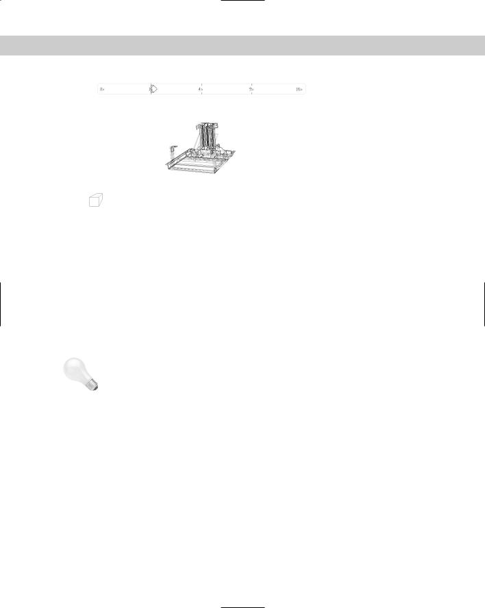
The Distance option is very important because using it turns on perspective mode. Before you use this option, the views you see are parallel views. When you use the Distance option, you see a slider bar at the top of the screen, as shown in Figure 22-31. After you choose a distance, the perspective mode icon replaces the UCS icon if your UCS display is set to 2D. (Choose View Display UCS Icon Properties.)
The command line displays the Specify new camera-target distance <3.0000>: prompt. You can type a distance from the camera to the target or use the slider bar. Move the cursor to the right to zoom out. Moving the cursor to 4x is equivalent to using the ZOOM command and typing 4x . Move the cursor to the left of 1x to zoom in. The zoom factor is relative to the current display so that 1x leaves the zoom unchanged.
You can also type a distance in drawing units.
648 Part IV Drawing in Three Dimensions
Figure 22-31: Using the Distance option turns on perspective mode and displays a slider bar.
|
Points |
|
You can use the Points option (right-click and choose Points) to define the camera and target. |
|
The command line displays the Specify target point <0.3776, -0.1618, 1.0088>: |
|
prompt. The default target point, which is different for each drawing, is the center of the cur- |
|
rent view. You see a rubber-band line from the target point, which you can use to get your |
|
bearings when choosing a new target point. You can also type a coordinate. At the Specify |
|
camera point <-1.5628, 0.9420, 2.2787>: prompt, pick or type a point. You can use |
|
the rubber-band line stretching from the target so that you can visualize the camera and tar- |
|
get points. |
|
Because it’s difficult to know what 3D points you’re picking, you should use an object snap or |
|
XYZ point filters to pick points. |
Tip |
Although it is common to choose a target point on one of the objects in your drawing, often |
|
you want the camera point to be off the objects so that you’re looking at the objects from a |
|
certain distance and angle. To pick the camera point, choose Format Point Style (before |
|
starting DVIEW) and choose an easily visible point style. Decide what elevation you want, |
|
type elev , and set a new elevation. From plan view, choose Point from the Draw toolbar |
|
and pick a point. The point is created on the current elevation. Then use the Node object |
|
snap to snap to the point when specifying the camera point in the Points option. |
|
Even though the Points option sets both distance and angle for the camera and target points, |
|
you still need to use the Distance option to turn on perspective mode. |
|
Pan |
|
You cannot use the regular PAN or ZOOM commands within DVIEW, so DVIEW has its own |
|
Pan and Zoom options. At the Specify displacement base point: prompt, pick any |
|
point. At the Specify second point: prompt, pick the point to which you want the first |
|
point to pan. The model moves the distance and direction indicated by an imaginary line |
|
from the base point to the second point. |
Chapter 22 Viewing 3D Drawings 649
Zoom
The Zoom option displays the same slider bar you see with the Distance option, explained previously. If perspective mode is not on, you see the Specify zoom scale factor <1>: prompt, which works like the Distance option slider bar. If perspective mode is on, you see the Specify lens length <50.000mm>: prompt. A shorter lens length, such as 35mm, zooms you out, giving a wider angle view. A longer lens length, such as 70mm, zooms you in, giving a narrower angle view.
Note |
Although the prompt shows a default in the form 50.000mm, you can only type in a number. |
|
Omit the mm. |
Twist
The Twist option turns your objects around in a circle parallel to the current view you have defined. The default is 0 (zero) degrees, which is no twist. Assuming your current view looks at the objects right-side up, 180 degrees turns the objects upside down, as if you had turned the camera in your hands upside down. You see a rubber-band line from the center of the view, which you can use to pick a twist point, or you can type in an angle.
Clip
The Clip option enables you to create front and back planes that clip off the view. Objects in front of the front clipping plane or behind the back clipping plane are not displayed. You can use the front clipping plane to clip off a wall in front of the camera, letting you see through the wall to the objects beyond — a kind of CAD x-ray vision. Use the back clipping plane when you want to exclude objects in the distance from your perspective view. The clipping planes are always perpendicular to the line of sight, so you only need to set their distance from the target point.
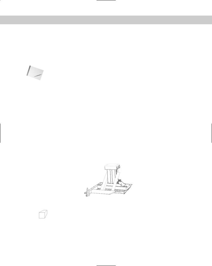
Compare Figure 22-32 to Figure 22-30. In Figure 22-32, the front posts and brackets have been clipped so that they no longer obscure the rest of the model.
Figure 22-32: This model has a front clipping plane that hides the front of the model. Compare it to Figure 22-30.
650 Part IV Drawing in Three Dimensions
When you choose the Clip option, you see the Enter clipping option [Back/Front/Off] <Off>: prompt. Specify Back or Front to set the back or front clipping planes. Specify Off to turn off all previously defined clipping planes.
Note When you use the Distance option to create a perspective view, the option automatically turns on a front clipping plane at the camera point.
When you specify the Front suboption, the command line responds with the Specify distance from target or [set to Eye(camera)/ON/OFF] <2.5682>: prompt. Specify Eye to set the clipping plane at the camera point. You can define the clipping plane by typing in a distance or using the slider bar that appears at the top of your screen. As you move the cursor on the slider bar, stop to let the drawing redraw so you can see the result.
When you specify the Back suboption, the command line displays the Specify distance from target or [ON/OFF] <-5.5826>: prompt. Specify On or Off to turn the clipping plane on or off, or specify the distance as for the front clipping plane.
Hide
The Hide option performs a hide, just like the HIDE command, letting you clearly see the results of the view you’ve created.
Off
The Off option turns off perspective mode and returns you to a parallel view. Otherwise, when you leave DVIEW after going into perspective mode, your drawing retains the perspective view until you change the view — for example, with VPOINT. Until then, you cannot pick points on the screen or use object snaps, which can be very frustrating. This option enables you to exit from DVIEW in the normal viewing mode.
Undo
The Undo option undoes the effect of the last DVIEW option. You can undo through all the changes you have made in DVIEW.
On the |
The drawing used in the following Step-by-Step exercise on creating perspective views, |
CD-ROM |
ab22-d.dwg, is in the Drawings folder on the CD-ROM. |
STEP-BY-STEP: Creating Perspective Views
1.Open ab22-d.dwg from the CD-ROM.
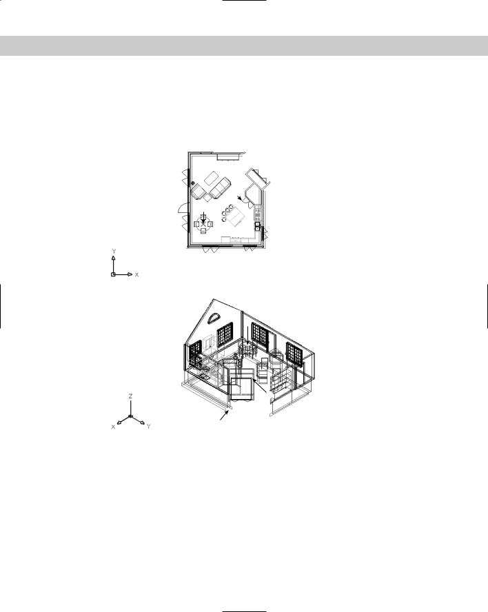
2.Save it as ab22-03.dwg in your AutoCAD Bible folder. This is a portion of a 3D house in plan view, as shown in Figure 22-33. Make sure that OSNAP is on. Set a running object snap set for endpoint and turn off any other object snaps.
3.You want to create a perspective view from approximately 1 to 2 in Figure 22-33. You can see right away that the wall near 1 will need clipping. To get the distance of the clipping plane from the target, choose Tools Inquiry Distance and pick 3 and 4. The pertinent information is Distance = 12'-5 9/16". You may get a slightly different distance. To see the distance information, press F2 to open the Text window.
Chapter 22 Viewing 3D Drawings 651
4.Choose View 3D Views NE Isometric. The result is as shown in Figure 22-34. This is a quick approximation and helps you plan your camera and target points. To test for endpoints, start the LINE command. Place the cursor at 1 in Figure 22-34. The Endpoint SnapTip and marker appear. Place the cursor at 2, the top of the table leg. You should see the Endpoint SnapTip and marker. Press Esc to cancel the LINE command without drawing a line.
Figure 22-33: A 3D house in plan view.
1Thanks to Andrew Wilcox of Virtual Homes, Inc., Hammonds Plains, Nova Scotia, Canada, for this drawing.
3
4
2
2
1
3
4 5
Figure 22-34: The NE isometric view of the house.
5.Type dview . At the Select objects or <use DVIEWBLOCK>: prompt, type all .
Press Enter to end object selection.
6.At the main DVIEW prompt, right-click and choose Points. At the Specify target
point <14'-5 15/16", 21'-9 3/8", 6'-1 1/4">: prompt, pick the endpoint at 2 in Figure 22-34. At the Specify camera point <14'-6 15/16", 21'-10 3/8", 6'-2 1/4">: prompt, pick the endpoint at 1.
7.Right-click and choose Distance. At the Specify new camera-target distance <20'-10 15/16">: prompt, move the cursor to 4x on the slider bar. Take your hand off the mouse to let the drawing redraw until you can see the result. Pick at the 4x mark. Notice the perspective view icon.