

- •Foreword
- •Preface
- •Is This Book for You?
- •How This Book Is Organized
- •How to Use This Book
- •Doing the Exercises
- •Conventions Used in This Book
- •What the Icons Mean
- •About the CD-ROM
- •Other Information
- •Contacting the Author
- •Acknowledgments
- •Contents at a Glance
- •Contents
- •Getting Acquainted with AutoCAD and AutoCAD LT
- •Starting AutoCAD and AutoCAD LT
- •Creating a New Drawing
- •Using the AutoCAD and AutoCAD LT Interface
- •Creating Your First Drawing
- •Saving a Drawing
- •Summary
- •Creating a New Drawing from a Template
- •Working with Templates
- •Opening a Drawing with Default Settings
- •Opening an Existing Drawing
- •Using an Existing Drawing as a Prototype
- •Saving a Drawing Under a New Name
- •Summary
- •The Command Line
- •Command Techniques
- •Of Mice and Pucks
- •Getting Help
- •Summary
- •Typing Coordinates
- •Displaying Coordinates
- •Picking Coordinates on the Screen
- •Locating Points
- •Summary
- •Unit Types
- •Drawing Limits
- •Understanding Scales
- •Inserting a Title Block
- •Common Setup Options
- •The MVSETUP Command
- •Summary
- •Using the LINE Command
- •Drawing Rectangles
- •Drawing Polygons
- •Creating Construction Lines
- •Creating Rays
- •Summary
- •Drawing Circles
- •Drawing Arcs
- •Creating Ellipses and Elliptical Arcs
- •Making Donuts
- •Placing Points
- •Summary
- •Panning
- •The ZOOM Command
- •Aerial View
- •Named Views
- •Tiled Viewports
- •Snap Rotation
- •User Coordinate Systems
- •Isometric Drawing
- •Summary
- •Editing a Drawing
- •Selecting Objects
- •Summary
- •Copying and Moving Objects
- •Using Construction Commands
- •Creating a Revision Cloud
- •Hiding Objects with a Wipeout
- •Double-Clicking to Edit Objects
- •Grips
- •Editing with the Properties Palette
- •Selection Filters
- •Groups
- •Summary
- •Working with Layers
- •Changing Object Color, Linetype, and Lineweight
- •Working with Linetype Scales
- •Importing Layers and Linetypes from Other Drawings
- •Matching Properties
- •Summary
- •Drawing-Level Information
- •Object-Level Information
- •Measurement Commands
- •AutoCAD’s Calculator
- •Summary
- •Creating Single-Line Text
- •Understanding Text Styles
- •Creating Multiline Text
- •Creating Tables
- •Inserting Fields
- •Managing Text
- •Finding Text in Your Drawing
- •Checking Your Spelling
- •Summary
- •Working with Dimensions
- •Drawing Linear Dimensions
- •Drawing Aligned Dimensions
- •Creating Baseline and Continued Dimensions
- •Dimensioning Arcs and Circles
- •Dimensioning Angles
- •Creating Ordinate Dimensions
- •Drawing Leaders
- •Using Quick Dimension
- •Editing Dimensions
- •Summary
- •Understanding Dimension Styles
- •Defining a New Dimension Style
- •Changing Dimension Styles
- •Creating Geometric Tolerances
- •Summary
- •Creating and Editing Polylines
- •Drawing and Editing Splines
- •Creating Regions
- •Creating Boundaries
- •Creating Hatches
- •Creating and Editing Multilines
- •Creating Dlines
- •Using the SKETCH Command
- •Digitizing Drawings with the TABLET Command
- •Summary
- •Preparing a Drawing for Plotting or Printing
- •Creating a Layout in Paper Space
- •Working with Plot Styles
- •Plotting a Drawing
- •Summary
- •Combining Objects into Blocks
- •Inserting Blocks and Files into Drawings
- •Managing Blocks
- •Using Windows Features
- •Working with Attributes
- •Summary
- •Understanding External References
- •Editing an Xref within Your Drawing
- •Controlling Xref Display
- •Managing Xrefs
- •Summary
- •Preparing for Database Connectivity
- •Connecting to Your Database
- •Linking Data to Drawing Objects
- •Creating Labels
- •Querying with the Query Editor
- •Working with Query Files
- •Summary
- •Working with 3D Coordinates
- •Using Elevation and Thickness
- •Working with the User Coordinate System
- •Summary
- •Working with the Standard Viewpoints
- •Using DDVPOINT
- •Working with the Tripod and Compass
- •Getting a Quick Plan View
- •Shading Your Drawing
- •Using 3D Orbit
- •Using Tiled Viewports
- •Defining a Perspective View
- •Laying Out 3D Drawings
- •Summary
- •Drawing Surfaces with 3DFACE
- •Drawing Surfaces with PFACE
- •Creating Polygon Meshes with 3DMESH
- •Drawing Standard 3D Shapes
- •Drawing a Revolved Surface
- •Drawing an Extruded Surface
- •Drawing Ruled Surfaces
- •Drawing Edge Surfaces
- •Summary
- •Drawing Standard Shapes
- •Creating Extruded Solids
- •Drawing Revolved Solids
- •Creating Complex Solids
- •Sectioning and Slicing Solids
- •Using Editing Commands in 3D
- •Editing Solids
- •Listing Solid Properties
- •Summary
- •Understanding Rendering
- •Creating Lights
- •Creating Scenes
- •Working with Materials
- •Using Backgrounds
- •Doing the Final Render
- •Summary
- •Accessing Drawing Components with the DesignCenter
- •Accessing Drawing Content with Tool Palettes
- •Setting Standards for Drawings
- •Organizing Your Drawings
- •Working with Sheet Sets
- •Maintaining Security
- •Keeping Track of Referenced Files
- •Handling Errors and Crashes
- •Managing Drawings from Prior Releases
- •Summary
- •Importing and Exporting Other File Formats
- •Working with Raster Images
- •Pasting, Linking, and Embedding Objects
- •Summary
- •Sending Drawings
- •Opening Drawings from the Web
- •Creating Object Hyperlinks
- •Publishing Drawings
- •Summary
- •Working with Customizable Files
- •Creating Keyboard Shortcuts for Commands
- •Customizing Toolbars
- •Customizing Tool Palettes
- •Summary
- •Creating Macros with Script Files
- •Creating Slide Shows
- •Creating Slide Libraries
- •Summary
- •Creating Linetypes
- •Creating Hatch Patterns
- •Summary
- •Creating Shapes
- •Creating Fonts
- •Summary
- •Working with Menu Files
- •Customizing a Menu
- •Summary
- •Introducing Visual LISP
- •Getting Help in Visual LISP
- •Working with AutoLISP Expressions
- •Using AutoLISP on the Command Line
- •Creating AutoLISP Files
- •Summary
- •Creating Variables
- •Working with AutoCAD Commands
- •Working with Lists
- •Setting Conditions
- •Managing Drawing Objects
- •Getting Input from the User
- •Putting on the Finishing Touches
- •Summary
- •Understanding Local and Global Variables
- •Working with Visual LISP ActiveX Functions
- •Debugging Code
- •Summary
- •Starting to Work with VBA
- •Writing VBA Code
- •Getting User Input
- •Creating Dialog Boxes
- •Modifying Objects
- •Debugging and Trapping Errors
- •Moving to Advanced Programming
- •A Final Word
- •Installing AutoCAD and AutoCAD LT
- •Configuring AutoCAD
- •Starting AutoCAD Your Way
- •Configuring a Plotter
- •System Requirements
- •Using the CD with Microsoft Windows
- •What’s on the CD
- •Troubleshooting
- •Index
850 Part V Organizing and Managing Drawings
Pasting, Linking, and Embedding Objects
To maximize the data you have in your drawing and other documents, you can insert objects from other applications into your drawing. For example, you may have a description of your drawing in a word processing application or a table in a spreadsheet. You can use the Windows Clipboard to share data between applications.
Cross- |
In Chapter 18, I explain how to use the Windows clipboard to copy and move material from |
Reference |
one drawing to another. Chapter 13 includes a discussion of several techniques for import- |
|
|
|
ing text into your drawing. |
You can insert data (text or images) created with other applications into a drawing in three ways:
Embed the object if you want to have the capability of returning to the source application to edit the object. When you double-click the object, the source application opens so that you can edit the object.
Paste the object when you don’t need any connection with the source application — perhaps you want to be able to edit it or you just want to display it.
Link the object when you want to retain a permanent link to the source file so that when the source file is changed the change is updated in your drawing.
You can use the Clipboard to move material from one application to another and take advantage of the special options for pasting, linking, and embedding data. Linking and embedding are often referred to as OLE — Object Linking and Embedding. You can also use drag-and-drop between applications.
The instructions that follow assume that the source application (the application that contains the data you want to insert) is also a Windows application.
Embedding objects into a drawing
You have three ways to embed data from other applications. Each method has its advantages and disadvantages.
Here’s the first way:
1.From your drawing, choose Insert OLE Object to open the Insert Object dialog box, shown in Figure 27-10. This starts the INSERTOBJ command. (The entries listed in this dialog box depend on the applications you have installed on your computer.)
2.If you want to create a new file in the other application, choose Create New. Choose the application you want to use from the Object Type list, and click OK. The other application opens, so you can create the new data. When you’re done, choose File Update from the other application’s menu. (This menu item can vary, depending on the application.) Click the Close button at the top-right corner of the application to close it and return to your drawing. If the OLE Properties dialog box appears, specify how you want the object to appear and click OK. The new file is inserted.
3.If you want to choose an existing file, choose Create from File. Click Browse to find the file. Click Open. You return to the Insert Object file where you can choose Link to link the data (described in the next section of this chapter). Choose OK. The file appears at the top-left corner of your screen with handles that you can use to move and/or resize the object.

Chapter 27 Working with Other Applications |
851 |
Figure 27-10: The Insert Object dialog box.
Here’s the second way:
New
Feature
1.Open the source application, select the data, and copy it to the Clipboard. (Click Copy on the Standard toolbar or choose Edit Copy.) Leave the source application open.
2.If your drawing is open, switch to it by choosing its button on the task bar. Otherwise, open it.
3.In your drawing, choose Edit Paste Special.
4.In the Paste Special dialog box, choose the first option, which lets you embed the object as an object of the source application. Click OK.
5.You can now close the other application.
The third way to insert data is to use drag-and-drop:
1.If your drawing is not open, open it. Open the drawing where you want to embed the data.
2.Open the source application and select the data.
3.Press Ctrl and click the selected data again, holding down the mouse button.
4.Drag the data to the AutoCAD or AutoCAD LT button on the Windows task bar and continue to hold down the mouse button until your drawing displays.
5.Drag the data to the desired location in your drawing.
Using INSERTOBJ gives you the option of creating a new file on the spot in the other application. You don’t have to keep the other application open when you return to your drawing. Note that you cannot create a link if you’re creating a new file.
Using the Clipboard enables you to insert part of a file — for example, part of a spreadsheet — which can be a great advantage. You need to keep the other application open until you paste the object into your drawing.
You now have better control of the size of text and the plot quality of OLE objects. Choose Tools Options and click the Plot and Publish tab, where you can set the default OLE plot quality. To change the plot quality, select the OLE object and change the quality in the Plot Quality item of the Properties palette. Text is automatically scaled to approximate the size in the original application. To change the text size, select the OLE object and right-click. Choose OLE Text Size. In the OLE Text Size dialog box, you can change the text size by entering a new number in the Text Height text box. Click OK.
852 Part V Organizing and Managing Drawings
OLE objects have a few limitations:
If they’re contained in a block or an external reference, they may not be displayed or plotted.
In certain cases, OLE objects can be printed out only on Windows system printers. You can usually configure your plotter to be the system printer.
OLE objects don’t rotate with your drawing when you use a PLOT rotation. Instead, you could use the system printer’s Landscape setting.
Tip If you don’t mind a few steps, you can sometimes get good results importing large Excel spreadsheets by way of Microsoft Word, as follows: In Excel, use Save As to save the spreadsheet in Text (Tab delimited) format. Insert the file into Word (choose Text Files from the Open dialog box’s Files of Type drop-down list). Select the entire file and choose Table Convert Text to Table. Change the Page Setup to accommodate the large size of the table, using a custom paper size. Format the table if you want. Copy it to the Clipboard. In your drawing, choose Paste on the Standard toolbar.
Tip |
If you try to use HIDE on a 3D model that contains OLE objects, the OLE objects disappear! |
|
The solution is to insert them in paper space. You can then hide the 3D model in one float- |
|
ing viewport and display the OLE object in another. |
Using Paste Special
When you copy data to the Clipboard, it’s stored in several formats, depending on the type of data. You can then choose which format you want to use when you paste it into your drawing, using the PASTESPEC command. Choosing the right format can make a big difference, enabling you to edit the data in your drawing as you wish.
Pasting data into your drawing
To paste data using PASTESPEC, open the source application, select the data, and copy it to the Clipboard. (Click Copy on the Standard toolbar or choose Edit Copy.) Leave the source application open.
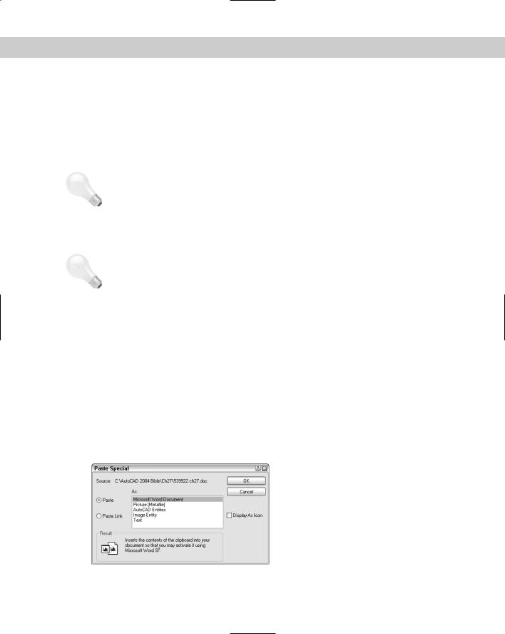
If your drawing is open, choose its button on the task bar. If not, open it. In your drawing, choose Edit Paste Special. This opens the Paste Special dialog box, shown in Figure 27-11. In this figure, you see the options available when you paste in a range of cells from a spreadsheet.
Figure 27-11: The Paste Special dialog box after copying spreadsheet data to the Clipboard.

Chapter 27 Working with Other Applications |
853 |
The choices you see in the As box of the Paste Special dialog box depend on the type of data you copied. In most cases, you can paste as an object of the source application, as a picture (metafile), as a bitmap, and as text. Table 27-3 describes the characteristics of the choices available in the example in Figure 27-11.
Table 27-3: Paste Special Data Types
Data Type |
Characteristics |
|
|
Object of source application |
The object is inserted at the top-left corner of your drawing. |
|
You cannot explode the object, but you can select it and |
|
then resize it or move it using its handles. This is an |
|
embedded object — if you double-click it, the source |
|
application opens, letting you edit the object using the |
|
source application’s tools. |
Picture (Metafile or Enhanced Metafile)
Bitmap
The object is inserted at the top-left corner of your drawing. You cannot explode the object, but you can select it and then resize it or move it using its handles. You cannot edit the object. It maintains good quality when scaled up.
The object is inserted at the top-left corner of your drawing. You cannot explode the object, but you can select it and then resize it or move it using its handles. You cannot edit the object.
AutoCAD Entities |
You get prompts for an insertion point, scale factor, and |
|
rotation angle. You can explode the object into drawing |
|
objects. (Objects were once called entities in AutoCAD and |
|
AutoCAD LT.) Text objects maintain their original font and |
|
formatting. |
Image Entity |
You get prompts for an insertion point, scale factor, and |
|
rotation angle. The object is inserted as a 1×1 unit square — |
|
approximately. It is a kind of bitmap. You can explode it, but |
|
then you lose the image! |
Text |
The object is inserted at the top-left corner of your drawing. |
|
You can explode it, but the text then loses the original |
|
formatting and font. |
|
|
The best choice depends on the type of data you’re pasting. For a spreadsheet, the Picture, Bitmap, and Image Entity choices aren’t useful, but they would be quite appropriate if you were pasting in an image.
Converting objects
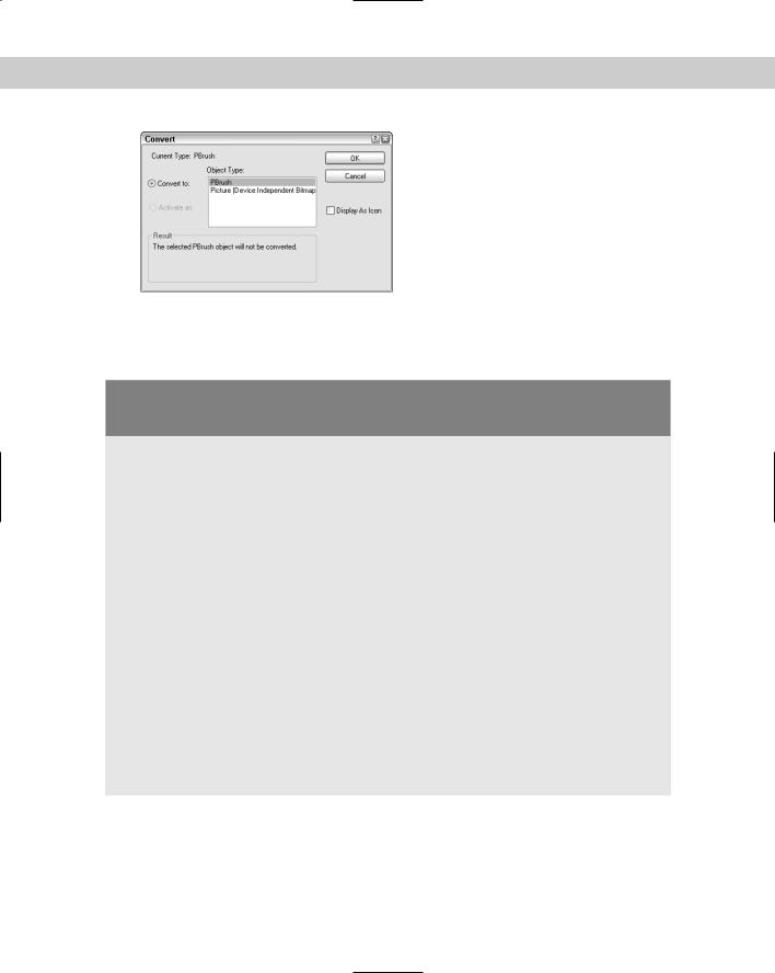
Some pasted objects can be converted to other types of objects. Try right-clicking anywhere on the object that was pasted. If you get a menu, choose an object type and then Convert Picture Object (the menu item varies with the type of object) to open the Convert dialog box, as shown in Figure 27-12. Sometimes no choices are available other than the current image type.
854 Part V Organizing and Managing Drawings
Figure 27-12: Sometimes you can convert one object type into another with the Convert dialog box. Here you can convert a Paintbrush object to a Picture object.
Inserting AutoCAD as an ActiveX component
into PowerPoint
When you insert or paste AutoCAD objects into another document, such as a Word document or PowerPoint presentation, the objects are static images. What if you could display your AutoCAD drawing dynamically, with zooming and panning? You could then show your intended audience all the detail you want.
It turns out that you can. You can use the DWF format (covered in more detail in Chapter 28) and insert it into any version of Word, Excel, or PowerPoint that supports ActiveX components. Viewers need the free Autodesk DWF Viewer, which they can download at www.autodesk.com/ expressviewer. Here are instructions for PowerPoint:
1.Create the DWF file. (See Chapter 28 for instructions.)
2.In PowerPoint, choose a slide layout that gives you room for the DWF file.
3.Choose Insert Object.
4.Click Create New and then choose Autodesk Express Viewer Control. Click OK. You see a box with handles on your slide.
5.If you want, resize or move the box. (If you deselect the box, it disappears. Click inside the box to select it again.)
6.Right-click the box and choose Autodesk Express Viewer Control Objects Properties.
7.In the Autodesk Express Viewer Control Properties dialog box, on the SourcePath tab, type the path to the DWF file or click browse to browse to the file.

Chapter 27 Working with Other Applications |
855 |
8.In your PowerPoint presentation, click the Slide Show View button to enter Slide Show view. You can now pan, zoom, turn layers on and off, print, and so on from within your presentation.
|
|
|
|
|
Pasting drawing objects into another application |
||
|
You can also copy drawing objects to the Clipboard and paste them into another application, |
||
|
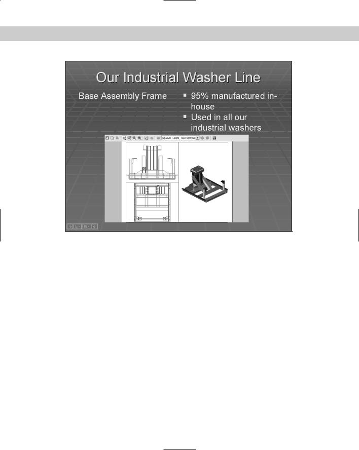
such as a word processing document, a spreadsheet, or a presentation program. Figure 27-13 |
||
|
shows a PowerPoint slide that includes a model from an AutoCAD drawing. To paste drawing |
||
|
objects into another application, select the objects you want to copy. Click Copy on the |
||
|
Standard toolbar. Load the other application (in this case PowerPoint), create a document or |
||
|
file (in this case a slide), and click Paste from the application’s Standard toolbar. |
||
Tip |
|
You can hide a 3D view and copy and paste the view into another application. However, you |
|
|
|
cannot copy and paste a rendered view. To bring a rendered view into another application, |
|
|
|
save it as an image and import it. Chapter 25 covers saving rendered images. You can freeze |
|
|
|
any layers that you don’t want to include, such as dimension and text layers. |
|
856 Part V Organizing and Managing Drawings
Figure 27-13: Placing part of a drawing on a PowerPoint slide.
Linking data
You can insert data from a spreadsheet or text document and maintain a link to the original file, so that if the original file changes the inserted data is updated as well, very similar to xrefs. You could use this feature to place a schedule of doors and windows in an architectural drawing or a bill of materials in a mechanical drawing, for example. You have two ways to link data. You can link data using INSERTOBJ as described earlier in this chapter. You can also use the Clipboard, following these steps:
1.Open the source application, select the data, and copy it to the Clipboard. (Click Copy on the Standard toolbar or choose Edit Copy.)
2.If your drawing is open, choose its button on the task bar. If not, open it.
3.In your drawing, choose Edit Paste Special.
4.In the Paste Special dialog box, choose Paste Link. Click OK.
When you create a link, you don’t have all the format options you do when you simply paste. You can only create a link in the source application’s format.
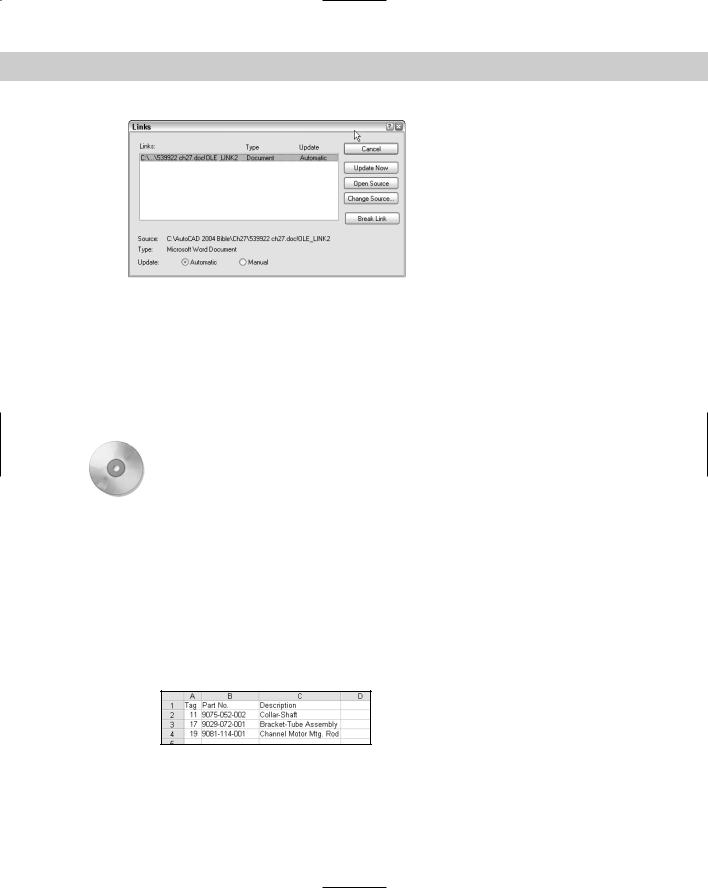
When you open a drawing containing a link, a message appears, asking if you want to update the links. In this way, you can update the links whenever you open the drawing. You can manage links by choosing Edit OLE Links, to open the Links dialog box, shown in Figure 27-14.
Chapter 27 Working with Other Applications |
857 |
Figure 27-14: Use the Links dialog box to manage your links.
The Links dialog box enables you to manually update the links at any time by choosing Update Now. You may want to do this if you know that someone has changed the source of the link during your drawing session. You can also break the link, open the source, or change the source in this dialog box.
Remember that if you give a drawing to someone else, you also need to include any attached images or embedded objects. If the person does not have the source application for an embedded object, you can paste it in as an image.
On the |
The drawing, ab27-c.dwg, and the file, ab27-c.xls, used in the following Step-by-Step |
CD-ROM |
exercise on pasting, linking, and embedding objects are in the Drawings folder on the |
|
CD-ROM. |
To do the following exercise, you need a spreadsheet application. I use Microsoft Excel in this exercise, but you can use Lotus 1-2-3 as well.
STEP-BY-STEP: Pasting, Linking, and Embedding Objects
1.Open ab27-c.dwg from the CD-ROM.
2.Save the file as ab27-04.dwg in your AutoCAD Bible folder.
3.Choose Insert OLE Object. Choose Create New and choose your worksheet application from the list. Click OK. Your worksheet program opens.
4.Create the worksheet shown in Figure 27-15. Adjust the width of the columns to fit the data.
Figure 27-15: Create this worksheet to insert into your AutoCAD drawing.
5.In the spreadsheet application, choose File Update and then choose File Exit. The worksheet appears in the drawing, as shown in Figure 27-16.
858 Part V Organizing and Managing Drawings
Figure 27-16: The spreadsheet inserted into the drawing.
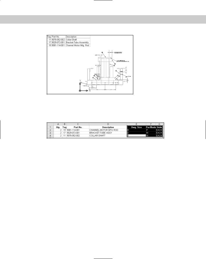
6.Open your spreadsheet application and open ab27-c.xls from the CD-ROM. Select the data in the last three columns, as shown in Figure 27-17. Click Copy on the spreadsheet’s Standard toolbar.
Figure 27-17: Selecting part of a file to insert into your drawing.
7.Leave your spreadsheet open and click the AutoCAD or AutoCAD LT button on the Windows task bar. Choose Edit Paste Special. Although you could insert this as an Excel Worksheet (or object from your spreadsheet application), to try another method, choose AutoCAD (LT) Entities and click OK. Pick an insertion point near the right of the existing OLE object.
8.The spreadsheet comes in as a table object, but very small. Click outside the table to close the MText Editor. Zoom in on the table. Click the lower-right corner of the table and drag its handle down and to the right until the table is the same height as the spreadsheet to its left.
9.Click inside the upper-left cell, press Shift, and click inside the lower-right cell. Choose Properties on the Standard toolbar. In the Properties palette, change the Text Height to .6800. Change the Text Style to WMF-Arial0. (This text style was created when you imported the spreadsheet, to match the original text in the spreadsheet.) Change the Alignment to Middle Center.
10.Choose Edit Paste Special again. Choose Paste Link. Now you can paste only in your spreadsheet’s format. Click OK. Pick an insertion point. Pick the lower-right corner of the spreadsheet and drag its handle down and to the right to enlarge the table.