

Chapter 8 Viewing Your Drawing 151
11.Still in the dialog box, choose World, click Set Current, and click OK to return to your drawing. The UCS icon and crosshairs return to their familiar angle.
12.To return to the Rotated 45 UCS, choose Tools Named UCS to open the UCS dialog box. Choose Rotated 45 and click Set Current. Click OK to restore the Rotated 45 UCS.
13.Save your drawing.
Tip |
After creating a new, rotated UCS such as the one in the previous exercise, type plan (to start |
|
the PLAN command) and use the Current UCS option to remove the rotation. Now you aren’t |
|
working at an angle in your UCS. To return to the World UCS, type plan again and choose the |
|
World option to return to your drawing’s previous state. |
Isometric Drawing
An isometric drawing is a 2D drawing drawn to look like a 3D drawing. Every child learns how to draw a box that looks three-dimensional. By drawing parallelograms instead of squares, the drawing gives the impression of being in three dimensions. AutoCAD and AutoCAD LT enable you to do the same thing.
Understanding isometric planes
The ISOPLANE (short for isometric plane) command rotates the crosshairs to the special angles required for isometric drawing. You then toggle the ISOPLANE setting from left to right to top to draw on each of the three “planes.” As you do so, the angles of the crosshairs, snap, and grid change to the appropriate angles.
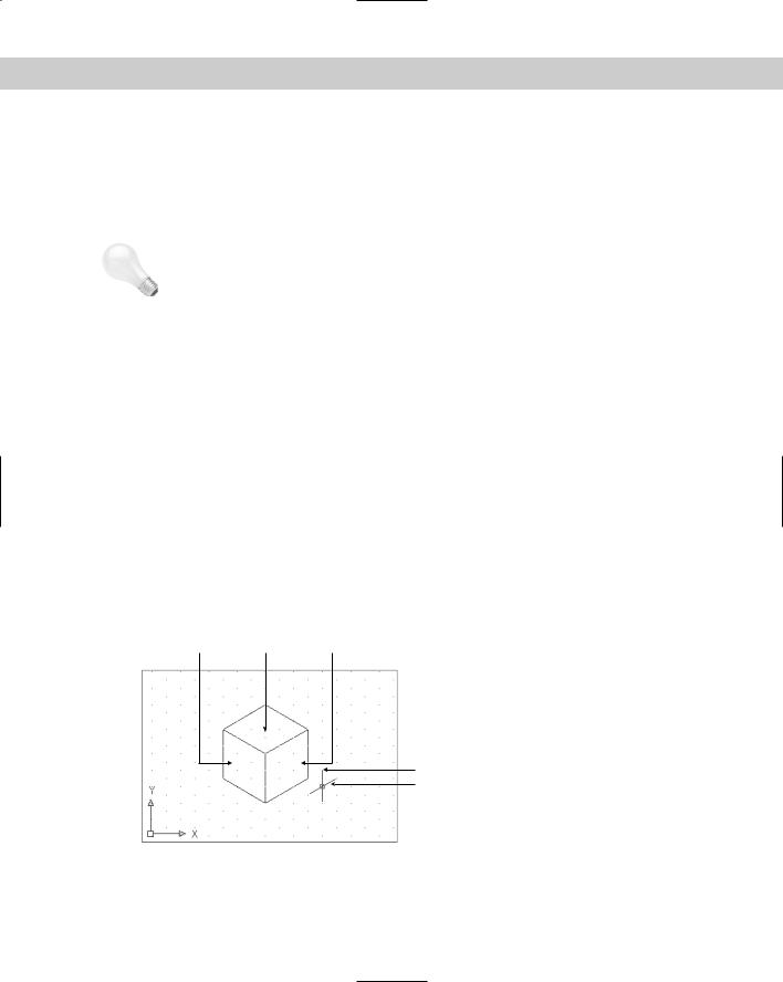
These angles are 30 degrees for the X axis, 90 degrees for the Z axis, and 150 degrees for the Y axis. As you toggle among the planes, you see the crosshairs take on various configurations of these angles. Figure 8-24 shows the standard isometric cube. You can see three sides — left, right, and top. In the figure, the crosshairs are set to the right isometric plane.
Left plane Top plane Right plane
y axis x axis
Figure 8-24: The isometric cube.

152 Part II Drawing in Two Dimensions
|
Isometric drawing is not often used for precise drawing because specifying the exact points |
|
that you need can be difficult. Also, true 3D drawing has mostly supplanted isometric drawing. |
|
It is, however, used for piping work as well as for illustrations. |
Tip |
Use snap points and object snaps as much as possible in an isometric drawing. Also, set the |
|
cursor to 100 percent of the screen to better visualize the isometric planes. (Choose Tools |
|
Options and click the Display tab.) The grid is also a helpful aid. |
Drawing in isometric mode
To start isometric mode, choose Tools Drafting Settings to open the Drafting Settings dialog box. On the Snap and Grid tab, in the Snap Type & Style section, choose Grid Snap (if it is not already selected), and then Isometric Snap. While you’re there, turn on Snap and Grid if you want them on. Click OK. After you’re in isometric mode, press F5 to toggle from plane to plane.
Drawing lines in isometric mode is fairly straightforward if the lines are parallel to one of the isometric plane angles. Circles and arcs in isometric mode must be drawn as ellipses and elliptical arcs. When you’re in isometric mode, the ELLIPSE command has an Isocircle option.
STEP-BY-STEP: Drawing in Isometric Mode
1.Start a new drawing by using the acad.dwt template.
2.Save the drawing in your AutoCAD Bible folder as ab08-04.dwg.
3.Right-click the SNAP button on the status bar and choose Settings. On the Snap and Grid tab, in the Snap Type & Style section, choose Grid Snap (if it is not already selected), and then Isometric Snap.
4.In the Snap section, ensure the Snap Y spacing is set to 0.5 and click Snap On. In the Grid section, ensure the Grid Y spacing is set to 0.5 and click Grid On. Click OK to return to your drawing.
5.Choose Tools Options and click the Display tab. In the Crosshair Size text box, change the cursor size to 100. Click OK.
6.Press F5 until you see the <Isoplane Left> prompt.
7.Do a Zoom Window to zoom into the area covered by the grid.
8.Start the LINE command. Follow the prompts:
Specify first point: Use the coordinate display to choose 3.4641,2, which is a snap point. (It may take you a while to find the point.) Specify next point or [Undo]: Choose 6.4952,0.25. (Press F6 if necessary to get dynamic absolute coordinates.)
Specify next point or [Undo]: Choose 6.4952,1.25. Specify next point or [Close/Undo]: Choose 3.4641,3.
Specify next point or [Close/Undo]: Right-click and choose Close to close the left side of the model. All these points are snap points.
Chapter 8 Viewing Your Drawing 153
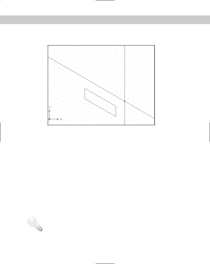
The results are shown in Figure 8-25.
Figure 8-25: The left side of the iron plate. The cursor has been changed to extend to 100 percent of the screen.
9.Press F5 twice until you see <Isoplane Right> on the command line.
10.Start the LINE command again. At the Specify first point: prompt, pick 6.4952,1.25.
Press F6 twice to get dynamic polar coordinates. At the Specify next point or [Undo]: prompt, pick when the coordinates show 2.0000<30. At the Specify next point or [Undo]: prompt, use the polar coordinate display to draw a line of 1.0000<270. At the Specify next point or [Close/Undo]: prompt, draw a line of 2.0000<210. End the LINE command.
11.Press F5 twice until you see <Isoplane Top> on the command line.
12.Start the LINE command. Start the line at 8.2272,2.25, which is a snap point. Draw a line of 3.500<150 and continue another line of 2.000<210. End the LINE command. This completes the box.
13.Choose Ellipse from the Draw toolbar. Right-click and choose Isocircle from the short-
cut menu. At the Specify center of isocircle: prompt, choose 5.1962,3. At the
Specify radius of isocircle or [Diameter]: prompt, type .5 to draw the ellipse. Your drawing should look like Figure 8-26.
14.Change the cursor size back to 5 (%). Save your drawing.
Tip |
Polar coordinate display is very helpful while drawing isometrically. The coordinates are easier |
|
to understand than the unusual absolute snap point coordinates created by ISOPLANE. |

154 Part II Drawing in Two Dimensions
Figure 8-26: The completed iron plate with a hole in it, drawn isometrically.
Summary
In this chapter, you read how to control the display of your drawing. You learned about:
The PAN and ZOOM commands, including real-time pan and zoom and the many ZOOM options
Using Aerial View to pan and zoom
Saving several views of your drawing so that you can retrieve them quickly
Creating tiled viewports for drawing and editing, as well as how to name and display useful viewport configurations
Rotating the snap and grid
Creating a User Coordinate System, including how to save a useful UCS and then set it as current at any time
Setting the snap style to isometric to create isometric drawings, which are 2D drawings that give the appearance of three dimensions
In the next chapter, you discover how to start editing your drawings.
|
|
|