

- •Foreword
- •Preface
- •Is This Book for You?
- •How This Book Is Organized
- •How to Use This Book
- •Doing the Exercises
- •Conventions Used in This Book
- •What the Icons Mean
- •About the CD-ROM
- •Other Information
- •Contacting the Author
- •Acknowledgments
- •Contents at a Glance
- •Contents
- •Getting Acquainted with AutoCAD and AutoCAD LT
- •Starting AutoCAD and AutoCAD LT
- •Creating a New Drawing
- •Using the AutoCAD and AutoCAD LT Interface
- •Creating Your First Drawing
- •Saving a Drawing
- •Summary
- •Creating a New Drawing from a Template
- •Working with Templates
- •Opening a Drawing with Default Settings
- •Opening an Existing Drawing
- •Using an Existing Drawing as a Prototype
- •Saving a Drawing Under a New Name
- •Summary
- •The Command Line
- •Command Techniques
- •Of Mice and Pucks
- •Getting Help
- •Summary
- •Typing Coordinates
- •Displaying Coordinates
- •Picking Coordinates on the Screen
- •Locating Points
- •Summary
- •Unit Types
- •Drawing Limits
- •Understanding Scales
- •Inserting a Title Block
- •Common Setup Options
- •The MVSETUP Command
- •Summary
- •Using the LINE Command
- •Drawing Rectangles
- •Drawing Polygons
- •Creating Construction Lines
- •Creating Rays
- •Summary
- •Drawing Circles
- •Drawing Arcs
- •Creating Ellipses and Elliptical Arcs
- •Making Donuts
- •Placing Points
- •Summary
- •Panning
- •The ZOOM Command
- •Aerial View
- •Named Views
- •Tiled Viewports
- •Snap Rotation
- •User Coordinate Systems
- •Isometric Drawing
- •Summary
- •Editing a Drawing
- •Selecting Objects
- •Summary
- •Copying and Moving Objects
- •Using Construction Commands
- •Creating a Revision Cloud
- •Hiding Objects with a Wipeout
- •Double-Clicking to Edit Objects
- •Grips
- •Editing with the Properties Palette
- •Selection Filters
- •Groups
- •Summary
- •Working with Layers
- •Changing Object Color, Linetype, and Lineweight
- •Working with Linetype Scales
- •Importing Layers and Linetypes from Other Drawings
- •Matching Properties
- •Summary
- •Drawing-Level Information
- •Object-Level Information
- •Measurement Commands
- •AutoCAD’s Calculator
- •Summary
- •Creating Single-Line Text
- •Understanding Text Styles
- •Creating Multiline Text
- •Creating Tables
- •Inserting Fields
- •Managing Text
- •Finding Text in Your Drawing
- •Checking Your Spelling
- •Summary
- •Working with Dimensions
- •Drawing Linear Dimensions
- •Drawing Aligned Dimensions
- •Creating Baseline and Continued Dimensions
- •Dimensioning Arcs and Circles
- •Dimensioning Angles
- •Creating Ordinate Dimensions
- •Drawing Leaders
- •Using Quick Dimension
- •Editing Dimensions
- •Summary
- •Understanding Dimension Styles
- •Defining a New Dimension Style
- •Changing Dimension Styles
- •Creating Geometric Tolerances
- •Summary
- •Creating and Editing Polylines
- •Drawing and Editing Splines
- •Creating Regions
- •Creating Boundaries
- •Creating Hatches
- •Creating and Editing Multilines
- •Creating Dlines
- •Using the SKETCH Command
- •Digitizing Drawings with the TABLET Command
- •Summary
- •Preparing a Drawing for Plotting or Printing
- •Creating a Layout in Paper Space
- •Working with Plot Styles
- •Plotting a Drawing
- •Summary
- •Combining Objects into Blocks
- •Inserting Blocks and Files into Drawings
- •Managing Blocks
- •Using Windows Features
- •Working with Attributes
- •Summary
- •Understanding External References
- •Editing an Xref within Your Drawing
- •Controlling Xref Display
- •Managing Xrefs
- •Summary
- •Preparing for Database Connectivity
- •Connecting to Your Database
- •Linking Data to Drawing Objects
- •Creating Labels
- •Querying with the Query Editor
- •Working with Query Files
- •Summary
- •Working with 3D Coordinates
- •Using Elevation and Thickness
- •Working with the User Coordinate System
- •Summary
- •Working with the Standard Viewpoints
- •Using DDVPOINT
- •Working with the Tripod and Compass
- •Getting a Quick Plan View
- •Shading Your Drawing
- •Using 3D Orbit
- •Using Tiled Viewports
- •Defining a Perspective View
- •Laying Out 3D Drawings
- •Summary
- •Drawing Surfaces with 3DFACE
- •Drawing Surfaces with PFACE
- •Creating Polygon Meshes with 3DMESH
- •Drawing Standard 3D Shapes
- •Drawing a Revolved Surface
- •Drawing an Extruded Surface
- •Drawing Ruled Surfaces
- •Drawing Edge Surfaces
- •Summary
- •Drawing Standard Shapes
- •Creating Extruded Solids
- •Drawing Revolved Solids
- •Creating Complex Solids
- •Sectioning and Slicing Solids
- •Using Editing Commands in 3D
- •Editing Solids
- •Listing Solid Properties
- •Summary
- •Understanding Rendering
- •Creating Lights
- •Creating Scenes
- •Working with Materials
- •Using Backgrounds
- •Doing the Final Render
- •Summary
- •Accessing Drawing Components with the DesignCenter
- •Accessing Drawing Content with Tool Palettes
- •Setting Standards for Drawings
- •Organizing Your Drawings
- •Working with Sheet Sets
- •Maintaining Security
- •Keeping Track of Referenced Files
- •Handling Errors and Crashes
- •Managing Drawings from Prior Releases
- •Summary
- •Importing and Exporting Other File Formats
- •Working with Raster Images
- •Pasting, Linking, and Embedding Objects
- •Summary
- •Sending Drawings
- •Opening Drawings from the Web
- •Creating Object Hyperlinks
- •Publishing Drawings
- •Summary
- •Working with Customizable Files
- •Creating Keyboard Shortcuts for Commands
- •Customizing Toolbars
- •Customizing Tool Palettes
- •Summary
- •Creating Macros with Script Files
- •Creating Slide Shows
- •Creating Slide Libraries
- •Summary
- •Creating Linetypes
- •Creating Hatch Patterns
- •Summary
- •Creating Shapes
- •Creating Fonts
- •Summary
- •Working with Menu Files
- •Customizing a Menu
- •Summary
- •Introducing Visual LISP
- •Getting Help in Visual LISP
- •Working with AutoLISP Expressions
- •Using AutoLISP on the Command Line
- •Creating AutoLISP Files
- •Summary
- •Creating Variables
- •Working with AutoCAD Commands
- •Working with Lists
- •Setting Conditions
- •Managing Drawing Objects
- •Getting Input from the User
- •Putting on the Finishing Touches
- •Summary
- •Understanding Local and Global Variables
- •Working with Visual LISP ActiveX Functions
- •Debugging Code
- •Summary
- •Starting to Work with VBA
- •Writing VBA Code
- •Getting User Input
- •Creating Dialog Boxes
- •Modifying Objects
- •Debugging and Trapping Errors
- •Moving to Advanced Programming
- •A Final Word
- •Installing AutoCAD and AutoCAD LT
- •Configuring AutoCAD
- •Starting AutoCAD Your Way
- •Configuring a Plotter
- •System Requirements
- •Using the CD with Microsoft Windows
- •What’s on the CD
- •Troubleshooting
- •Index
Chapter 23 Creating 3D Surfaces 685
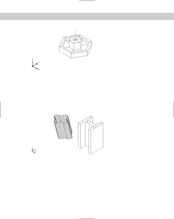
Figure 23-26: The revolved surface.
Drawing an Extruded Surface
A simple way to create a 3D object is to start with a 2D object and extrude it (or thrust it out). In AutoCAD, extruding refers to creating a 3D object from a 2D object. The TABSURF command takes an outline, or profile, which AutoCAD calls a path curve, and extrudes it along a vector that defines the direction and distance of the extrusion. TABSURF creates a 3D polyline mesh. The type of surface created is called a tabulated surface. Figure 23-27 shows two examples of extruded surfaces.
Figure 23-27: Two extruded surfaces created using
TABSURF.
For the I-beam, you could have simply given the 2D polyline profile a thickness and achieved a similar result. However, the extruded surface on the left could only have been created with TABSURF because the extrusion is not perpendicular to the XY plane that contains the 2D polyline profile. TABSURF can extrude a shape in any direction.
When you select the vector object, your pick point determines the direction of the extrusion. AutoCAD starts the extrusion from the end of the vector closest to the pick point.
You use SURFTAB1 to control the number of lines AutoCAD uses to display the curve. If the curve is made up of polyline segments, AutoCAD displays one line at each segment vertex.

686 Part IV Drawing in Three Dimensions
Caution |
Note the I-beam in Figure 23-27. If you create an object by mirroring, stretching, and so on, |
|
you’ll see extra tabulation lines at the separate segments in the polyline definition. If you |
|
want a clean look, you need to draw clean. You might need to use the original shape as a |
|
guide to draw a new polyline on top of the old one, and then erase the original. |
You should use a nonplanar view when using TABSURF to check that you’ve accurately defined the extrusion vector into the third dimension. Any of the preset isometric views will be helpful.
To draw an extruded surface, follow these steps:
On the
CD-ROM
1.Draw the object to extrude — a line, arc, circle, polyline, ellipse, or elliptical arc. This is the path curve.
2.Draw the vector, usually a line. If you use a 2D or 3D polyline, AutoCAD uses an imaginary line from the start point to the endpoint to determine the vector.
3. Choose Tabulated Surface from the Surfaces toolbar.
4. |
At the Select |
object |
for |
path curve: prompt, select the path curve object. |
5. |
At the Select |
object |
for |
direction vector: prompt, select the line you’re using |
for the vector.
The drawing used in the following Step-by-Step exercise on drawing tabulated surfaces, ab23-e.dwg, is in the Drawings folder on the CD-ROM.
STEP-BY-STEP: Drawing Tabulated Surfaces
1.Open ab23-e.dwg from the CD-ROM.
2.Save it as ab23-05.dwg in your AutoCAD Bible folder. You see a tabletop drawn at a Z height of 30. The current elevation is 30. You’re looking at the table from the SE isometric view. OSNAP should be on. Set running object snaps for endpoint, midpoint, and center. The current layer is Const. The drawing is shown in Figure 23-28.
1
Figure 23-28: The tabletop.
Chapter 23 Creating 3D Surfaces 687
3.Start the CIRCLE command. Follow the prompts:
Specify center point for circle or [3P/2P/Ttr (tan tan radius)]:
Choose the From object snap.
_from Base point: Pick the endpoint at 1 in Figure 23-28.
<Offset>: @-1,3
Specify radius of circle or [Diameter]: .75
4.Start the LINE command. At the Specify first point: prompt, choose the Center
object snap of the circle you just drew. At the Specify next point or [Undo]: prompt, type @3,–3,–30 to draw a line flaring out from the circle and going down to the floor. End the LINE command.
5.Choose Tabulated Surface from the Surfaces toolbar. At the Select object for path curve: prompt, select the circle. At the Select object for direction
vector: prompt, select the line. (You can see only the top part of the line, but that’s the part you need to pick.) AutoCAD creates the tabulated surface.
6.Start the MIRROR command. Select the entire leg. Choose the midpoint of the bottom edge of both long sides of the table for the two points of the mirror line.
7.Repeat the MIRROR line and select both legs. Mirror them using the midpoints of the bottom edge of the short sides of the table for the two points of the mirror line.
8.Do a ZOOM Extents to see the entire table.
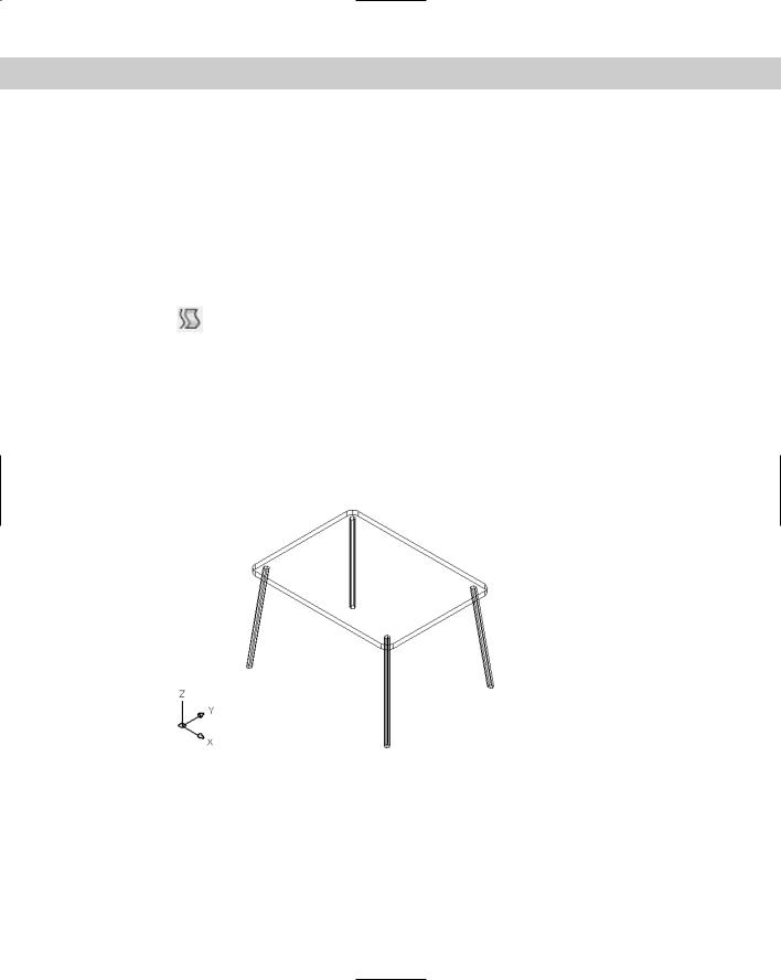
9.Save your drawing. It should look like Figure 23-29.
Figure 23-29: The completed table.
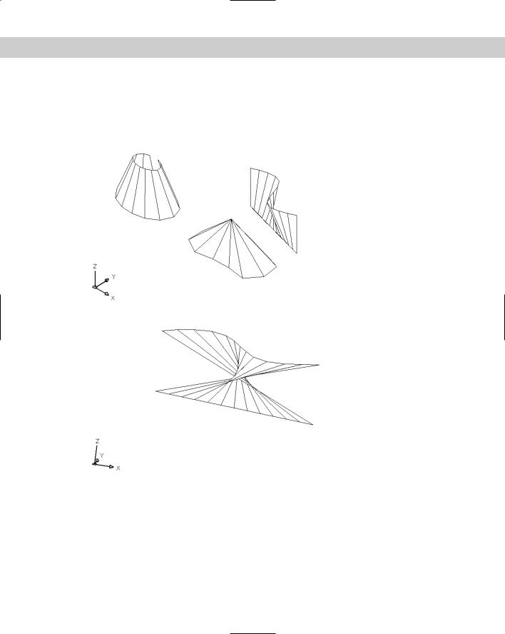
Drawing Ruled Surfaces
If you have two existing objects, you may want to define the surface that would extend between these objects. Use the RULESURF command to create a surface that extends between two objects. The objects can be lines, polylines (2D or 3D), circles, ellipses, elliptical arcs, splines, or points. The two objects must either be both open or both closed. Only one of the two can be a point.
688 Part IV Drawing in Three Dimensions
Use the SURFTAB1 system variable to control the number of lines AutoCAD uses to display the surface. Figure 23-30 shows some ruled surfaces.
The pick points of the two objects affect the resulting curve. If you pick them both on the same side, you get the type of curves shown in Figure 23-30. If you pick them on opposite sides, the curve intersects itself, as shown in Figure 23-31.
Figure 23-30: Ruled surfaces.
Figure 23-31: A self-intersecting ruled surface.
Follow these steps to draw a ruled surface:
1.Draw the two objects for the ruled surface.
2. Choose Ruled Surface from the Surfaces toolbar.
Chapter 23 Creating 3D Surfaces 689
On the
CD-ROM
3.At the Select first defining curve: prompt, choose the first object.
4.At the Select second defining curve: prompt, choose the second object.
The drawing used in the following Step-by-Step exercise on drawing ruled surfaces, ab23-f. dwg, is in the Drawings folder on the CD-ROM.
STEP-BY-STEP: Drawing Ruled Surfaces
1.Open ab23-f.dwg from the CD-ROM.
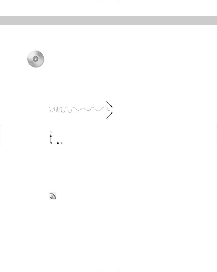
2.Save it as ab23-06.dwg in your AutoCAD Bible folder. You see a spline, as shown in Figure 23-32. In this exercise, you use the spline to draw some drapes.
1
2
Figure 23-32: A spline.
3.Mirror the spline. For the mirror line, turn on ORTHO and use 1 and 2 as shown in Figure 23-32. Don’t delete the original spline.
4.Start the COPY command and select both splines. At the Specify base point or displacement, or [Multiple]: prompt, type 0,0,73 to copy the splines 73
units in the positive Z direction. Press Enter at the Specify second point of displacement or <use first point as displacement>: prompt.
5.Choose View 3D Views SE Isometric.
6.Choose Ruled Surface from the Surfaces toolbar. At the Select first defining curve: prompt, choose the top-right spline near its right endpoint. At the Select
second defining curve: prompt, choose the bottom-right spline near its right endpoint.
7.Repeat the RULESURF command. At the Select first defining curve: prompt, choose the top-left spline near its left endpoint. At the Select second defining curve: prompt, choose the bottom-left spline near its left endpoint.
8.Save your drawing. It should look like Figure 23-33.