


124 Part II Drawing in Two Dimensions
In recent releases, the mechanics behind the display of drawings have significantly improved. It is now rarely necessary to regenerate a drawing.
Panning
Often you cannot see the entire drawing on your screen. You therefore need a way to see the parts of your drawing that are not currently visible.
To pan means to move the display without changing the magnification. The word refers to the expression of panning a camera across a scene or view. You pan to view a different part of your drawing.
Using the PAN command
The PAN command moves the display in the direction and distance you indicate without changing the magnification. Real-time panning moves the drawing as you move the cursor.
|
To pan the drawing, choose Pan Realtime from the Standard toolbar. The cursor |
|
changes to a hand. Place the cursor anywhere in your drawing, click, and drag in the |
|
direction you want the objects to go. Press Shift as you pan to constrain panning to vertical |
|
or horizontal directions. Pan can be used transparently, while you’re in the middle of another |
|
command. |
Tip |
You can pan past the edge of the screen (actually the viewport) in Windows XP. This means |
|
that, when the cursor reaches the edge of the screen, you can continue moving your mouse |
|
in the same direction to continue the pan. |
|
To leave Pan mode, press Esc or Enter or start any command via a menu or toolbar. You can |
|
also right-click to open the shortcut menu shown in Figure 8-1. Use the shortcut menu to exit |
|
Pan mode, switch to real-time Zoom or 3D Orbit (AutoCAD only), or to choose one of the zoom |
|
options listed. |
|
Figure 8-1: The Pan shortcut menu. |
Note |
You can use Microsoft IntelliMouse pointing devices for panning. To pan, click and hold down |
|
the wheel and move your mouse. You see the same panning cursor, the hand, as you do |
|
when you pan by clicking the Pan Real-Time button on the Standard toolbar. However, you |
|
don’t need to press Esc or Enter to leave Pan mode. |
Chapter 8 Viewing Your Drawing 125
Using the scroll bars
You can use the scroll bars to pan vertically and horizontally as you would with any Windows program. However, you can’t easily predict just how much the drawing view will move. Therefore, the scroll bars are less useful than the PAN command.
You can use the scroll bars in three ways:
On the
CD-ROM
Drag the scroll box in the desired direction and in the desired amount.
Click the scroll bar between the scroll box and the up or down arrow.
Click the up or down arrow to move the drawing view slightly.
The drawing used in the following Step-by-Step exercise on panning and scrolling, ab08-a. dwg, is in the Drawings folder on the CD-ROM.
STEP-BY-STEP: Panning and Scrolling
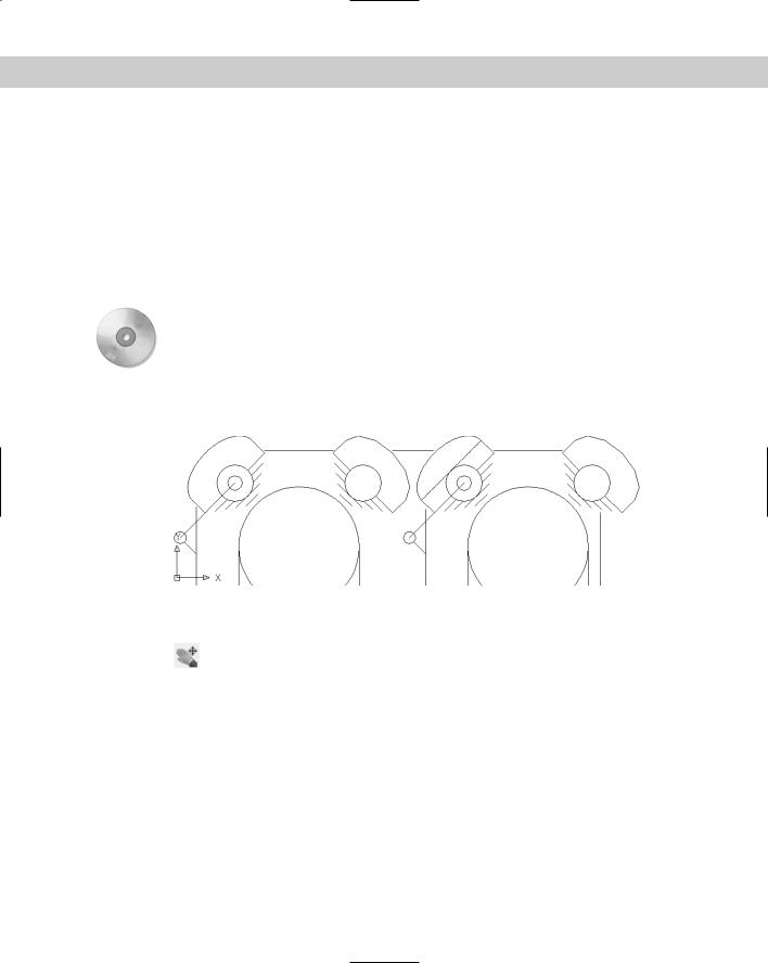
1. Open ab08-a.dwg from the CD-ROM. This is an air compressor, as shown in Figure 8-2.
2
1
Figure 8-2: The air compressor is zoomed in so that you can see only part of the drawing.
2.Choose Pan Realtime from the Standard toolbar. Move the cursor to 1 in Figure 8-2, click, and drag to 2. The air compressor moves up and to the right. (Note that by
the time you get to 2, the display of the air compressor has moved — but you should drag to where 2 was on the screen.) Press Esc.
3.The scroll box of the horizontal scroll bar is all the way to the left. Click anywhere in the scroll bar to the right of the scroll box. The air compressor moves to the left.
4.Click anywhere in the vertical scroll bar between the scroll box and the down arrow at the bottom of the scroll bar. The air compressor moves up as you scroll down.
5.Click the right arrow on the horizontal scroll bar three times. The drawing moves to the left slightly each time. Your drawing should look something like Figure 8-3. You may have a different view if you chose slightly different pan points.
Do not save this drawing.

126 Part II Drawing in Two Dimensions
Figure 8-3: The final view. Your view may be somewhat different.
The ZOOM Command
The ZOOM command enables you to zoom in and out of your drawing, like the zoom lens of a camera. When you zoom in, everything is magnified so that you can see it more easily, but you see less of the entire drawing. When you zoom out, objects look smaller, but you can see more of the drawing. The ZOOM command has several options that make it easy to see just what you need at an appropriate size.
Cross- |
Zooming does not affect the actual size of objects, just as zooming with a camera lens does |
Reference |
not affect the size of the scene you’re viewing. Chapter 9 covers changing the actual size of |
|
|
|
objects (known as scaling). |
When you use real-time zoom, the drawing zooms in and out as you move the cursor. To use real-time zoom, choose Zoom Realtime from the Standard toolbar. The cursor
changes to a magnifying glass with a plus sign on one side and a minus sign on the other side. You determine whether you zoom in or out depending on the movement of the cursor:
To zoom in, click and drag up in the direction of the plus sign.
To zoom out, click and drag down in the direction of the minus sign.
A movement from the middle of the screen to the top edge zooms in 100 percent. A movement from the middle of the screen to the bottom edge zooms out 100 percent.
Tip You can zoom past the edge of the screen (actually the viewport) in Windows XP. As you move the mouse up or down to zoom, when you reach the edge of the viewport, continue to move the mouse in the same direction to continue the zoom in or out.
You can zoom with Microsoft IntelliMouse pointing devices. Rotate the wheel up to zoom in and down to zoom out. There is no Zoom Realtime cursor, and you don’t need to press Esc or Enter to leave zoom mode. You can also double-click the wheel to do a Zoom to the extents of the drawing.

Chapter 8 Viewing Your Drawing 127
Tip |
To control how much you zoom for each incremental movement of the wheel, change the |
|
ZOOMFACTOR system variable. The default is 60. |
|
Right-click to open the shortcut menu to exit Zoom mode, switch to real-time pan or 3D Orbit |
|
(AutoCAD only), or to choose one of the zoom options listed. To end real-time zoom, you can |
|
also press Esc or Enter or start any command via a menu or toolbar. |
Understanding ZOOM options
The Zoom flyout on the Standard toolbar has eight options. The Standard toolbar also has a separate Zoom Previous button. Table 8-1 outlines these Zoom options.
|
Table 8-1: Zoom Options |
|
|
Button Option |
Description |
|
|
Window |
This button lets you define a rectangular window as the boundaries of the new |
|
display. The command prompts you for the two corners of the window. Use |
|
Window to zoom in on any area already displayed in your drawing. When you use |
|
Zoom Window, the command displays everything in the window you specify but |
|
reshapes the display to fit your screen. As a result, you may see objects that were |
|
outside the specified window. You can move the mouse past the drawing area to |
|
define the window past the edge of the screen. |
Dynamic |
Enables you to zoom and pan in one operation. This option is covered in the next |
|
section of this chapter. |
Scale |
Enter a number to scale the display relative to the drawing limits (a kind of absolute |
|
scaling). Enter a number followed by x to scale the display relative to the current |
|
view (relative scaling). Enter a number followed by xp to scale the display relative |
|
to paper space units (discussed in Chapter 17). A number less than 1 (such as 0.5) |
|
reduces the size of the objects on the screen (such as by half). A number greater |
|
than 1 (such as 2) increases the size of the objects on the screen (such as by 2). |
Center |
Lets you specify a new center for the display, and then a new magnification/height. |
|
The current magnification/height is shown in brackets for your reference. Type a |
|
smaller number to increase the magnification, making the objects larger. Type a |
|
larger value to decrease the magnification, making the objects smaller. |
Object |
Lets you zoom in to selected objects. This option is new for AutoCAD 2005 and |
|
AutoCAD LT 2005. |
In |
Uses the Scale option with a value of 2x. See the Scale option. |
Out |
Uses the Scale option with a value of 0.5x. See the Scale option. |
All |
Zooms the display to the greater of the drawing extents or the drawing limits. |
Extents |
Zooms to the outer extents of the drawing. You can also double-click the wheel of |
|
an IntelliMouse pointing device. |
Previous |
Redisplays the most recent display of your drawing. This option has its own button |
|
on the Standard toolbar. |
|
|
128 Part II Drawing in Two Dimensions
ZOOM Dynamic
The Dynamic option of ZOOM enables you to pan and zoom in one operation. The Aerial View (discussed in the next section) offers more sophisticated options, but the simplicity of ZOOM Dynamic is sometimes just what you need.
When you start ZOOM Dynamic, you see the virtual screen area of the drawing in a blue dashed rectangle — the drawing extents or limits, whichever is greater. Your current view is bounded in a green, dashed rectangle. Your mouse cursor changes based on the two modes of ZOOM Dynamic. Each time you click the left mouse button, you switch modes. Here’s how the two modes work:
Pan mode: The box contains an X and can move freely around any displayed area of the drawing.
Zoom mode: The box has an arrow. The left side of the box is fixed at the point where you changed to Zoom mode. As you move the cursor, the box expands or shrinks, letting you zoom to any magnification.
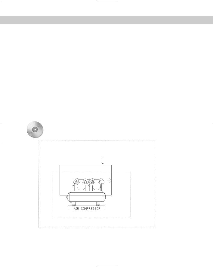
When the view box displays the view that you want, click the right mouse button and choose Enter (or press Enter). The command pans and zooms to show that view. Figure 8-4 shows the screen during a ZOOM Dynamic operation.
On the |
The drawing used in the following Step-by-Step exercise on using ZOOM Dynamic, ab08-b. |
CD-ROM |
dwg, is in the Drawings folder on the CD-ROM. |
 Generated area of drawing
View box in Zoom mode
 Current
view
Figure 8-4: Using ZOOM Dynamic.
Chapter 8 Viewing Your Drawing 129
STEP-BY-STEP: Using ZOOM Options
1.Open ab08-b.dwg from the CD-ROM. This is a drawing of a warehouse, as shown in Figure 8-5.
3
1 2
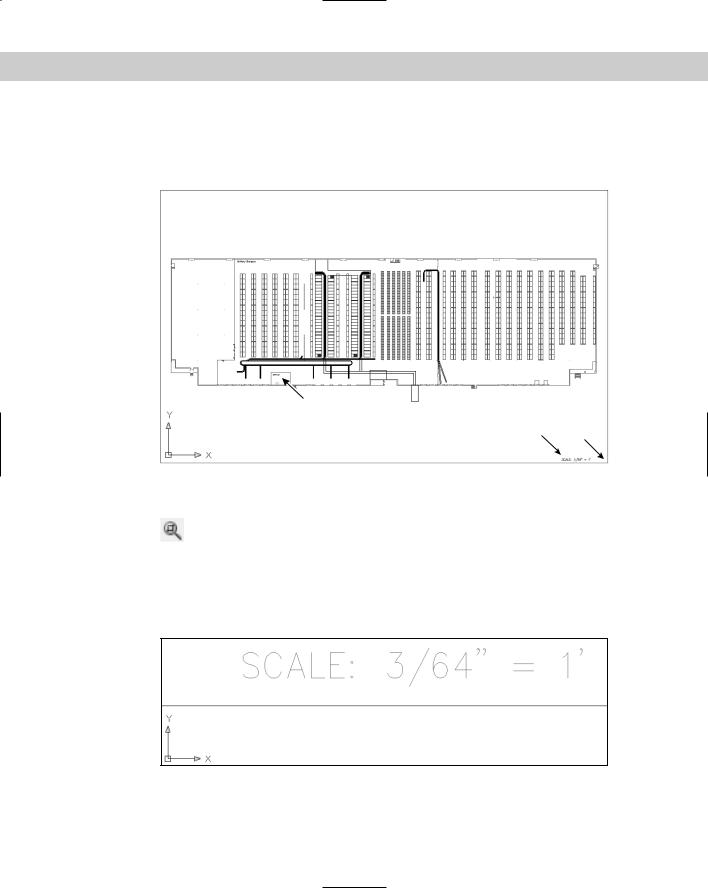
Figure 8-5: A drawing of a large warehouse, with shelving and conveyor belts.
Thanks to Bryan Kelly of ATI Corporation, Fairfield, Iowa, for this drawing.
2.To read the text in the lower-right corner, choose Zoom Window from the Zoom flyout of the Standard toolbar.
3.At the Specify first corner: prompt, pick 1, as shown in Figure 8-5. At the Specify opposite corner: prompt, pick 2. AutoCAD or AutoCAD LT zooms in to display the window you specified, as shown in Figure 8-6.
4. Choose Zoom All from the Zoom flyout of the Standard toolbar.
Figure 8-6: Your display should look approximately like this figure after using ZOOM Window.
130 Part II Drawing in Two Dimensions
5.Choose Zoom Previous from the Standard toolbar. You quickly return to the previous display.
6.Choose Zoom Extents from the Zoom flyout of the Standard toolbar. The drawing fills the screen. In this drawing, the drawing extents are similar to the drawing lim-
its, so that you see little difference between using Zoom All and Zoom Extents.
7.Choose Zoom Center from the Zoom flyout. At the Specify center __point: prompt, pick 3 in Figure 8-5. At the Enter magnification or height
<5315.176>: prompt, type 500 . You zoom in on the office.
8.Choose Zoom Realtime from the Standard toolbar. Place the cursor at the top of the drawing, click, and drag to the bottom of the screen. The display zooms out
about 200 percent.
9.Choose Zoom Scale from the Zoom flyout of the Standard toolbar. Type _2x . The display zooms in, doubling the scale of the view and returning you approximately
to the previous view of the office.
10.Choose Zoom Dynamic from the Zoom flyout. You now see the entire drawing. The current view is shown with a green dashed line. The mouse cursor is a box
with an X in it. You are now in Pan mode. To zoom in on the right side of the warehouse, move the Pan box to the lower-right corner of the warehouse and click with the pick (left) button.
11.You are now in Zoom mode. The Zoom box contains an arrow. Move the mouse to the left to shrink the Zoom box. Notice that the Zoom box is fixed at its left side. When the Zoom box is about half its original size, left-click again.
12.You are back in Pan mode again. Move the Pan box to the bottom-right corner of the warehouse. Right-click and choose Enter to zoom in on this new view. Your display should look approximately like Figure 8-7.
13.Choose Zoom All from the Zoom flyout. Do not save your drawing. If you’re continuing to the next exercise, leave the drawing open.
Figure 8-7: The new view of the drawing after using Zoom Dynamic.