

- •Foreword
- •Preface
- •Is This Book for You?
- •How This Book Is Organized
- •How to Use This Book
- •Doing the Exercises
- •Conventions Used in This Book
- •What the Icons Mean
- •About the CD-ROM
- •Other Information
- •Contacting the Author
- •Acknowledgments
- •Contents at a Glance
- •Contents
- •Getting Acquainted with AutoCAD and AutoCAD LT
- •Starting AutoCAD and AutoCAD LT
- •Creating a New Drawing
- •Using the AutoCAD and AutoCAD LT Interface
- •Creating Your First Drawing
- •Saving a Drawing
- •Summary
- •Creating a New Drawing from a Template
- •Working with Templates
- •Opening a Drawing with Default Settings
- •Opening an Existing Drawing
- •Using an Existing Drawing as a Prototype
- •Saving a Drawing Under a New Name
- •Summary
- •The Command Line
- •Command Techniques
- •Of Mice and Pucks
- •Getting Help
- •Summary
- •Typing Coordinates
- •Displaying Coordinates
- •Picking Coordinates on the Screen
- •Locating Points
- •Summary
- •Unit Types
- •Drawing Limits
- •Understanding Scales
- •Inserting a Title Block
- •Common Setup Options
- •The MVSETUP Command
- •Summary
- •Using the LINE Command
- •Drawing Rectangles
- •Drawing Polygons
- •Creating Construction Lines
- •Creating Rays
- •Summary
- •Drawing Circles
- •Drawing Arcs
- •Creating Ellipses and Elliptical Arcs
- •Making Donuts
- •Placing Points
- •Summary
- •Panning
- •The ZOOM Command
- •Aerial View
- •Named Views
- •Tiled Viewports
- •Snap Rotation
- •User Coordinate Systems
- •Isometric Drawing
- •Summary
- •Editing a Drawing
- •Selecting Objects
- •Summary
- •Copying and Moving Objects
- •Using Construction Commands
- •Creating a Revision Cloud
- •Hiding Objects with a Wipeout
- •Double-Clicking to Edit Objects
- •Grips
- •Editing with the Properties Palette
- •Selection Filters
- •Groups
- •Summary
- •Working with Layers
- •Changing Object Color, Linetype, and Lineweight
- •Working with Linetype Scales
- •Importing Layers and Linetypes from Other Drawings
- •Matching Properties
- •Summary
- •Drawing-Level Information
- •Object-Level Information
- •Measurement Commands
- •AutoCAD’s Calculator
- •Summary
- •Creating Single-Line Text
- •Understanding Text Styles
- •Creating Multiline Text
- •Creating Tables
- •Inserting Fields
- •Managing Text
- •Finding Text in Your Drawing
- •Checking Your Spelling
- •Summary
- •Working with Dimensions
- •Drawing Linear Dimensions
- •Drawing Aligned Dimensions
- •Creating Baseline and Continued Dimensions
- •Dimensioning Arcs and Circles
- •Dimensioning Angles
- •Creating Ordinate Dimensions
- •Drawing Leaders
- •Using Quick Dimension
- •Editing Dimensions
- •Summary
- •Understanding Dimension Styles
- •Defining a New Dimension Style
- •Changing Dimension Styles
- •Creating Geometric Tolerances
- •Summary
- •Creating and Editing Polylines
- •Drawing and Editing Splines
- •Creating Regions
- •Creating Boundaries
- •Creating Hatches
- •Creating and Editing Multilines
- •Creating Dlines
- •Using the SKETCH Command
- •Digitizing Drawings with the TABLET Command
- •Summary
- •Preparing a Drawing for Plotting or Printing
- •Creating a Layout in Paper Space
- •Working with Plot Styles
- •Plotting a Drawing
- •Summary
- •Combining Objects into Blocks
- •Inserting Blocks and Files into Drawings
- •Managing Blocks
- •Using Windows Features
- •Working with Attributes
- •Summary
- •Understanding External References
- •Editing an Xref within Your Drawing
- •Controlling Xref Display
- •Managing Xrefs
- •Summary
- •Preparing for Database Connectivity
- •Connecting to Your Database
- •Linking Data to Drawing Objects
- •Creating Labels
- •Querying with the Query Editor
- •Working with Query Files
- •Summary
- •Working with 3D Coordinates
- •Using Elevation and Thickness
- •Working with the User Coordinate System
- •Summary
- •Working with the Standard Viewpoints
- •Using DDVPOINT
- •Working with the Tripod and Compass
- •Getting a Quick Plan View
- •Shading Your Drawing
- •Using 3D Orbit
- •Using Tiled Viewports
- •Defining a Perspective View
- •Laying Out 3D Drawings
- •Summary
- •Drawing Surfaces with 3DFACE
- •Drawing Surfaces with PFACE
- •Creating Polygon Meshes with 3DMESH
- •Drawing Standard 3D Shapes
- •Drawing a Revolved Surface
- •Drawing an Extruded Surface
- •Drawing Ruled Surfaces
- •Drawing Edge Surfaces
- •Summary
- •Drawing Standard Shapes
- •Creating Extruded Solids
- •Drawing Revolved Solids
- •Creating Complex Solids
- •Sectioning and Slicing Solids
- •Using Editing Commands in 3D
- •Editing Solids
- •Listing Solid Properties
- •Summary
- •Understanding Rendering
- •Creating Lights
- •Creating Scenes
- •Working with Materials
- •Using Backgrounds
- •Doing the Final Render
- •Summary
- •Accessing Drawing Components with the DesignCenter
- •Accessing Drawing Content with Tool Palettes
- •Setting Standards for Drawings
- •Organizing Your Drawings
- •Working with Sheet Sets
- •Maintaining Security
- •Keeping Track of Referenced Files
- •Handling Errors and Crashes
- •Managing Drawings from Prior Releases
- •Summary
- •Importing and Exporting Other File Formats
- •Working with Raster Images
- •Pasting, Linking, and Embedding Objects
- •Summary
- •Sending Drawings
- •Opening Drawings from the Web
- •Creating Object Hyperlinks
- •Publishing Drawings
- •Summary
- •Working with Customizable Files
- •Creating Keyboard Shortcuts for Commands
- •Customizing Toolbars
- •Customizing Tool Palettes
- •Summary
- •Creating Macros with Script Files
- •Creating Slide Shows
- •Creating Slide Libraries
- •Summary
- •Creating Linetypes
- •Creating Hatch Patterns
- •Summary
- •Creating Shapes
- •Creating Fonts
- •Summary
- •Working with Menu Files
- •Customizing a Menu
- •Summary
- •Introducing Visual LISP
- •Getting Help in Visual LISP
- •Working with AutoLISP Expressions
- •Using AutoLISP on the Command Line
- •Creating AutoLISP Files
- •Summary
- •Creating Variables
- •Working with AutoCAD Commands
- •Working with Lists
- •Setting Conditions
- •Managing Drawing Objects
- •Getting Input from the User
- •Putting on the Finishing Touches
- •Summary
- •Understanding Local and Global Variables
- •Working with Visual LISP ActiveX Functions
- •Debugging Code
- •Summary
- •Starting to Work with VBA
- •Writing VBA Code
- •Getting User Input
- •Creating Dialog Boxes
- •Modifying Objects
- •Debugging and Trapping Errors
- •Moving to Advanced Programming
- •A Final Word
- •Installing AutoCAD and AutoCAD LT
- •Configuring AutoCAD
- •Starting AutoCAD Your Way
- •Configuring a Plotter
- •System Requirements
- •Using the CD with Microsoft Windows
- •What’s on the CD
- •Troubleshooting
- •Index

1084 Part VIII Appendixes
Configuring AutoCAD
AutoCAD has many options and settings that you can modify to suit your particular needs. Because you usually configure AutoCAD once when you first install and only go back to these settings occasionally, forgetting them is easy. Carefully reading the available options is worthwhile; sometimes these options can make your life so much easier.
Customizing the status bar
You can customize what appears in the status bar of the AutoCAD window. For example, if you never use lineweights, you can remove the LWT button on the status bar.
To customize the status bar, click the down arrow at the right end of the status bar to display the status bar menu.
Click any item to hide the item if it’s checked or to display the item if it isn’t checked. For each additional item, you need to click the down arrow again to re-open the menu.
|
Configuring options |
|
You configure AutoCAD using the Options dialog box. Choose Apply to configure a setting and |
|
keep the dialog box open. Choose OK to configure a setting and close the dialog box. |
Note |
In the Options dialog box, items saved with the drawing display a blue drawing icon next to |
|
them. These settings can change when you open other drawings. Other settings are saved |
|
in the Windows Registry and do not change from drawing to drawing. |
|
Take the time to browse through all the tabs in the Options dialog box so that you know what |
|
is available. You change many of these settings only rarely after the initial run-through. |
Tip |
A quick way to get to the Options dialog box is to right-click in the drawing or command-line |
|
areas with no objects selected and choose Options. |
|
The Files tab |
|
The Files tab lets you configure search paths as well as specify filenames and locations. You’ll |
|
probably most often use the Support File Search Path, which contains a listing of the folders |
|
that AutoCAD uses to search for menus, fonts, linetypes, and hatch patterns. Rather than add |
|
your customized menus, hatches, and so on to an existing support folder, you can create a |
|
folder especially for these files and add the folder to the Support File Search Path. |
|
The default location for support files is the first listing under the Support File Search Path |
|
item. This location may vary depending on your operating system. However, you can still use |
|
Program Files\AutoCAD 2005\Support or Program Files\AutoCAD LT 2005\Support, |
|
which is still listed as one of the support locations. |
|
As you click an item in the main listing of the dialog box, you see an explanation at the bottom. |
|
To edit the item, double-click the item or click the plus sign to the left of the item. You can then |
|
click a subitem and remove it or click Add to add a subitem. Click Browse to find a folder or |
|
file rather than type it. When you’re done, click OK. |
Appendix A Installing and Configuring AutoCAD and AutoCAD LT 1085
The Display tab
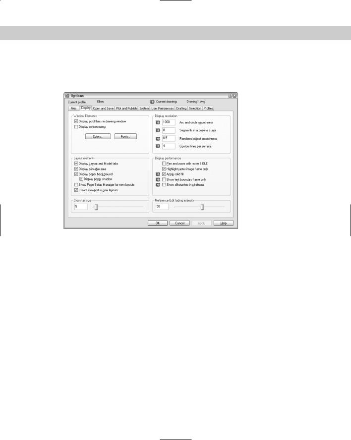
The Display tab, shown in Figure A-2, contains settings relating to the display you see on your screen.
Figure A-2: The Display tab of the Options dialog box.
The Windows Elements section determines whether you see scroll bars and the screen menu. (The screen menu is not available in AutoCAD LT.) You can also set the colors and fonts for the various screen elements. For example, by clicking Colors you can change the background color of the Model or Layout tabs.
The Layout Elements section creates display settings for paper space layouts. Most are checked by default. You can set the following items:
Uncheck Display Layout and Model Tabs to eliminate the tabs at the bottom of the drawing area. You might want to do this if you never use layouts.
Uncheck Display Printable Area to hide the dashed line that you usually see around a layout. The dashed line represents the margin of the paper and, therefore, shows you the printable area.
Uncheck Display Paper Background to avoid seeing the edge of the paper and the gray background. This setting makes a layout tab look very much like the model tab. If this item is checked, you can uncheck the Display Paper Shadow item to get rid of the shadow effect that makes the paper look like it’s slightly above the surface of the gray background.
Check Show Page Setup Manager for New Layouts to display the Page Setup Manager when you click a new layout tab.
Uncheck Create Viewport in New Layouts to display layouts with no viewport. This setting is useful if you always want to set up your own viewport configurations.

1086 Part VIII Appendixes
The Crosshair Size section sets the size of the crosshairs as a percentage of the entire screen. The default is 5. You can type a new number in the text box or drag the slider bar. To create crosshairs that cover the entire screen, use a setting of 100.
The Display Resolution section sets arc and circle smoothness (also settable using the VIEWRES command), the number of segments in a polyline curve (the SPLINESEGS system variable), rendered object smoothness (the FACETRES system variable), and contour lines per surface (the ISOLINES system variable). The last two items are not available in AutoCAD LT.
The Display Performance section offers settings that you can use to increase display speed. For example, several settings affect the way AutoCAD displays raster images. You can turn off FILLMODE, which applies solid fill in wide polylines, donuts, and hatched objects. AutoCAD LT only has the text boundary and solid fill items.
The Reference Edit fading intensity setting applies to objects during in-place reference editing. This setting affects how much objects that you are not editing are faded, compared to objects that you are editing. The default is 50 percent. For more information, see Chapter 19. This setting applies to AutoCAD only.
The Open and Save tab
The Open and Save tab, shown in Figure A-3, contains settings related to opening the program and files, as well as saving drawings.
Figure A-3: The Open and Save tab.
The File Save section sets the default drawing type and whether or not a thumbnail preview image is saved. You can see this preview when you want to open a new drawing and set the view to Preview. You can separately specify thumbnails for sheet sets.

Appendix A Installing and Configuring AutoCAD and AutoCAD LT 1087
Setting the Incremental Save percentage enables you to control when AutoCAD or AutoCAD LT saves the entire drawing as opposed to just your changes — an incremental save. The default is 50 percent, which avoids too many long full saves.
In the File Safety Precautions section, set the default time between automatic saves. The other settings in this section are:
Create Backup Copy with Each Save: By default, AutoCAD and AutoCAD LT create backup drawings whenever you save a drawing. Backup drawings have the same name as your drawing, but with an extension of BAK. Although you probably spend some time erasing these drawings, they can be very useful if a drawing becomes corrupted. You can always change their extension to DWG and open them as drawing files. However, you can turn off this feature. Unfortunately, you can’t control where the backup files are stored.
Full-Time CRC Validation: Check this item if data that you import is getting corrupted and you suspect a hardware problem. A cyclic redundancy check performs a validation during the importing process and can help you troubleshoot this problem.
Maintain a Log File: Keeps a log file that records the contents of the text window. Each time you work in AutoCAD, the new material is added to the end of the existing log file, so you should periodically edit or delete material from the log file. Use the Files tab to control the log file location.
File Extension for Temporary Files: Sets the filename extension for temporary files that are created while you’re working. By default, the extension for these files is AC$. Use the Files tab to control the temporary file location.
Use the Security Options section to set options for passwords and digital signatures. See Chapter 26 for details.
In the File Open section, you can set how many of the most recently used drawings you want to see at the bottom of the File menu. The default is nine in AutoCAD 2004, which is also the maximum setting. You can also choose whether or not you want to see the full path in the drawing listing.
In the External References (Xrefs) section, you can turn on and off demand loading of external references. When the Retain Changes to Xref Layers setting is checked (which it is by default), any changes you made to xref layer properties and states (such as freezing a layer) are saved. When you reopen the drawing containing the xref, these changes are retained. Finally, in AutoCAD only, you can set whether the current drawing can be edited in-place when someone else is referencing it. For more information, see Chapter 19.
In the ObjectARX Applications section (in AutoCAD only), you have settings related to ObjectARX applications and proxy graphics created by ObjectARX applications. ObjectARX is a programming interface for creating applications that work with AutoCAD. By default, the application is loaded when you either use one of the application’s commands or open a drawing containing a custom object created by the application. You can further restrict when the application is loaded to reduce demands on memory. In the Proxy Images for Custom Objects drop-down list, you can control how custom objects created by an ObjectARX application are displayed.
1088 Part VIII Appendixes
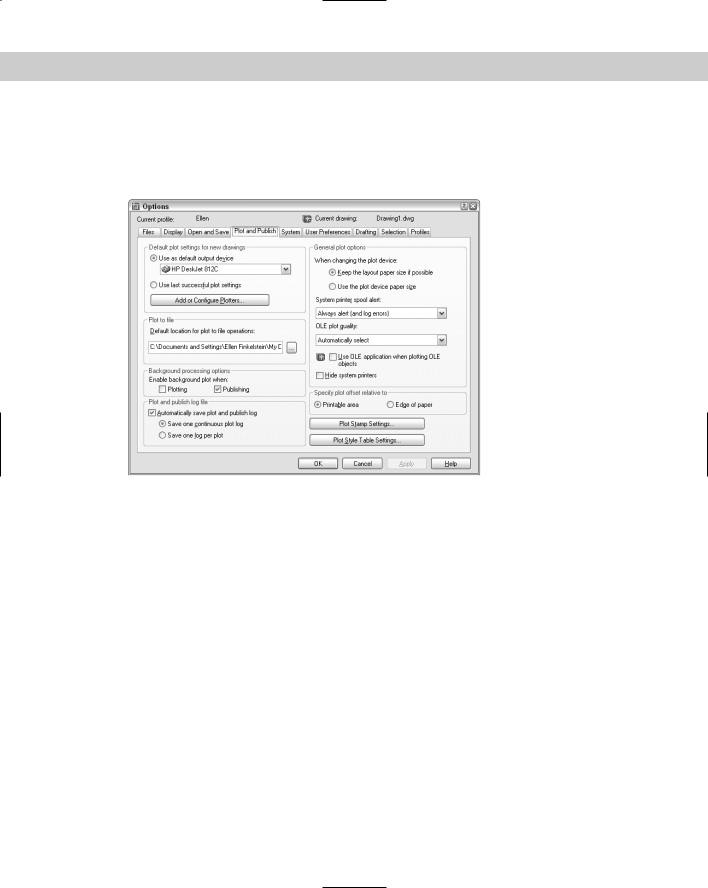
The Plot and Publish tab
The Plot and Publish tab, shown in Figure A-4, contains settings related to plotting and publishing, including plot style table settings. Later in this appendix, I explain how to configure a plotter.
Figure A-4: The Plot and Publish tab.
In the Default Plot Settings for New Drawings section, you set the default plotter/printer for new drawings and whether or not to use the same settings used the last time you plotted. As soon as you create plot settings for a drawing, those settings are saved with the drawing. Click Add or Configure Plotters for access to the Add-a-Plotter Wizard and existing plot configuration files. If you use a template, the plot settings in the template take precedence over the settings here.
The Plot to File section sets the default location for the file when you plot to a file. The Background Processing Options section determines whether plotting and publishing occur in the background (so that you can continue to work) or in the foreground. The Plot and Publish Log File section specifies whether to create a log file specifically for plotting and publishing operations.
In the General Plot Options section, you can choose whether to keep the paper size specified on the layout tab or use the plotter’s default paper size when you change plotters. You can also decide whether AutoCAD alerts you and creates an error log when the drawing is spooled through a system printer because of a port conflict.
In the same section, you can set a value for the quality of plotted OLE objects. You can choose from Line Art, Text, Graphics, Photograph, and High Quality Photograph. The default is Text. Check Use OLE Application When Plotting OLE Objects for the best quality when plotting OLE objects. Check Hide System Printers to repress the display of Windows system printers on the list of printers in the Plot and Page Setup dialog boxes so you can’t inadvertently print to your printer instead of to your plotter.
Appendix A Installing and Configuring AutoCAD and AutoCAD LT 1089
The Specify Plot Offset Relative To section determines how plot offsets (which you set in the Plot dialog box) work. Click the Plot Stamp Settings button to specify what you want to include if you add a plot stamp when plotting.
Click the Plot Style Table Settings button to decide whether to use color-dependent or named plot styles for new drawings and choose a default plot style table. You can also set default plot styles for layer 0 and objects. Click the Add or Edit Plot Style Tables button to go to the
Plot Styles folder where the plot style tables are stored. You can then double-click the Add- a-Plot Style Table Wizard to create a new table or open an existing table for editing. For more information on plotting and plot style tables, see Chapter 17.
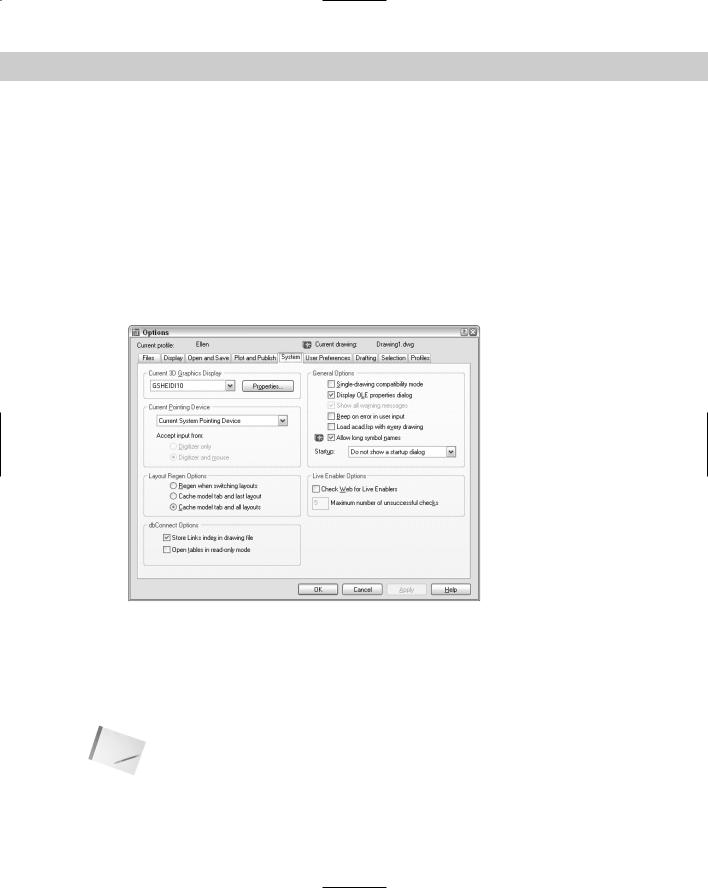
The System tab
The System tab contains a number of settings that affect how your computer works with AutoCAD or AutoCAD LT as well as some general settings. Figure A-5 shows the System tab.
Figure A-5: The System tab.
In the Current 3D Graphics Display section (AutoCAD only), you choose the display driver you want to use. The default is the HEIDI display driver that comes with AutoCAD. Click Properties to set the properties of the display driver.
In the Current Pointing Device section, you choose Wintab Compatible Digitizer ADI 4.2 if you have a digitizer. If you have a digitizing device, you can choose to accept input from only the digitizer or both the digitizer and the mouse.
Note |
If you’re installing a digitizer, follow the instructions provided by the digitizer manufacturer to |
|
configure Windows for the Wintab driver. The digitizer must be configured to work with |
|
Windows. |
1090 Part VIII Appendixes
In the Layout Regen Options section, you can choose to cache the model and layout tabs to avoid regenerations when you switch among the tabs.
In the dbConnect Options section (AutoCAD only), you can choose whether to store the index of database links in the drawing file to enhance performance during Link Select functions. You can also choose to open database tables in read-only mode — you won’t be able to edit them.
AutoCAD LT has a User Name section that contains your name and organization. This is derived from the information you provided at installation. You can change this name. The REVDATE command, which is available only in AutoCAD LT, uses this name to place a time stamp on your drawing.
In the General Options section, you can do the following:
Enable Single-Drawing Compatibility mode to disable the Multiple Document Interface so that AutoCAD can only open one drawing at a time. (Do this only if you’re having problems with existing AutoLISP programs and other customization.)
Turn off the display of the OLE properties dialog box when inserting OLE objects into AutoCAD drawings.
Bring back dialog boxes that have a Don’t Display This Warning Again check box (that you checked).
Tell AutoCAD to beep (or to remain silent) when it detects an invalid entry.
Determine whether AutoLISP loads acad.lsp into every drawing you open. By default, this box is not checked, meaning that only acaddoc.lsp is loaded into every drawing. (AutoCAD only.)
Disable long names for layers, dimension styles, blocks, linetypes, text styles, layouts, UCS names, views, and viewport configurations, for compatibility with prior releases.
Decide whether or not to display the Startup dialog box.
In the Live Enabler Options section, you can decide when you want to check for object enablers. Object enablers let the user display and use custom objects in drawings even when the application that created them is unavailable. For example, if you send a customer who is using Release 2000 a drawing with associative dimensions, that customer can use an object enabler to view those dimensions.
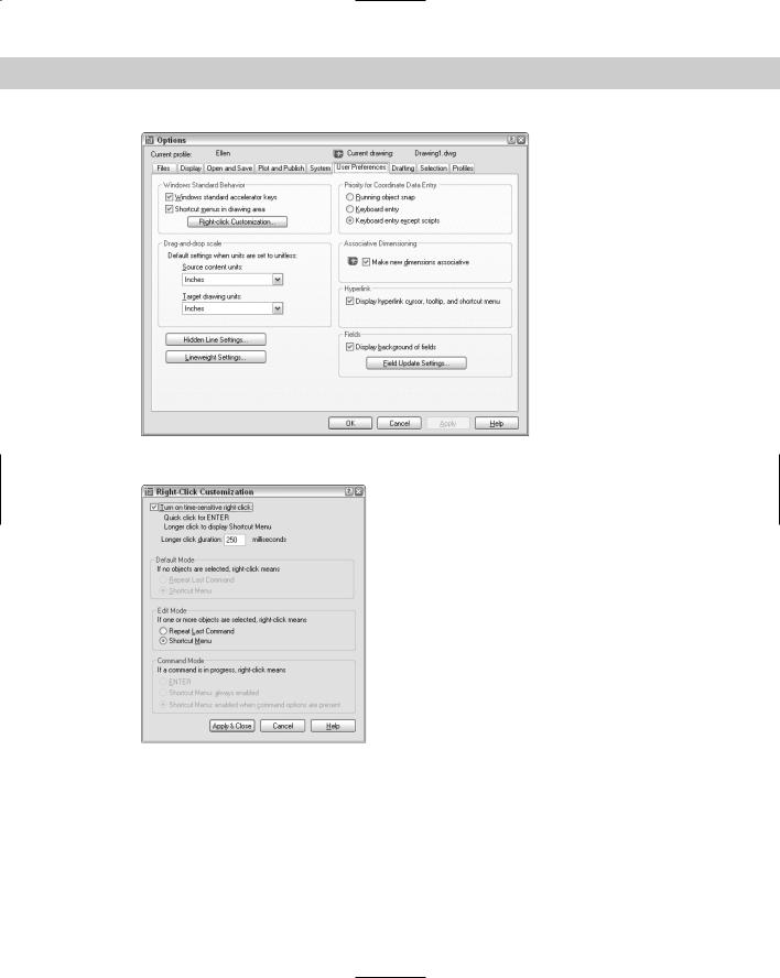
The User Preferences tab
The User Preferences tab, shown in Figure A-6, offers a variety of preference settings.
In the Windows Standard Behavior section, you can disable the Windows standard keyboard shortcuts such as Ctrl+C for the COPYCLIP command. When this item is disabled, Ctrl+C, for example, would revert to earlier-release AutoCAD usage and be equivalent to pressing the Esc key. You can also disable the shortcut menus that appear when you right-click in the drawing or command areas. Then you can right-click as an equivalent to pressing Enter.
Choose Right-Click Customization to open the dialog box shown in Figure A-7.
At the top of the Right-Click Customization dialog box, you can turn on time-sensitive right-click.
Appendix A Installing and Configuring AutoCAD and AutoCAD LT 1091
Figure A-6: The User Preferences tab.
Figure A-7: The Right-Click Customization dialog box.
With time-sensitive right-clicking, a quick right-click is equivalent to pressing Enter and will repeat the last command, for example, or end the LINE command (and other commands that require Enter to end). A longer right-click (hold your finger on the mouse slightly longer) opens the shortcut menu. You can specify the length of time required for the longer rightclick, which is 250 milliseconds by default.

1092 Part VIII Appendixes
In the Default Mode section, if you haven’t turned on time-sensitive right-clicking, you can choose Repeat Last Command to return to the Release 14 functioning of the right mouse button. In the Edit Mode section, you can choose Repeat Last Command to disable the shortcut menus only when one or more objects are selected but no command is in progress. When you do this, right-clicking automatically repeats the most recent command. In the Command Mode section, you have three choices if you haven’t turned on time-sensitive right-clicking:
Choose ENTER to disable the shortcut menus whenever a command is in progress. You then have to use the keyboard to choose command options.
Choose Shortcut Menu: Always Enabled to always have the shortcut menu available.
Choose Shortcut Menu: Enabled When Command Options Are Present as an in-between option — the shortcut menu is available when the command has options, but when the command has no options, right-clicking is like pressing Enter.
Click Apply & Close to close the Right-Click Customization dialog box and return to the User Preferences tab of the Options dialog box.
In the Drag-and-Drop Scale section of the User Preferences tab, you can specify default units for inserted objects (source contents units) and drawings (target drawing units) when dragging objects into a drawing from the DesignCenter or i-drop. When you don’t use the INSUNITS system variable (saved in your drawing), this setting determines the units to apply. You can choose anything from inches to parsecs!
Click the Hidden Line Settings button to specify how you want to show hidden lines. I discuss these settings in Chapter 21. Click the Lineweight Settings button to open the dialog box shown in Figure A-8. For more information on lineweights, see Chapter 11.
Figure A-8: The Lineweight Settings dialog box.
In the Lineweights list you can set the current lineweight. There are three standard lineweight styles: ByLayer, ByBlock, and Default. The Default value is 0.01 inches or 0.25 mm. All new layers have a default setting of Default. You can also set any specific width that you want. In the Units for Listing section, choose Millimeters or Inches. The default is Millimeters, probably because pen widths for pen plotters are traditionally defined in millimeters. Checking Display Lineweight is equivalent to clicking the LWT button on the status bar. In the Default drop-down list, you can change the default lineweight that new layers automatically use.
With the Adjust Display Scale bar you can control how lineweights are displayed on the Model tab. (Lineweights on a paper space layout are displayed in real-world units.) On the Model tab, lineweights are displayed in pixels using a proportion of pixel width to real-world unit value.
Depending on the resolution of your monitor, you may want to adjust the display scale to better see different lineweights.

Appendix A Installing and Configuring AutoCAD and AutoCAD LT 1093
Tip |
You can see the results of any display scale change immediately in the Lineweights list on the |
|
left of the dialog box. Scroll down to the bottom to see the difference for wider lineweights. |
|
Click Apply & Close to return to the User Preferences tab of the Options dialog box. |
|
In the Priority for Coordinate Data Entry section, you specify which gets priority — running |
|
object snaps or keyboard entry. By default, keyboard entry gets priority except in scripts — |
|
so you can use running object snaps when picking points on the screen but override them |
|
when you want to type in coordinates. |
|
In the Associative Dimensioning section, choose whether you want new dimensions to be |
|
associative, automatically adjusting as their associated objects change size. |
|
In the Hyperlink section, you can disable the hyperlink cursor (which appears when you pass |
|
the cursor over a hyperlink) and the hyperlink shortcut menu as well as the hyperlink tooltip |
|
that appears when you pass the cursor over a hyperlink. |
|
In the Fields section, you can turn on and off the gray border around fields. (The border doesn’t |
|
plot; it just indicates to you that the text is a field.) Click the Field Update Settings button to |
|
specify when fields are automatically updated. By default, they update when you open, save, |
|
plot, eTransmit, or regenerate a drawing. AutoCAD LT, which doesn’t have the field feature, |
|
only includes the ability to turn the border on and off. (AutoCAD LT can read fields created in |
|
AutoCAD drawings.) |
|
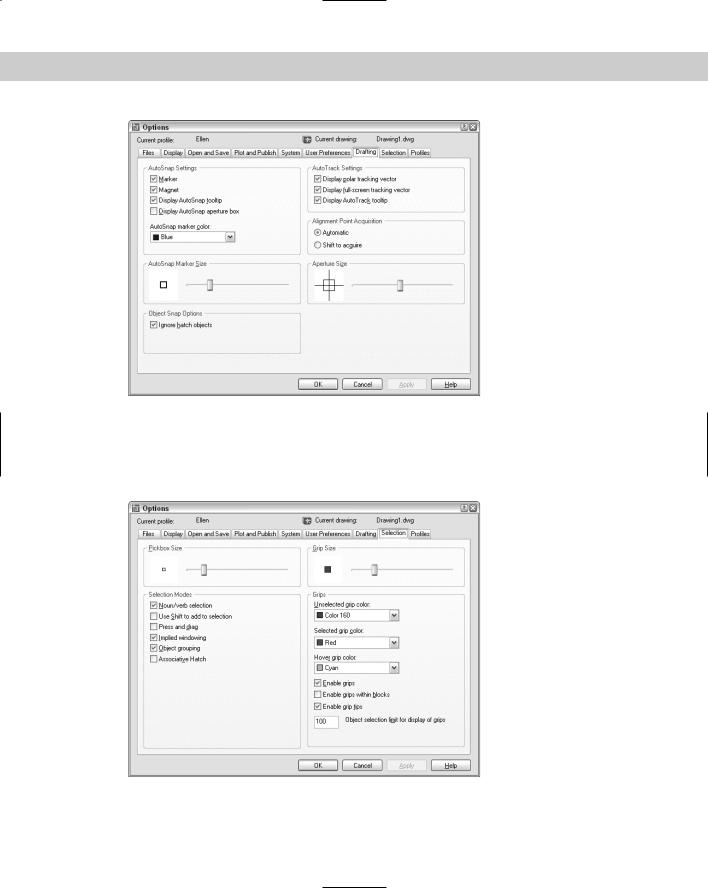
The Drafting tab |
|
The Drafting tab, shown in Figure A-9, includes AutoSnap and AutoTrack settings. |
|
In the AutoSnap Settings section, you can disable the marker (the shape you see for each |
|
object snap), the magnet (that draws the cursor to the object snap), and the tooltip (that |
|
says which object snap you’ve found). By default, the aperture is not displayed with AutoSnap |
|
markers because the combination can be confusing. You can also choose a color for the |
|
AutoSnap marker. By default, the marker is yellow, which shows up nicely against the default |
|
black screen. If you change the screen to white, you probably want to change the marker to a |
|
darker color. You can also change the marker size by dragging the control bar. |
|
In the Object Snap Options section, you can turn off the option to ignore hatch objects. By |
|
default, you cannot snap to hatch objects. If you want to snap to hatch objects, uncheck the |
|
check box. |
|
In the AutoTrack Settings section you control the visual elements for AutoTracking: |
Uncheck Display Polar Tracking Vector to disable the vector that appears when you move the cursor along a polar angle. You still see the tooltip.
Uncheck Display Full-Screen Tracking Vector to see only a localized vector when using object snap tracking — the vector appears between the acquired points instead of crossing the entire screen. (AutoCAD LT doesn’t offer this choice.)
Uncheck Display AutoTrack Tooltip to disable the tooltip that tells you which object snaps you’ve tracked.
In the Alignment Point Acquisition section (available only in AutoCAD), you can require pressing the Shift key to acquire points. You might do this if you find yourself acquiring points by accident, resulting in annoying tracking vectors.
Finally, you can set the aperture size for picking an object snap. However, the aperture box is off by default. (You can turn it on in the AutoSnap Settings section, as previously described.)
1094 Part VIII Appendixes
Figure A-9: The Drafting tab.
The Selection tab
The Selection tab contains settings that control how you select objects. This tab is shown in Figure A-10.
Figure A-10: The Selection tab.
Appendix A Installing and Configuring AutoCAD and AutoCAD LT 1095
Cross- |
The options in the Selection Modes and Pickbox Size sections, which customize object selec- |
Reference |
tion, are discussed in detail in Chapter 9. The options in the Grips and Grip Size sections are |
|
|
|
covered in Chapter 10. |
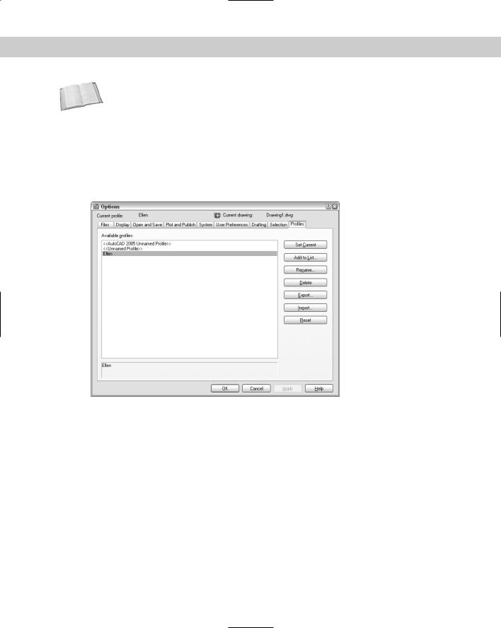
The Profiles tab
The Profiles tab, shown in Figure A-11, enables you to create user profiles. AutoCAD LT does not offer this feature (or the tab). A profile is a group of settings as set in the Options dialog box. If you share your system with someone else and you each want to store different settings, or if you want different settings for different projects, you can create a profile and make it current when you open AutoCAD.
Figure A-11: The Profiles tab with the default and one custom profile.
Whatever settings you create with the Options dialog box are automatically part of the default profile, which starts out with the exciting name of Unnamed Profile. Here’s how you create a new profile:
1.Click Add to List to open the Add Profile dialog box. Type in a profile name and description and click Apply & Close.
2.On the Profiles tab, click the new profile and choose Set Current.
3.Go through the other tabs and make the changes you want. Be sure to click Apply on each tab.
4.Click OK to close the Options dialog box.
To use the profile or another profile, choose Tools Options and click the Profiles tab. Choose the profile and click Set Current. Click OK to return to your drawing. You see the results immediately. Of course, some settings are not visible but make themselves evident in other ways — such as AutoCAD classic keyboard shortcuts and the creation of a log file.