

- •Foreword
- •Preface
- •Is This Book for You?
- •How This Book Is Organized
- •How to Use This Book
- •Doing the Exercises
- •Conventions Used in This Book
- •What the Icons Mean
- •About the CD-ROM
- •Other Information
- •Contacting the Author
- •Acknowledgments
- •Contents at a Glance
- •Contents
- •Getting Acquainted with AutoCAD and AutoCAD LT
- •Starting AutoCAD and AutoCAD LT
- •Creating a New Drawing
- •Using the AutoCAD and AutoCAD LT Interface
- •Creating Your First Drawing
- •Saving a Drawing
- •Summary
- •Creating a New Drawing from a Template
- •Working with Templates
- •Opening a Drawing with Default Settings
- •Opening an Existing Drawing
- •Using an Existing Drawing as a Prototype
- •Saving a Drawing Under a New Name
- •Summary
- •The Command Line
- •Command Techniques
- •Of Mice and Pucks
- •Getting Help
- •Summary
- •Typing Coordinates
- •Displaying Coordinates
- •Picking Coordinates on the Screen
- •Locating Points
- •Summary
- •Unit Types
- •Drawing Limits
- •Understanding Scales
- •Inserting a Title Block
- •Common Setup Options
- •The MVSETUP Command
- •Summary
- •Using the LINE Command
- •Drawing Rectangles
- •Drawing Polygons
- •Creating Construction Lines
- •Creating Rays
- •Summary
- •Drawing Circles
- •Drawing Arcs
- •Creating Ellipses and Elliptical Arcs
- •Making Donuts
- •Placing Points
- •Summary
- •Panning
- •The ZOOM Command
- •Aerial View
- •Named Views
- •Tiled Viewports
- •Snap Rotation
- •User Coordinate Systems
- •Isometric Drawing
- •Summary
- •Editing a Drawing
- •Selecting Objects
- •Summary
- •Copying and Moving Objects
- •Using Construction Commands
- •Creating a Revision Cloud
- •Hiding Objects with a Wipeout
- •Double-Clicking to Edit Objects
- •Grips
- •Editing with the Properties Palette
- •Selection Filters
- •Groups
- •Summary
- •Working with Layers
- •Changing Object Color, Linetype, and Lineweight
- •Working with Linetype Scales
- •Importing Layers and Linetypes from Other Drawings
- •Matching Properties
- •Summary
- •Drawing-Level Information
- •Object-Level Information
- •Measurement Commands
- •AutoCAD’s Calculator
- •Summary
- •Creating Single-Line Text
- •Understanding Text Styles
- •Creating Multiline Text
- •Creating Tables
- •Inserting Fields
- •Managing Text
- •Finding Text in Your Drawing
- •Checking Your Spelling
- •Summary
- •Working with Dimensions
- •Drawing Linear Dimensions
- •Drawing Aligned Dimensions
- •Creating Baseline and Continued Dimensions
- •Dimensioning Arcs and Circles
- •Dimensioning Angles
- •Creating Ordinate Dimensions
- •Drawing Leaders
- •Using Quick Dimension
- •Editing Dimensions
- •Summary
- •Understanding Dimension Styles
- •Defining a New Dimension Style
- •Changing Dimension Styles
- •Creating Geometric Tolerances
- •Summary
- •Creating and Editing Polylines
- •Drawing and Editing Splines
- •Creating Regions
- •Creating Boundaries
- •Creating Hatches
- •Creating and Editing Multilines
- •Creating Dlines
- •Using the SKETCH Command
- •Digitizing Drawings with the TABLET Command
- •Summary
- •Preparing a Drawing for Plotting or Printing
- •Creating a Layout in Paper Space
- •Working with Plot Styles
- •Plotting a Drawing
- •Summary
- •Combining Objects into Blocks
- •Inserting Blocks and Files into Drawings
- •Managing Blocks
- •Using Windows Features
- •Working with Attributes
- •Summary
- •Understanding External References
- •Editing an Xref within Your Drawing
- •Controlling Xref Display
- •Managing Xrefs
- •Summary
- •Preparing for Database Connectivity
- •Connecting to Your Database
- •Linking Data to Drawing Objects
- •Creating Labels
- •Querying with the Query Editor
- •Working with Query Files
- •Summary
- •Working with 3D Coordinates
- •Using Elevation and Thickness
- •Working with the User Coordinate System
- •Summary
- •Working with the Standard Viewpoints
- •Using DDVPOINT
- •Working with the Tripod and Compass
- •Getting a Quick Plan View
- •Shading Your Drawing
- •Using 3D Orbit
- •Using Tiled Viewports
- •Defining a Perspective View
- •Laying Out 3D Drawings
- •Summary
- •Drawing Surfaces with 3DFACE
- •Drawing Surfaces with PFACE
- •Creating Polygon Meshes with 3DMESH
- •Drawing Standard 3D Shapes
- •Drawing a Revolved Surface
- •Drawing an Extruded Surface
- •Drawing Ruled Surfaces
- •Drawing Edge Surfaces
- •Summary
- •Drawing Standard Shapes
- •Creating Extruded Solids
- •Drawing Revolved Solids
- •Creating Complex Solids
- •Sectioning and Slicing Solids
- •Using Editing Commands in 3D
- •Editing Solids
- •Listing Solid Properties
- •Summary
- •Understanding Rendering
- •Creating Lights
- •Creating Scenes
- •Working with Materials
- •Using Backgrounds
- •Doing the Final Render
- •Summary
- •Accessing Drawing Components with the DesignCenter
- •Accessing Drawing Content with Tool Palettes
- •Setting Standards for Drawings
- •Organizing Your Drawings
- •Working with Sheet Sets
- •Maintaining Security
- •Keeping Track of Referenced Files
- •Handling Errors and Crashes
- •Managing Drawings from Prior Releases
- •Summary
- •Importing and Exporting Other File Formats
- •Working with Raster Images
- •Pasting, Linking, and Embedding Objects
- •Summary
- •Sending Drawings
- •Opening Drawings from the Web
- •Creating Object Hyperlinks
- •Publishing Drawings
- •Summary
- •Working with Customizable Files
- •Creating Keyboard Shortcuts for Commands
- •Customizing Toolbars
- •Customizing Tool Palettes
- •Summary
- •Creating Macros with Script Files
- •Creating Slide Shows
- •Creating Slide Libraries
- •Summary
- •Creating Linetypes
- •Creating Hatch Patterns
- •Summary
- •Creating Shapes
- •Creating Fonts
- •Summary
- •Working with Menu Files
- •Customizing a Menu
- •Summary
- •Introducing Visual LISP
- •Getting Help in Visual LISP
- •Working with AutoLISP Expressions
- •Using AutoLISP on the Command Line
- •Creating AutoLISP Files
- •Summary
- •Creating Variables
- •Working with AutoCAD Commands
- •Working with Lists
- •Setting Conditions
- •Managing Drawing Objects
- •Getting Input from the User
- •Putting on the Finishing Touches
- •Summary
- •Understanding Local and Global Variables
- •Working with Visual LISP ActiveX Functions
- •Debugging Code
- •Summary
- •Starting to Work with VBA
- •Writing VBA Code
- •Getting User Input
- •Creating Dialog Boxes
- •Modifying Objects
- •Debugging and Trapping Errors
- •Moving to Advanced Programming
- •A Final Word
- •Installing AutoCAD and AutoCAD LT
- •Configuring AutoCAD
- •Starting AutoCAD Your Way
- •Configuring a Plotter
- •System Requirements
- •Using the CD with Microsoft Windows
- •What’s on the CD
- •Troubleshooting
- •Index

418 Part II Drawing in Two Dimensions
3.Choose Modify Object Polyline to start the PEDIT command. Select the polyline at 1 in Figure 16-4.
4.At the Enter an option [Close/Join/Width/Edit vertex/Fit/Spline/Decurve/
Ltype gen/Undo]: prompt, right-click and choose Width. At the Specify new width for all segments: prompt, type .5 .
5.Type e to choose the Edit vertex option. At the Enter a vertex editing option
[Next/Previous/Break/Insert/Move/Regen/Straighten/Tangent/Width/eXit] <N>: prompt, type n several times until the X mark is at 1 in Figure 16-4. (There are many vertices — it’s not important that you find the exact one.)
6.Type m to move the vertex. At the Specify new location for marked vertex: prompt, pick a point slightly above the existing vertex. Then, type x to exit the Edit vertex submenu.
7.At the main PEDIT prompt, type s . PEDIT smoothes out the polyline.
8.Press Enter to exit the PEDIT command.
9.Save your drawing.
Drawing and Editing Splines
The SPLINE command draws a NURBS, which stands for nonuniform rational B-spline. Not to get too technical, a spline is a smooth curve that is defined by a series of points. The SPLINE command provides a more precise representation of a spline than the Spline option of the PLINE command. By default, the curve passes through each point you define. Figure 16-5 shows a beanbag chair created with two splines.
Figure 16-5: A beanbag chair created with two splines.
Creating splines
To create a spline, choose Spline from the Draw menu. The command responds with the Specify first point or [Object]: prompt. Use the Object option to convert a
polyline that you’ve created with PEDIT’s Spline option into a true spline. (It won’t look any different, but its internal definition changes.) Otherwise, specify the first point for the spline.
If you choose a point, the command displays the Specify next point: prompt so that you can pick a second point. After you do so, you see the Specify next point or [Close/Fit tolerance] <start tangent>: prompt. Use these options as follows:
Chapter 16 Drawing Complex Objects 419
On the
CD-ROM
Close: Closes the spline by connecting the last point with the first in a continuous (tangent) curve. The prompt asks for a tangent direction. You can specify a direction by picking a point (watch the spline image change as you move the cursor) or pressing Enter to accept the default tangent direction.
Fit Tolerance: Specifies how closely the spline comes to the points you pick. The default, 0, creates a spline that passes through each point. If you want the curve to have a latitude of 0.5 units from the points, set the tolerance to 0.5.
Specify next point: The default is to continue entering points. Press Enter to end point selection.
Start tangent: When you press Enter to complete point selection, you’re prompted for start and ending tangent directions. You can press Enter at both prompts to accept the default tangents based on the curve’s current shape. You can see the effect of other tangent points by moving the cursor and watching the image change.
The drawing used in the following Step-by-Step exercise on drawing splines, ab16-c.dwg, is in the Drawings folder on the CD-ROM.
STEP-BY-STEP: Drawing Splines
1.Open ab16-c.dwg from your CD-ROM.
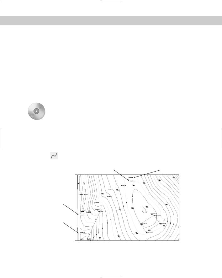
2.Save the file as ab16-03.dwg in your AutoCAD Bible folder. This is a topographical site map, shown in Figure 16-6. OSNAP should be on. Set a running object snap for insertion.
3.Use Zoom Window to zoom in on the area near the start of the north edge of the drive. Choose Spline from the Draw toolbar.
Start of south edge of drive |
Start of north edge of drive |
End of north edge of drive
End of south edge of drive
Figure 16-6: A topographical site map. You can complete the gravel road based on surveyor’s data.
420 Part II Drawing in Two Dimensions
On the
CD-ROM
4.At the Specify first point or [Object]: prompt, use the Insert object snap to pick the cross at the start of the north edge of the drive, as shown in Figure 16-6. Continue to pick the crosses marked N-EDGE-DR. Choose Pan from the Standard toolbar to do a real-time pan when you reach the edge of the display. Press Esc. Continue picking points until you get to the end of the north edge of the drive, as shown in Figure 16-6. Press Enter to end point selection.
5. At the Specify start tangent: and Specify end tangent: prompts, press Enter.
6.Start the SPLINE command again and pick points for the south edge of the drive, from the start of the south edge of the drive to the end, as shown in Figure 16-6. Pan as necessary. Again, press Enter to accept the default directions for the start and end tangents.
7.If you want, choose Zoom Previous on the Standard toolbar several times until you see the original view of the drawing. Save your drawing.
GeomCurves.lsp is a routine that creates various kinds of geometrical curves, such as spirals and parabolas. You can find it in the \Software\Chap16\GeomCurves folder.
Editing splines
Like polylines, splines have their own editing command. To understand how to edit splines, you need to understand how your drawing stores them.
When you pick points to create the spline, AutoCAD stores these points as fit points (or data points). If the tolerance is zero, the curve lies on these fit points. When you select a spline at the command line, grips appear at these fit points. However, when you use the SPLINEDIT command, to see the fit points as grips, you must choose the Fit Data option first. Only then can you edit the fit points.
AutoCAD and AutoCAD LT calculate control points based on the fit points. The spline is then calculated based on the control points, not the fit points. Most of the control points are not on the spline. When you use SPLINEDIT to edit a spline, and use the Move vertex option described later, you see the control points displayed as grips, and you can move the control points.
Figure 16-7 shows a spline created using point objects as the fit points — these were the points picked when creating the spline. Note that the spline passes through each fit point.
Figure 16-7: The point objects were used as the pick points. These are the fit points of the spline.
Figure 16-8 shows the same spline as in Figure 16-7, where it appears when selected with no command active. Notice that the grips are exactly on the fit points.
Because the spline is calculated based on the control points, the fit points are not necessary to generate the spline. In fact, if you use the Move vertex or Refine options to move or edit a control point, only the control points are needed to generate the spline and the fit point information is discarded so you can no longer edit it. The Fit Data option also disappears from the prompt. You can edit the fit points using grips.
Chapter 16 Drawing Complex Objects 421
Figure 16-8: When you select a spline with no command active, you see grips on the fit points.
To edit a spline, choose Modify Object Spline to start the SPLINEDIT command. After you select the spline, the command responds with the Enter an option [Fit data/Close/ Move vertex/Refine/rEverse/Undo]: prompt. Here’s how to use these options:
Fit Data: Fit data means the points you’ve chosen, their tolerance, and the tangents. Use this option to edit fit data. This option has its own list of suboptions that are explained after this list.
Close/Open: If the spline is open, this option closes it by adding a continuous (tangent) curve from the last point to the start point. If the spline is closed, this option appears as Open. If the spline was originally closed, the Open option removes the connection between the last and first points, although the spline looks the same. If the spline was originally open and you closed it, when you use the Open option, this option erases the curve that it added when you closed it.
Move Vertex: This works like the Edit vertex option of PEDIT, except that this option displays the points as grips and highlights them. You can use Next and Previous suboptions, select any point to move, and pick a new location for the highlighted vertex.
Refine: Enables you to refine the spline in three ways:
•Add control points: This doesn’t change the shape of the spline but adjusts nearby control points slightly.
•Elevate the order of the spline: This adds control points throughout the spline (but once you go up, you can’t go down).
•Change the weight of any control point: This is like the gravity the control point exerts on the spline. Watch the spline inch toward the control point as you increase its weight.
rEverse: Reverses the direction of the spline so that the start point becomes the endpoint, and vice versa.
Undo: Undoes the most recent edit operation.
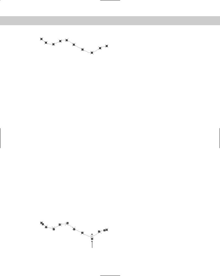
When you use the SPLINEDIT command and select a spline, you see control points, not fit points. In Figure 16-9, the grips indicate the control points.
Fit point |
Figure 16-9: When you choose the |
|
|
|
SPLINEDIT command and select a spline, |
|
|
the grips indicate the control points, which |
|
|
are not generally on the spline. |
|
|
|
Control point