828 Part V Organizing and Managing Drawings
6.On the Sheet List tab, double-click the External Sections sheet to open it. Make viewport the current layer. Click the Resource Drawings tab. Right-click the Section 2 view and choose Place on Sheet. In the drawing area, right-click and choose 1/16"=1' and pick a point for the view.
7.Click the View List tab to see the views that you’ve placed. To number these views, right-click each view and choose Rename and Renumber. Because you’re only placing one view on a sheet, number each view 1 and click OK.
8.To place a callout bubble on the basement floor plan that references the Exterior Section sheet, click the tab on the Windows taskbar for the basement floor plan to display that drawing. Click the View List tab. This tab now lists the views that you just placed.
Right-click the Section 2 view (the one that you’re pointing to) and choose Place Callout Blocks callout bubble-left arrow. At the prompt, pick 1 in Figure 26-27. The fields in the callout block show the correct view and sheet numbers.
9.If you have a printer or plotter available, click the Sheet List tab. Select the
Basement Floor Plan and Exterior Sections sheets. Right-click the sheet-set name and choose Publish Publish to Plotter. Click the Sheet Selections button and choose Create. Name the selection basement-exterior sections and click OK.
10. Choose Publish Publish to Plotter. The two sheets are plotted.
11.To create a table that lists all the sheets, first create a new sheet. On the Sheet List tab, right-click the sheet-set name and choose New Sheet. Number it 0 and name it Cover Sheet. Delete the 0 from the filename and click OK.
12.Double-click the new sheet’s name to open it.
13.Right-click the sheet-set name and choose Insert Sheet List Table. From the Table Style Name drop-down list, choose Sheet Set List. (This table style was saved with the template.) The Show Subheader check box should be checked. In the Title Text box, type AB26-f Sheets. For the column settings, set up the following columns. If necessary, click Add to add a column.
Sheet Number |
Sheet No. |
Sheet Title |
Sheet Name |
Drawing Author |
By |
14.Click OK twice to return to your drawing. Pick an insertion point for the table.
15.Save and close any open drawings.
Maintaining Security
In these days of collaboration and interconnectivity, maintaining security is an important issue. Two features to help you keep your designs secure.
Password protection
Password protection ensures that unauthorized people don’t open your drawings. You create a password when you save a drawing.
Chapter 26 Keeping Control of Your Drawings |
829 |
AutoCAD LT does not offer password protection.
To create a password for a drawing, type securityoptions on the command line. The Security Options dialog box opens.
Caution |
Before adding a password, save the drawing under another name or in a different location so |
|
that you have a copy. If you lose or forget the password, you won’t be able to open the draw- |
|
ing. You can turn password protection off for network installations of AutoCAD. |
To password-protect a drawing:
1.Type a password in the text box.
2.If you also want to encrypt drawing properties that identify the drawing, such as the title, author, subject, and keywords, check the Encrypt Drawing Properties check box.
3.Click OK.
4.The Confirm Password dialog box appears. Retype the password.
5.Click OK.
You can also change or remove a password:
1.Open the Security Options dialog box.
2.Type a new password or delete the current password. Click OK.
3.If you type a new password, reconfirm the password and click OK.
The dialog box displays the current encryption type. To specify a different encryption, click Advanced Options. Choose a new encryption type from the list and a key length, and then click OK.
When a password-protected drawing is opened, the Password dialog box appears. To open the drawing, type the password and click OK.
Digital signatures
A digital signature uses software that confirms who signed the drawing, that it has not been changed, and non-repudiation (so that signers cannot claim they never signed the drawing). To use a digital signature, you need to purchase a digital ID. You can use digital IDs in both AutoCAD and AutoCAD LT.
Generally, you would use a digital signature when you send a drawing to someone else. That person can then verify that the drawing is from you and has not been changed. If the person sends the drawing back to you, you can verify that the person has not changed the drawing, because changing the drawing invalidates the digital signature.
Note |
The Digital Signatures tab of the Security Options dialog box contains a link to VeriSign, a com- |
|
pany that sells digital certificates. You can obtain a 60-day free trial or purchase a digital ID at |
|
one of several levels of security. If you don’t have a digital signature and want to use VeriSign, |
|
choose Tools Options and click the Open and Save tab. Click Security Options and then the |
|
Digital Signatures tab. A message displays explaining that you don’t have a valid digital ID. Click |
|
Get a Digital ID to go to VeriSign’s Web site. Follow the instructions at the site to sign up for and |
|
install the digital ID. Although the initial Web page is specific to Autodesk, the final instructions |
|
assume that you want to use the digital ID for e-mail. You can ignore those instructions. |
830 Part V Organizing and Managing Drawings
To attach a digital signature to a drawing, follow these steps:
1.Choose Tools Options and click the Open and Save tab. Click Security Options and then the Digital Signatures tab.
2.Choose a digital signature and check the Attach Digital Signature after Saving Drawing check box.
3.To place a time stamp on the drawing, choose one of the options from the Get Time Stamp From drop-down list.
4.To add a comment (that appears when the drawing is opened), type the text in the Comment text box.
5.Click OK.
When a digitally signed drawing is opened, the Digital Signature Contents dialog box appears, verifying the digital signature and the fact that the drawing has not been changed since it was signed. Click Close to close the dialog box.
Note that making any changes to the drawing invalidates the digital ID. If you make changes or try to save a drawing with an attached digital signature, a message appears asking you if you want to continue. When you re-open the drawing, the Digital Signature Contents dialog box appears, displaying the fact that the digital signature is invalid.
A drawing with a valid digital signature has a checkmark attached to its icon in Windows Explorer. The drawing itself also sports an icon in the status bar, as shown in Figure 26-28.
Figure 26-28: A drawing with a valid digital signature, shown in Windows Explorer and on its status bar.
Note Users who don’t have the Digital Signature feature can download the Digital Signature Verifier, a free application to verify digital signatures on signed drawings. The Digital Signature Verifier is available from the Autodesk Web site at http://usa.autodesk.com/adsk/ item/0,,877495-123112-587113,00.html. (You can also go to www.autodesk.com and do a search on Digital Signature Verifier.)
Keeping Track of Referenced Files
A drawing references several types of outside files, and you often need to keep track of these files, especially when you send a drawing to someone else or move it to another computer. Also, the referenced files may be moved, even if the drawing stays in the same place. Without these outside files, the drawing is not complete.
AutoCAD LT does not include the Reference Manager.
Chapter 26 Keeping Control of Your Drawings |
831 |
Outside files include:
Other drawings (xrefs)
Text fonts
Images
Plot configurations
The Reference Manager not only lists referenced files but enables you to change saved reference paths so that the drawing can find the needed files. You don’t even need to open the AutoCAD drawing, because the Reference Manager is a stand-alone application.
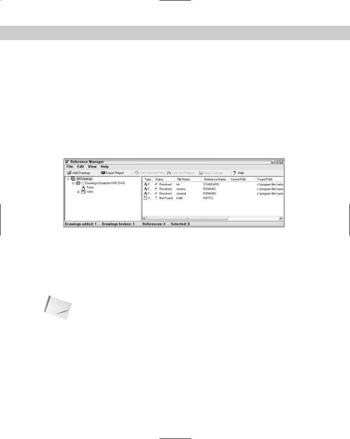
To open the Reference Manager, choose Start Programs Autodesk AutoCAD 2005 Reference Manager, shown in Figure 26-29.
Figure 26-29: The Reference Manager.
To add drawings to the Reference Manager, click Add Drawings and select the drawings. If a drawing has xrefs, you see a message asking if you want to add the xrefs. To add them, click Yes.
The left pane of the Reference Manager contains a tree view of the drawings you’ve added and external references, if any. The right pane is a Reference list and displays the specific external files associated with the added files. You can choose View Options in the Reference Manager to customize how the Reference Manager displays files.
Note |
Reference Manager does not find text fonts not used in a text style, TrueType fonts not saved in |
|
the Windows Fonts folder, OLE links, hyperlinks, database file links, PMP files, and external |
|
references to URLs on the Web. |
To modify the path of an external reference so that a drawing can find it, follow these steps:
1.Close any drawings or files that you might need to access.
2.Choose a drawing in the left pane.
3.Right-click the external reference in the Reference list that you want to change and choose Edit Selected Paths. (You can also choose Edit Selected Paths from the Reference Manager’s toolbar.)