

- •Foreword
- •Preface
- •Is This Book for You?
- •How This Book Is Organized
- •How to Use This Book
- •Doing the Exercises
- •Conventions Used in This Book
- •What the Icons Mean
- •About the CD-ROM
- •Other Information
- •Contacting the Author
- •Acknowledgments
- •Contents at a Glance
- •Contents
- •Getting Acquainted with AutoCAD and AutoCAD LT
- •Starting AutoCAD and AutoCAD LT
- •Creating a New Drawing
- •Using the AutoCAD and AutoCAD LT Interface
- •Creating Your First Drawing
- •Saving a Drawing
- •Summary
- •Creating a New Drawing from a Template
- •Working with Templates
- •Opening a Drawing with Default Settings
- •Opening an Existing Drawing
- •Using an Existing Drawing as a Prototype
- •Saving a Drawing Under a New Name
- •Summary
- •The Command Line
- •Command Techniques
- •Of Mice and Pucks
- •Getting Help
- •Summary
- •Typing Coordinates
- •Displaying Coordinates
- •Picking Coordinates on the Screen
- •Locating Points
- •Summary
- •Unit Types
- •Drawing Limits
- •Understanding Scales
- •Inserting a Title Block
- •Common Setup Options
- •The MVSETUP Command
- •Summary
- •Using the LINE Command
- •Drawing Rectangles
- •Drawing Polygons
- •Creating Construction Lines
- •Creating Rays
- •Summary
- •Drawing Circles
- •Drawing Arcs
- •Creating Ellipses and Elliptical Arcs
- •Making Donuts
- •Placing Points
- •Summary
- •Panning
- •The ZOOM Command
- •Aerial View
- •Named Views
- •Tiled Viewports
- •Snap Rotation
- •User Coordinate Systems
- •Isometric Drawing
- •Summary
- •Editing a Drawing
- •Selecting Objects
- •Summary
- •Copying and Moving Objects
- •Using Construction Commands
- •Creating a Revision Cloud
- •Hiding Objects with a Wipeout
- •Double-Clicking to Edit Objects
- •Grips
- •Editing with the Properties Palette
- •Selection Filters
- •Groups
- •Summary
- •Working with Layers
- •Changing Object Color, Linetype, and Lineweight
- •Working with Linetype Scales
- •Importing Layers and Linetypes from Other Drawings
- •Matching Properties
- •Summary
- •Drawing-Level Information
- •Object-Level Information
- •Measurement Commands
- •AutoCAD’s Calculator
- •Summary
- •Creating Single-Line Text
- •Understanding Text Styles
- •Creating Multiline Text
- •Creating Tables
- •Inserting Fields
- •Managing Text
- •Finding Text in Your Drawing
- •Checking Your Spelling
- •Summary
- •Working with Dimensions
- •Drawing Linear Dimensions
- •Drawing Aligned Dimensions
- •Creating Baseline and Continued Dimensions
- •Dimensioning Arcs and Circles
- •Dimensioning Angles
- •Creating Ordinate Dimensions
- •Drawing Leaders
- •Using Quick Dimension
- •Editing Dimensions
- •Summary
- •Understanding Dimension Styles
- •Defining a New Dimension Style
- •Changing Dimension Styles
- •Creating Geometric Tolerances
- •Summary
- •Creating and Editing Polylines
- •Drawing and Editing Splines
- •Creating Regions
- •Creating Boundaries
- •Creating Hatches
- •Creating and Editing Multilines
- •Creating Dlines
- •Using the SKETCH Command
- •Digitizing Drawings with the TABLET Command
- •Summary
- •Preparing a Drawing for Plotting or Printing
- •Creating a Layout in Paper Space
- •Working with Plot Styles
- •Plotting a Drawing
- •Summary
- •Combining Objects into Blocks
- •Inserting Blocks and Files into Drawings
- •Managing Blocks
- •Using Windows Features
- •Working with Attributes
- •Summary
- •Understanding External References
- •Editing an Xref within Your Drawing
- •Controlling Xref Display
- •Managing Xrefs
- •Summary
- •Preparing for Database Connectivity
- •Connecting to Your Database
- •Linking Data to Drawing Objects
- •Creating Labels
- •Querying with the Query Editor
- •Working with Query Files
- •Summary
- •Working with 3D Coordinates
- •Using Elevation and Thickness
- •Working with the User Coordinate System
- •Summary
- •Working with the Standard Viewpoints
- •Using DDVPOINT
- •Working with the Tripod and Compass
- •Getting a Quick Plan View
- •Shading Your Drawing
- •Using 3D Orbit
- •Using Tiled Viewports
- •Defining a Perspective View
- •Laying Out 3D Drawings
- •Summary
- •Drawing Surfaces with 3DFACE
- •Drawing Surfaces with PFACE
- •Creating Polygon Meshes with 3DMESH
- •Drawing Standard 3D Shapes
- •Drawing a Revolved Surface
- •Drawing an Extruded Surface
- •Drawing Ruled Surfaces
- •Drawing Edge Surfaces
- •Summary
- •Drawing Standard Shapes
- •Creating Extruded Solids
- •Drawing Revolved Solids
- •Creating Complex Solids
- •Sectioning and Slicing Solids
- •Using Editing Commands in 3D
- •Editing Solids
- •Listing Solid Properties
- •Summary
- •Understanding Rendering
- •Creating Lights
- •Creating Scenes
- •Working with Materials
- •Using Backgrounds
- •Doing the Final Render
- •Summary
- •Accessing Drawing Components with the DesignCenter
- •Accessing Drawing Content with Tool Palettes
- •Setting Standards for Drawings
- •Organizing Your Drawings
- •Working with Sheet Sets
- •Maintaining Security
- •Keeping Track of Referenced Files
- •Handling Errors and Crashes
- •Managing Drawings from Prior Releases
- •Summary
- •Importing and Exporting Other File Formats
- •Working with Raster Images
- •Pasting, Linking, and Embedding Objects
- •Summary
- •Sending Drawings
- •Opening Drawings from the Web
- •Creating Object Hyperlinks
- •Publishing Drawings
- •Summary
- •Working with Customizable Files
- •Creating Keyboard Shortcuts for Commands
- •Customizing Toolbars
- •Customizing Tool Palettes
- •Summary
- •Creating Macros with Script Files
- •Creating Slide Shows
- •Creating Slide Libraries
- •Summary
- •Creating Linetypes
- •Creating Hatch Patterns
- •Summary
- •Creating Shapes
- •Creating Fonts
- •Summary
- •Working with Menu Files
- •Customizing a Menu
- •Summary
- •Introducing Visual LISP
- •Getting Help in Visual LISP
- •Working with AutoLISP Expressions
- •Using AutoLISP on the Command Line
- •Creating AutoLISP Files
- •Summary
- •Creating Variables
- •Working with AutoCAD Commands
- •Working with Lists
- •Setting Conditions
- •Managing Drawing Objects
- •Getting Input from the User
- •Putting on the Finishing Touches
- •Summary
- •Understanding Local and Global Variables
- •Working with Visual LISP ActiveX Functions
- •Debugging Code
- •Summary
- •Starting to Work with VBA
- •Writing VBA Code
- •Getting User Input
- •Creating Dialog Boxes
- •Modifying Objects
- •Debugging and Trapping Errors
- •Moving to Advanced Programming
- •A Final Word
- •Installing AutoCAD and AutoCAD LT
- •Configuring AutoCAD
- •Starting AutoCAD Your Way
- •Configuring a Plotter
- •System Requirements
- •Using the CD with Microsoft Windows
- •What’s on the CD
- •Troubleshooting
- •Index
334 Part II Drawing in Two Dimensions
Table 13-3 (continued)
Command |
Menu |
Description |
|
|
|
ARCTEXT |
Express Text Arc-Aligned |
Aligns text along an arc. |
|
Text |
|
TORIENT |
Express Text Rotate Text |
Rotates multiple text, Mtext, and attribute definitions |
|
|
to a specified angle without moving them or aligns |
|
|
them so that they’re horizontal or right-side up for |
|
|
easy reading. |
TCIRCLE |
Express Text Enclose Text |
Encloses selected Text or Mtext inside a circle, a slot |
|
with Object |
(a rectangle, but with arcs at each end), or a rectangle. |
TCOUNT |
Express Text Automatic |
Numbers lines of text by adding a prefix or suffix, |
|
Text Numbering |
or by overwriting the text. |
TCASE |
Express Text Change |
Offers the following ways to change the case of text: |
|
Text Case |
uppercase, lowercase, sentence case, title case, and |
|
|
toggle case. |
|
|
|
Finding Text in Your Drawing
In a large, complex drawing with a lot of text, you may have difficulty finding specific text that you need to edit. The FIND command lets you find and replace text anywhere in your drawing — not only single-line text and multiline text but also text in block attributes, dimensions, and hyperlinks.
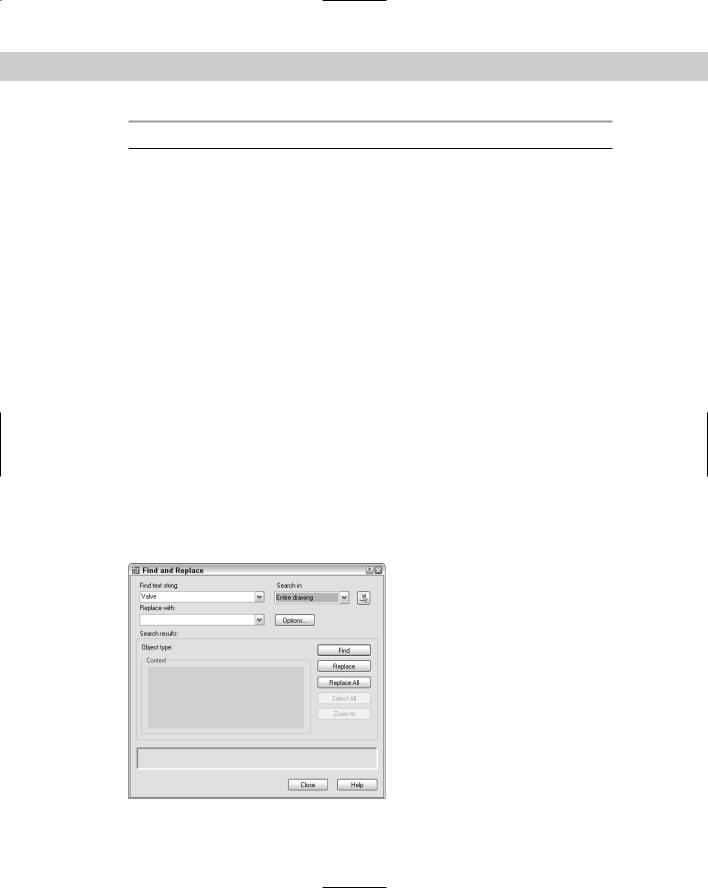
To use the FIND command, choose Edit Find to open the Find and Replace dialog box, as shown in Figure 13-32.
Figure 13-32: The Find and Replace dialog box finds text anywhere in your drawing.

Chapter 13 Creating Text 335
Here’s how to use the Find and Replace dialog box:
1.Type the text you want to find in the Find text string text box. Use the drop-down list to choose recently used text strings.
2.If you want to replace the text you find with new text, type it in the Replace With text box. This box also includes a drop-down list of recently used text strings.
3.If you want to limit or expand the scope of your search, use the Search In drop-down box. If you selected objects before starting the FIND command, this drop-down list displays Current Selection. You can choose Entire Drawing from this list. You can also click the Select Objects button to return to your drawing and select objects. The FIND command then limits its search to selected objects.
4.Choose Options to specify the type of text FIND will search. By default it searches all types of text. The command can find text in fields as well. You can also choose the Match Case and Find Whole Words Only options.
5.Click Find (Next) to find the next instance of the text string. The dialog box displays the text in the context of the text around it.
6.Click Replace to replace the text string with the replacement text. Click Replace All to replace all instances of the text string with the replacement text.
7.If the Search In drop-down list is set to Current Selection, you can click Select All to return to your drawing with all instances of the text string you’ve searched for selected. The prompt on the command line tells you how many objects it has selected. You can use this feature to delete all these objects, for example. Also, because the objects have grips, it is easy to locate them in your drawing — this is useful for a drawing large enough so that you can’t read the text when you have the entire drawing displayed on your screen.
8.Use the Zoom To button to zoom in to a selection that the FIND command has found. You can then edit the text. As with the Select All button, this feature is useful for large drawings where the text is not legible unless you zoom in.
9.After you’re finished, click Close to close the dialog box.
Checking Your Spelling
If you take pride in the accuracy of your drawings, you might as well make sure that the text is spelled correctly. Use the SPELL command to check your spelling. The spelling checker acts just like the one in your word processor.
Choose Tools Spelling and select some text objects to open the Check Spelling dialog box, as shown in Figure 13-33. You can type all to check the spelling for the entire drawing.
Note Spell checking also checks text inside blocks. See Chapter 18 for the full explanation of blocks.

336 Part II Drawing in Two Dimensions
Figure 13-33: The Check Spelling dialog box.
You have the following options:
Ignore: Choose Ignore to ignore the current instance of this word only.
Ignore All: Choose Ignore All to ignore all instances of this word.
Change: Select the suggested word you want and choose Change to change the current instance of the word to one of the suggested words.
Change All: Select the suggested word you want and choose Change All to change all instances of the word to one of the suggested words.
Add: Choose Add to add the word to the dictionary. The word will not appear again as misspelled.
Lookup: Use this if you type a word in the Suggestion text box and want to check its spelling. You then see a list of words similar to the word in the Suggestion text box.
The command automatically moves from word to word until you see the message Spelling Check Complete.
|
Customizing the spelling dictionary |
|
You can change the main and custom spelling dictionaries. To change the spelling dictionar- |
|
ies, choose Change Dictionaries from the Check Spelling dialog box to open the Change |
|
Dictionaries dialog box, as shown in Figure 13-34. |
Tip |
Strangely enough, if you don’t have any misspelled words in your drawing, you cannot open |
|
the Check Spelling dialog box. You simply get the Spelling Check Complete message. The |
|
trick is to insert a misspelled word and then use the SPELL command. You can erase or cor- |
|
rect the word afterward. |
|
The main dictionary is not customizable. You can choose from various languages depending |
|
on your version of AutoCAD or AutoCAD LT. For example, my list lets me choose from |
|
American English, British English (ise), British English (ize), French with unaccented capitals, |
|
and French with accented capitals. |
Chapter 13 Creating Text 337
Figure 13-34: The Change Dictionaries dialog box.
|
The custom spelling dictionary is the dictionary you add to when you click Add in the Check |
|
Spelling dialog box. It is a simple text file that includes words that you have added during |
|
spelling checks, as well as a list of drawing-related words that come with the file. To see these |
|
words, scroll down the list in the Custom Dictionary Words section of the Change |
|
Dictionaries dialog box. |
|
You can add words to the custom dictionary by typing them in the Custom Dictionary Words |
|
text box and clicking Add. This feature lets you add a number of words at one time. |
Tip |
Another way to edit the custom dictionary is to open the file directly with a text editor. The |
|
custom dictionary is called sample.cus. To find sample.cus, choose Tools Options and |
|
click the File tab. Double-click Text Editor, Dictionary, and Font File Names. Double-click |
|
Custom Dictionary File. Click the path list to view the location of sample.cus. |
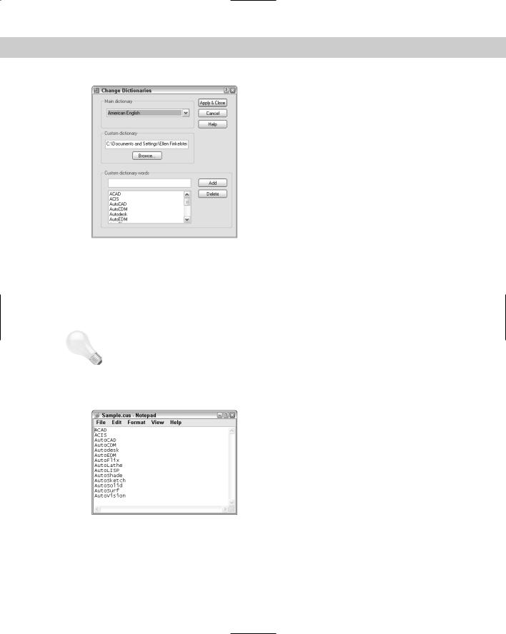
Figure 13-35 shows sample.cus opened in Notepad, the Windows text editor.
Figure 13-35: Open sample.cus in Notepad so that you can edit it directly.
You can use a different custom dictionary. It can be useful, for example, to use the same dictionary in your drawing as you use in your word processor. For example, here’s how to use the Microsoft Word dictionary: