

- •Foreword
- •Preface
- •Is This Book for You?
- •How This Book Is Organized
- •How to Use This Book
- •Doing the Exercises
- •Conventions Used in This Book
- •What the Icons Mean
- •About the CD-ROM
- •Other Information
- •Contacting the Author
- •Acknowledgments
- •Contents at a Glance
- •Contents
- •Getting Acquainted with AutoCAD and AutoCAD LT
- •Starting AutoCAD and AutoCAD LT
- •Creating a New Drawing
- •Using the AutoCAD and AutoCAD LT Interface
- •Creating Your First Drawing
- •Saving a Drawing
- •Summary
- •Creating a New Drawing from a Template
- •Working with Templates
- •Opening a Drawing with Default Settings
- •Opening an Existing Drawing
- •Using an Existing Drawing as a Prototype
- •Saving a Drawing Under a New Name
- •Summary
- •The Command Line
- •Command Techniques
- •Of Mice and Pucks
- •Getting Help
- •Summary
- •Typing Coordinates
- •Displaying Coordinates
- •Picking Coordinates on the Screen
- •Locating Points
- •Summary
- •Unit Types
- •Drawing Limits
- •Understanding Scales
- •Inserting a Title Block
- •Common Setup Options
- •The MVSETUP Command
- •Summary
- •Using the LINE Command
- •Drawing Rectangles
- •Drawing Polygons
- •Creating Construction Lines
- •Creating Rays
- •Summary
- •Drawing Circles
- •Drawing Arcs
- •Creating Ellipses and Elliptical Arcs
- •Making Donuts
- •Placing Points
- •Summary
- •Panning
- •The ZOOM Command
- •Aerial View
- •Named Views
- •Tiled Viewports
- •Snap Rotation
- •User Coordinate Systems
- •Isometric Drawing
- •Summary
- •Editing a Drawing
- •Selecting Objects
- •Summary
- •Copying and Moving Objects
- •Using Construction Commands
- •Creating a Revision Cloud
- •Hiding Objects with a Wipeout
- •Double-Clicking to Edit Objects
- •Grips
- •Editing with the Properties Palette
- •Selection Filters
- •Groups
- •Summary
- •Working with Layers
- •Changing Object Color, Linetype, and Lineweight
- •Working with Linetype Scales
- •Importing Layers and Linetypes from Other Drawings
- •Matching Properties
- •Summary
- •Drawing-Level Information
- •Object-Level Information
- •Measurement Commands
- •AutoCAD’s Calculator
- •Summary
- •Creating Single-Line Text
- •Understanding Text Styles
- •Creating Multiline Text
- •Creating Tables
- •Inserting Fields
- •Managing Text
- •Finding Text in Your Drawing
- •Checking Your Spelling
- •Summary
- •Working with Dimensions
- •Drawing Linear Dimensions
- •Drawing Aligned Dimensions
- •Creating Baseline and Continued Dimensions
- •Dimensioning Arcs and Circles
- •Dimensioning Angles
- •Creating Ordinate Dimensions
- •Drawing Leaders
- •Using Quick Dimension
- •Editing Dimensions
- •Summary
- •Understanding Dimension Styles
- •Defining a New Dimension Style
- •Changing Dimension Styles
- •Creating Geometric Tolerances
- •Summary
- •Creating and Editing Polylines
- •Drawing and Editing Splines
- •Creating Regions
- •Creating Boundaries
- •Creating Hatches
- •Creating and Editing Multilines
- •Creating Dlines
- •Using the SKETCH Command
- •Digitizing Drawings with the TABLET Command
- •Summary
- •Preparing a Drawing for Plotting or Printing
- •Creating a Layout in Paper Space
- •Working with Plot Styles
- •Plotting a Drawing
- •Summary
- •Combining Objects into Blocks
- •Inserting Blocks and Files into Drawings
- •Managing Blocks
- •Using Windows Features
- •Working with Attributes
- •Summary
- •Understanding External References
- •Editing an Xref within Your Drawing
- •Controlling Xref Display
- •Managing Xrefs
- •Summary
- •Preparing for Database Connectivity
- •Connecting to Your Database
- •Linking Data to Drawing Objects
- •Creating Labels
- •Querying with the Query Editor
- •Working with Query Files
- •Summary
- •Working with 3D Coordinates
- •Using Elevation and Thickness
- •Working with the User Coordinate System
- •Summary
- •Working with the Standard Viewpoints
- •Using DDVPOINT
- •Working with the Tripod and Compass
- •Getting a Quick Plan View
- •Shading Your Drawing
- •Using 3D Orbit
- •Using Tiled Viewports
- •Defining a Perspective View
- •Laying Out 3D Drawings
- •Summary
- •Drawing Surfaces with 3DFACE
- •Drawing Surfaces with PFACE
- •Creating Polygon Meshes with 3DMESH
- •Drawing Standard 3D Shapes
- •Drawing a Revolved Surface
- •Drawing an Extruded Surface
- •Drawing Ruled Surfaces
- •Drawing Edge Surfaces
- •Summary
- •Drawing Standard Shapes
- •Creating Extruded Solids
- •Drawing Revolved Solids
- •Creating Complex Solids
- •Sectioning and Slicing Solids
- •Using Editing Commands in 3D
- •Editing Solids
- •Listing Solid Properties
- •Summary
- •Understanding Rendering
- •Creating Lights
- •Creating Scenes
- •Working with Materials
- •Using Backgrounds
- •Doing the Final Render
- •Summary
- •Accessing Drawing Components with the DesignCenter
- •Accessing Drawing Content with Tool Palettes
- •Setting Standards for Drawings
- •Organizing Your Drawings
- •Working with Sheet Sets
- •Maintaining Security
- •Keeping Track of Referenced Files
- •Handling Errors and Crashes
- •Managing Drawings from Prior Releases
- •Summary
- •Importing and Exporting Other File Formats
- •Working with Raster Images
- •Pasting, Linking, and Embedding Objects
- •Summary
- •Sending Drawings
- •Opening Drawings from the Web
- •Creating Object Hyperlinks
- •Publishing Drawings
- •Summary
- •Working with Customizable Files
- •Creating Keyboard Shortcuts for Commands
- •Customizing Toolbars
- •Customizing Tool Palettes
- •Summary
- •Creating Macros with Script Files
- •Creating Slide Shows
- •Creating Slide Libraries
- •Summary
- •Creating Linetypes
- •Creating Hatch Patterns
- •Summary
- •Creating Shapes
- •Creating Fonts
- •Summary
- •Working with Menu Files
- •Customizing a Menu
- •Summary
- •Introducing Visual LISP
- •Getting Help in Visual LISP
- •Working with AutoLISP Expressions
- •Using AutoLISP on the Command Line
- •Creating AutoLISP Files
- •Summary
- •Creating Variables
- •Working with AutoCAD Commands
- •Working with Lists
- •Setting Conditions
- •Managing Drawing Objects
- •Getting Input from the User
- •Putting on the Finishing Touches
- •Summary
- •Understanding Local and Global Variables
- •Working with Visual LISP ActiveX Functions
- •Debugging Code
- •Summary
- •Starting to Work with VBA
- •Writing VBA Code
- •Getting User Input
- •Creating Dialog Boxes
- •Modifying Objects
- •Debugging and Trapping Errors
- •Moving to Advanced Programming
- •A Final Word
- •Installing AutoCAD and AutoCAD LT
- •Configuring AutoCAD
- •Starting AutoCAD Your Way
- •Configuring a Plotter
- •System Requirements
- •Using the CD with Microsoft Windows
- •What’s on the CD
- •Troubleshooting
- •Index

Chapter 13 Creating Text 319
Creating Tables
Tables, often called schedules, are very common in drawings. Since the beginning of time, it seems, you had to build your own tables by drawing horizontal and vertical lines and fitting text in the resulting boxes.
New |
Finally, there is a table feature that lets you create and edit fully formatted tables. You can |
Feature |
save your formatting in table styles for consistency among drawings. Like text styles, you |
|
|
|
should save table styles in your templates. |
Inserting a table
To insert a table, choose Table from the Draw toolbar to start the new TABLE command. The Insert Table dialog box opens, as shown in Figure 13-21.
Figure 13-21: Use the Insert Table dialog box to create a table in your drawing.
On the left side of the Insert Table dialog box, you see a preview of how the table will look. By default, you see the Standard table style or the last table style you used. Choose the table style you want from the Table Style Name drop-down list. In the next section, I explain how to define a table style.
In the Insertion Behavior section of the dialog box, choose from one of the following options:
Specify insertion point: You place the table in your drawing by specifying an insertion point. You use the Column and Row Settings section to specify the number of columns and their width as well as the number of rows and their height (in terms of lines of text).
Specify window: You pick a point at the upper-left corner of the table and then move the mouse to specify the lower-right corner. You use the Column and Rows Settings section to specify the number of columns and the line height of the rows. As you move the mouse to the right, the columns widen and as you move the mouse downward, additional rows are added. Click when you see the size that you want.
320 Part II Drawing in Two Dimensions
|
If the table style shown is what you want, click OK. Then specify an insertion point or a win- |
|
|
dow to place the table. |
|
Cross- |
|
You can also create a table using a table tool on a tool palette. For more information on tool |
Reference |
palettes, see Chapter 26. |
|
|
|
|
|
Specifying a table style |
|
You have a great deal of control over how your table looks. You can make it plain or fancy. To |
|
design your table, you create a table style by choosing Format Table Style to open the Table |
|
Style dialog box, shown in Figure 13-22. |
Tip |
You can also access the Table Style dialog box by clicking the Ellipsis button in the Table Style |
|
Settings section of the Table dialog box (see Figure 13-21). |
Figure 13-22: The Table Style dialog box gives you the tools to create tables with style.
On the left side of the Table Style dialog box, is a list of styles. From the List drop-down box, you can choose to display all styles or only styles that are in use in your drawing. To make a table style current., choose the style that you want and click Set Current.
New |
An easier way to make a table style current is to choose the table style from the new Table |
Feature |
Style drop-down list on the Styles toolbar. Choose your table style before you start to create |
|
|
|
a table. You can also import table styles from the DesignCenter. (For more information on |
|
the DesignCenter, see Chapter 26.) |
To create a new style, click the New button. In the Create New Table Style dialog box, enter a Name in the New Style Name text box. From the Start With drop-down list, choose an existing table style as a basis for your new style. The new table style inherits the properties of this existing style so that you have to specify only the differences that you want. Then click Continue to open the New Table Style dialog box, as shown in Figure 13-23.
Chapter 13 Creating Text 321
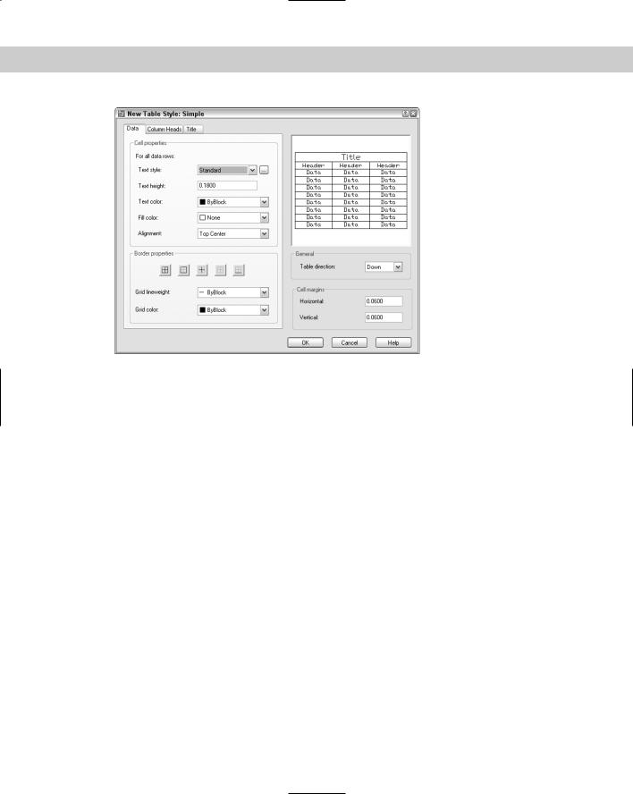
Figure 13-23: The New Table Style dialog box is the place to define a new table style.
As you define your new table style, the preview panel at the right shows you the results. In this dialog box, you use the various tabs to define the formatting for the data in the cells of the table, for column headings, and for the table’s main title. The three tabs are exactly the same, although they have slightly varying defaults. On the Column Heads tab, uncheck the Include Header Row checkbox if you don’t want to create column heads. On the Title tab, uncheck the Include Title Row checkbox if you don’t want a title cell.
Define your table style using the sections of the New Table Style dialog box.
Cell properties
Choose a text style from the Text Style drop-down list. If you don’t have a suitable text style, click the ellipsis button to the right of the drop-down list to open the Text Style dialog box. You can then define a text style. When you’re done, close the Text Style dialog box and your new text style is available in the New Table Style dialog box.
Enter a text height in the Text Height box. Choose a text color from the Text Color drop-down list. The default is ByBlock which means that the text color is the same as the table itself — which is a block. (I explain blocks and the ByBlock attribute in Chapter 18.) You can also choose ByLayer which gives the text the properties of the current layer.
Use the Fill Color drop-down list to specify the background color of the cells. The default is None, which shows the background color of your drawing area.
Use the Alignment drop-down list to specify the text alignment within each cell. For example, you might want to use Middle Center for the table and column headings, but Middle Left for the data cells.
322 Part II Drawing in Two Dimensions
Border properties
Choose one of the border buttons to specify which borders you want to see. For example, for the data cells, if you choose Outside Borders, the data area of the table will not have any grid lines between the cells, only around the outside of the data cells.
Caution |
If you inadvertently create a table style with outside borders or no borders, you may not |
|
notice the absence of borders in your drawing — grid lines show between the cells so that |
|
you can more easily fill in the table. Choose Plot Preview on the Standard toolbar to see the |
|
final result more accurately. |
Choose a grid lineweight from the Grid Lineweight drop-down list. For example, you may want a slightly thicker lineweight for the title cell. Then choose a color from the Grid Color dropdown list. You can leave the ByBlock default and the color will match the layer of the table.
General
In the General section, choose a direction for the table. The default direction is Down — the table title is at the top, and you enter data from the top to the bottom. You can choose the Up direction, in which case the title is at the bottom of the table, and you enter data from the bottom to the top.
Cell margins
The cells margins are the space between the text and the cell borders. The horizontal margins affect the left and right sides of the text. The vertical margins affect the top and bottom of the text. Enter a value in the Horizontal and Vertical text boxes.
When you’re done, click OK to return to the Table Style dialog box. Click Close to return to your drawing.
Entering data into a table
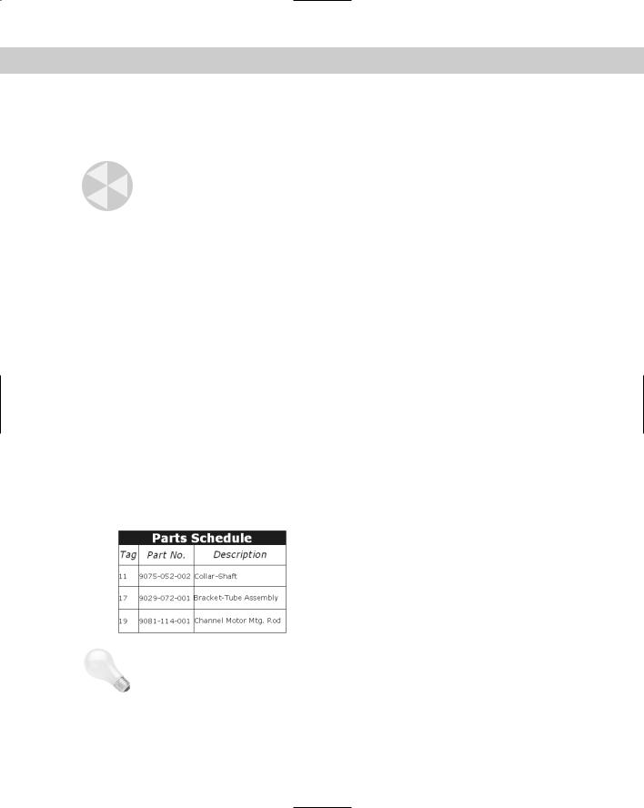
After you’ve placed a table, you enter data into the table. The cursor is automatically placed in the first cell and you just start typing. Press Tab to move to the next cell. Continue in this way until you have completed the table. Figure 13-24 shows an example of a table.
Figure 13-24: A nicely styled schedule of parts.
Tip |
You can create a complete table on the fly by importing data from Microsoft Excel. Select the |
|
data in Excel and copy it to the Windows clipboard. In AutoCAD, choose Edit Paste Special. |
|
In the Paste Special dialog box, choose AutoCAD Entities and click OK. At the prompt, pick an |
|
insertion point. |

Chapter 13 Creating Text 323
You can insert a field into any cell in a table. For more about fields, see the “Inserting Fields” section, later in this chapter. You can also insert blocks into a table. (I explain blocks in Chapter 18.) After you’ve finished entering text, click a blank cell to select that cell. Then rightclick and choose Insert Block.
Modifying a table
You may need to change the data in a table or you may want to change the way the table looks. Either way, you can modify a table easily. However, you need to know some of the techniques involved, because tables in AutoCAD and AutoCAD LT are a little different from tables in your word processor.
Changing the text
Changing the text of a table is like changing any multiline text. Double-click the text inside a table, being sure not to double-click the grid lines; the Multiline Text Editor opens. You can use any of the techniques for editing text that I discuss in the “Editing paragraph text” section earlier in this chapter. You can change the properties of the text so that they don’t match the table style. For example, you can change the height or font of the text.
Changing table properties
You can also change properties of the table itself. If you double-click the table itself (that is, any of the grid lines), the Properties palette opens. Here, you can modify any conceivable table property, including its layer, its color, the number of rows or columns, or any of its style properties. If you want to revert to old-fashioned lines, you can explode the table. Of course, you can no longer edit the table as a table any more. You just have lines and text.
To select the entire table, click on any gridline of the table. You see grips at the corners of the table and at several other cell junctions. If you select the table and right-click you can use the shortcut menu to make additional changes to the table. For example, you can size columns or rows equally or remove property overrides. If you make a change to a cell, such as the cell’s alignment or color, you can use the Remove All Property Overrides item on the shortcut menu to change the cell’s properties back to match the rest of the table.
To select a cell, click inside that cell. You can then right-click and use the shortcut menu. Some of the more-useful items are:
Cell alignment: Changes the alignment of the text in the cell, using the standard textalignment options available for multiline text.
Cell borders: Opens the Cell Border Properties dialog box, where you can specify border properties for that individual cell.
Match cell: Matches cell properties. At the Select destination cell: prompt on the command line, pick another cell that you want to have the same properties. The prompt repeats until you press Enter.
Insert block: Opens the Insert a Block in a Table Cell dialog box, where you can select the block that you want to insert, specify the block’s alignment in the cell, as well as set its scale and rotation angle. If you select the Autofit checkbox, the block is automatically scaled to fit the table cell.
Insert columns: Inserts a column. You can choose to insert the column to the right or to the left of the current cell’s column.

324 Part II Drawing in Two Dimensions
Delete columns: Deletes the column that the current cell is in.
Insert rows: Inserts a row. You can choose to insert the row above or below the current cell’s row.
Delete rows: Deletes the row that the current cell is in.
Size rows equally: Makes all your rows an equal height.
Remove all property overrides: Removes any formatting that you applied to the selected cell.
Delete cell contents: Deletes any text or block in the current cell.
Merge: Merges two or more cells together. You can choose to merge all the selected cells into one cell, to merge them by row, or to merge them by column.
Unmerge cells: Unmerges merged cells and recreates all the original cells.
You can select multiple cells and apply changes to those cells. To select multiple cells, use one of the following techniques:
Click inside one cell and drag over the other cells that you want to select. Release the mouse button at the last cell.
Click inside one cell, hold down Shift, and click inside the last cell that you want to select.
Tip |
To enter the same text in multiple cells, select the cells. Then open the Properties palette and |
|
enter the text in the Contents item. The text appears in all the selected cells. |
|
When you select multiple cells, you can also merge the cells. Right-click and choose Merge Cells |
|
from the shortcut menu. By merging cells, you can create fairly complex table structures. |
|
You can also edit tables using grips. To understand editing tables with grips, imagine that the |
|
left side of the table is the stable side, while the right side of the table is the flexible side. The |
|
top-left grip is the base point for the entire table. You can do the following edits with grips: |
Upper-left grip: Moves the entire table.
Upper-right grip: Stretches the table horizontally. As you change the width of the table, the columns also stretch proportionally.
Lower-left grip: Stretches the table vertically. As you change the height of the table, the rows also stretch proportionally.
Lower-right grip: Stretches the table both vertically and horizontally. The columns and rows adjusts proportionally.
Top of column grip: Adjusts the width of the column to the left of the grip. The entire table adjusts accordingly. If you press Ctrl while moving a column grip, the adjacent columns adjust but the width of the table remains unchanged.
You can export a table to comma-delimited (.csv) format. You can then open the table data with a database or spreadsheet program. To export a table, follow these steps:
1.Select the table.
2.Right-click and choose Export.
Chapter 13 Creating Text 325
On the
CD-ROM
3.In the Export Data dialog box, choose a name and location for the file.
4.Click Save.
The drawing used in the following Step-by-Step exercise on creating tables, ab13-05.dwg, is in the Results folder on the CD-ROM.
STEP-BY-STEP: Creating Tables
1.Open ab13-05.dwg from the CD-ROM. If you did the last exercise, you can open the drawing from your AutoCAD Bible folder.
2.Save the file as ab13-06.dwg in your AutoCAD Bible folder. This is the same plat drawing used in the preceding Step-by-Step exercise.
3.Choose Table from the Draw toolbar. In the Insert Table dialog box, click the Ellipsis button to the right of the Table Style Name drop-down list.
4.In the Table Style dialog box, click New. In the Create New Table Style dialog box, enter AcreageSchedule in the New Style Name text box. The Start With text box should read Standard. Click Continue. The New Table Style dialog box opens.
5.From the Text Style drop-down list, choose ROMANS. In the Text Height text box, enter
12.5.Because you want the numbers in the table to be right-aligned, choose Middle Right from the Alignment drop-down list. In the Cell Margins section, change both the Horizontal and Vertical text box values to 5.
6.Click the Column Heads tab. Make sure that the Include Header Row checkbox is checked. Again set the Text Style to ROMANS and the Text Height to 12.5. Leave the alignment as Middle Center.
7.Click the Title tab. Make sure that the Include Title Row check box is checked. Make the following changes:
•Text Style: ROMANT (for a different look).
•Text Height: 13.5 to make the title text bigger than the rest of the table text.
•Text Color: Click the Text Color drop-down list and choose Select Color. From the Select Color dialog box, choose the lightest gray color on the Index Color tab. Click OK to return to the New Table Style dialog box.
•Fill Color: Click the Fill Color drop-down list and choose Blue.
•Grid Color: In the Border Properties section, click the Grid Color drop-down list and choose Blue to match the fill.
8.Click OK to return to the Table Style dialog box and click Set Current. Then click Close to return to the Insert Table dialog box.
9.In the Insertion Behavior section of the dialog box, make sure that the insertion behavior is set to Specify insertion point. In the Columns & Rows section, set the number of columns to 2 and the column width to 100. Set the number of data rows to 4. The row height should be 1. Click OK.