

Chapter 3 Using Commands |
35 |
Some of the tools have flyouts, which are like toolbar flyouts. Click the small arrow and the flyout appears, containing other command buttons. Click the command button that you want in order to start that command.
Cross- |
You can use tool palettes to insert objects, fill in closed areas, and add other content. For more |
Reference |
information, see Chapter 26. I also explain how to customize tool palettes in Chapter 29. |
|
The Command Line
Every command that you choose from a toolbar button, menu, or tool palette is echoed on the command line. You can also execute a command by typing it directly on the command line.
Understanding command names
All commands have a special one-word command name. This may or may not be the same as the wording that appears on the toolbar’s tooltip or on the menu. But you can be sure of one thing — every command can be executed by typing its name on the command line. Fast typists often prefer to use the command line because they find it faster than searching for a command on a menu or toolbar. Most users use a combination of command line, menu, and toolbar commands.
Some of the commands are easy to type, such as LINE or ARC. Others are long and harder to remember, such as HATCHEDIT, DDPTYPE, or IMAGEATTACH. Command names such as these can quickly drive you to use a menu or toolbar.
Cross- If you like typing commands, you can create short versions of the command names, called Reference aliases. Many are already included with AutoCAD and AutoCAD LT. Aliases are covered in
Chapter 29.
You can edit what you have typed on the command line. If you type a long command and make a mistake, you can backspace up to the mistake and retype the last part correctly. Table 3-1 shows how to use the keyboard edit keys to edit the command line.
|
Table 3-1: Command-Line Editing Keys |
|
|
Key |
Function |
|
|
Backspace |
Backspaces through the text on the command line, erasing each letter as it backspaces. |
Left arrow |
Moves backward through the text of the command, without erasing. |
Right arrow |
Moves forward through the text of the command, without erasing. |
Home |
Moves the command-line cursor to the beginning of the text. |
End |
Moves the command-line cursor to the end of the text. |
Insert |
Toggles between Insert/Overwrite mode. Insert mode inserts text. Overwrite mode types |
|
over existing text. Note that there is no visual confirmation of which mode you are in. |
Delete |
Deletes the character to the right of the cursor on the command line. |
Ctrl+V |
Pastes text from the Windows Clipboard. |
|
|

36 |
Part I AutoCAD and AutoCAD LT Basics |
|
You can scroll through and reuse previous command-line entries. To repeat the last line you |
|
entered, press the up arrow. Press Enter to execute it. To see more of the command-line entries, |
|
press F2 on your keyboard to open the Text Window. Scroll until you find the entry you want, |
|
highlight it, and then right-click and choose Paste To CmdLine from the shortcut menu. You |
|
now see the highlighted text on the current command line. You can also copy selected text from |
|
the command-line history or the entire history to the Clipboard. Or choose Recent Commands |
|
on the shortcut menu and choose one of the commands from the submenu that appears. |
Tip |
Switching from the mouse to the keyboard and back is time-consuming. In general, if you’re |
|
picking points using the mouse (covered in Chapter 4), using menus and toolbars to give |
|
commands is faster. If you’re typing coordinates as you did in Chapter 1, your hands are |
|
already at the keyboard, so typing commands at the keyboard is easier. |
Responding to command options
Many commands have options from which you need to choose. The format for command options is as follows:
current instruction or [options] <current value>:
The current instruction explains what you need to do. For example, if you choose an editing command, the prompt usually instructs you to “Select objects.” The text in the square brackets lists the various options available for the command. The angled brackets tell you the current or default value for the command, if any.
Choosing an option is easy:
To choose an option on the command line, type the one or two letters that are capitalized in the option name — usually (but not always) the first letter(s) of the option. You can type the letter(s) in lowercase. Press Enter.
To choose a default option or current value on the command line, which appears in angled brackets, as in <Real time>, simply press Enter or provide the point or value required.
To choose an option without going to the command line, right-click in the drawing area and choose one of the options from the shortcut menu. This works best for options that won’t need any numerical input on the command line. Choosing options from a shortcut menu on the screen is an example of heads-up drawing, which increases efficiency because you don’t need to stop to look down at the keyboard.
At this point, additional options may appear, or you may be prompted to select a point or an object.
In the following exercise, you practice using command options. In Chapter 1, you typed coordinates to specify points. Here you pick points on the screen directly with the mouse.
STEP-BY-STEP: Using Command Options
1.Open a new drawing using the acad.dwt template.
2. Choose Arc on the Draw toolbar.
3.Look at the command line. You see the following prompt:
Specify start point of arc or [Center]:
Chapter 3 Using Commands |
37 |
Specifying the start point is the main instruction, but you have an option to specify the center of the arc. Move the mouse cursor anywhere in the middle of the screen, and click to specify the start point. This is called picking a point.
4.Now you see the following prompt:
Specify second point of arc or [Center/End]:
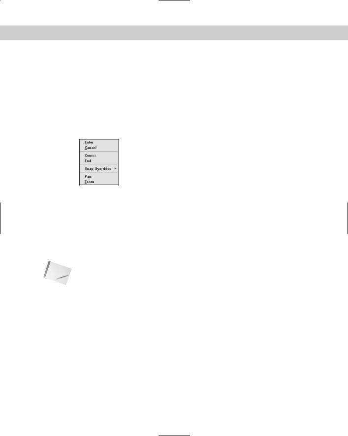
Say that you want to specify the end of the arc. Because specifying the second point is the main instruction, right-click to display the shortcut menu, shown in Figure 3-5, and choose End, one of the options. The program responds with the Specify end point of arc: prompt.
Figure 3-5: Using the shortcut menu to choose the End option of the
ARC command.
5.Pick another point on the screen fairly close to the first one.
6.At the Specify center point of arc or [Angle/Direction/Radius]: prompt, type r .
7.At the Specify radius of arc: prompt, type 2 . The arc is drawn and the command ends. Don’t worry at this point if the arc is partly off the screen or doesn’t appear as you expect. (It’s possible to pick two endpoints for the arc that can’t have a radius of 2. If this happens, try again with two different points.)
Do not save this drawing.
Note |
You may have noticed an underscore (_) before each command. This mark allows translation |
|
to foreign languages and can be ignored. |
Sometimes a command has so many options that AutoCAD or AutoCAD LT opens a dialog box. This method offers a more structured way of letting you choose command options.
Command Techniques
To make working with commands easier, AutoCAD and AutoCAD LT offer shortcuts for repeating and canceling commands as well as sophisticated undo and redo options. You can also use certain commands after you have started another command.
You can have more than one command in process concurrently, one in each open drawing. You can switch from one open drawing to another without interrupting your commands. For example, if you’re in the middle of drawing a circle in one drawing, you can open a new drawing and start another command to get some information you need for the circle. Then you can return to the first drawing and complete the circle.
38 |
Part I AutoCAD and AutoCAD LT Basics |
Tip
Tip
Repeating commands
The most common way to repeat a command you have just used is to press Enter at the Command: prompt. The most recent command appears again.
You can also press the Spacebar at the Command: prompt to repeat a command you just used. This technique works well if you want to keep one hand on the mouse and use the other hand to press the Spacebar.
If you know in advance that you’ll be using a command several times, you can use another technique — type multiple . At the Enter command name to repeat: prompt, type the command name on the command line. The command automatically reappears on the command line until you press the Esc key. For example, you could type multiple and then arc if you knew you were going to draw several arcs in a row. To stop repeating the command, press Esc.
If you create a toolbar button that executes a customized set of actions, right-click and choose the top option of the shortcut menu to repeat the action of the toolbar button. You cannot press Enter to get this effect.
Canceling commands
Sometimes you start a command and then realize you don’t need it. In this situation, you can cancel the command and then choose a different command. Press Esc to cancel a command that you’ve already started. The Command: prompt reappears.
In the following exercise, you practice the techniques for repeating and canceling commands.
STEP-BY-STEP: Repeating and Canceling Commands
1.Start a new drawing using the acad.dwt or aclt.dwt template.
2.Choose Circle on the Draw toolbar.
3.At the Specify center point for circle or [3P/2P/Ttr (tan tan radius)]: prompt, pick a center point anywhere near the center of the screen.
4.At the Specify radius of circle or [Diameter]: prompt, move the mouse cursor and click the pick button when you see a medium-sized circle. The circle appears in the drawing area.
5.Press Enter. The CIRCLE command appears again on the command line.
6.Follow these prompts:
Specify center point for circle or [3P/2P/Ttr (tan tan radius)]:
Right-click and choose 2P from the shortcut menu.
Specify first end point of circle’s diameter: Pick any point on the screen.
Specify second end point of circle’s diameter: Press Esc.
AutoCAD or AutoCAD LT responds with *Cancel* and returns you to the Command: prompt without finishing the command that was in progress.
Do not save this drawing.
Chapter 3 Using Commands |
39 |
|
Undoing a command |
|
|
Most Windows applications offer Undo and Redo commands on the Standard toolbar. AutoCAD |
|
|
and AutoCAD LT are no different. Some applications remember a list of your last few actions so |
|
|
that you can undo them one by one. AutoCAD and AutoCAD LT remember every command you |
|
|
execute starting from the time you open a drawing. You can therefore undo every action and |
|
|
return your drawing to its condition when you opened it. |
|
Tip |
The Undo button on the Standard toolbar lists the commands you’ve executed so that you |
|
|
can quickly see how many commands you want to undo. |
|
|
Actually, there are a few obvious exceptions. For example, if you print a drawing, you can’t |
|
|
unprint it, and you can’t unsave a drawing, either. Similarly, commands that provide you with |
|
|
information, such as the coordinates of a point, cannot be undone. |
|
Note |
Some commands have their own undo options. I explain these undo options when I discuss |
|
|
these commands throughout the book. |
|
|
|
Each time you click Undo on the Standard toolbar, you undo one command. If you |
|
|
click the down arrow to the right of the Undo button and choose the bottom-most |
|
command, you undo all the commands and get the message: |
|
|
Everything has been undone |
|
|
When you start UNDO, you see the following options on the command line: |
|
|
Enter the number of operations to undo or |
|
|
[Auto/Control/BEgin/End/Mark/Back] <1>: |
|
|
Enter the number of operations to undo is the default instruction. If you type a num- |
|
|
ber, such as 3, you undo your last three commands. This action is equivalent to choosing the |
|
|
third command on the Undo button’s drop-down list. Table 3-2 explains the other options: |
|
|
|
|
|
|
Table 3-2: Options of the UNDO Command |
|
|
|
|
Option |
How to Use It |
|
|
|
|
Auto |
Can be On or Off. Applies to a menu item that executes more than one command at a |
|
|
time. When Auto is On (the default), the entire menu item is undone in one step. When |
|
|
Auto is Off, UNDO undoes each step one at a time. |
|
Control |
Offers three sub-options. All, the default, gives you the full UNDO capability. None disables |
|
|
the UNDO command. One enables you to undo only one step at a time, effectively turning |
|
|
the UNDO command into the U command. |
|
Begin |
Works with the End option. This starts a group at the current point of the list of |
|
|
commands. Then, when you use the End option, UNDO undoes all the commands in the |
|
|
group. The U command also undoes everything within a group. |
|
End |
Marks the end of all commands in the group created by using the Begin option. |
|
Mark |
This option works with the Back option. It is somewhat similar to the Begin option, but |
|
|
you can place several marks as you work. |
|
Back |
When you use this option, AutoCAD or AutoCAD LT undoes only to the most recent Mark |
|
|
point. The next Back option you use undoes to the Mark point before that. |
|
|
|
40 |
Part I AutoCAD and AutoCAD LT Basics |
Note The word Group means that a group of commands is being undone. However, the word Group is sometimes used even for a single command. This use of the word Group is not significant and can be ignored.
Using the Back option when no Mark has been created undoes everything you have done in a drawing session! Luckily, you get the following warning message:
This will undo everything. OK? <Y>
Type n if you do not want to undo everything.
Tip The Begin/End and Mark/Back options are useful when you’re trying something new and want to be able to undo a whole series of commands in one UNDO command, in case things don’t work out as planned.
Redoing a command
If you undo a command, you might realize that you want to undo the undo. This is called redoing a command. Don’t confuse redoing a command with repeating a command. Redoing only applies when you have just undone a command.
The MREDO command on the Standard toolbar redoes the effect of the previous UNDO commands. You can also redo multiple UNDO commands. You can choose
recently undone commands from the Redo drop-down list.
Note The old REDO command that only redoes one command still exists, but the Redo button on the Standard toolbar executes the MREDO command that redoes multiple UNDO commands.
In the following exercise, you practice using the UNDO and MREDO commands.
STEP-BY-STEP: Undoing and Redoing Commands
1.Start a new drawing using acad.dwt or aclt.dwt as the template.
2.Choose Line on the Command Tools tab of the tool palette. (If necessary, press Ctrl+3 to display the tool palette and click the Command Tools tab.)
3.Follow the prompts to draw one line, and press Enter to end the command.
4.On the Command Tools tab of the tool palette, click the right arrow to the right of the Line button to open the flyout. Choose Arc.
5.Using the default options, pick any three points to draw an arc.
6.On the Command Tools tab of the tool palette, click the right arrow to the right of the Arc button to open the flyout. Choose Circle.
7.Pick one point to be the center of the circle and another nearby point to specify the radius. Your drawing now contains a line, an arc, and a circle, and looks something like Figure 3-6. Of course, your objects will look different because you picked different points.
8. Click the Undo button on the Standard toolbar. The circle disappears.

Chapter 3 Using Commands |
41 |
Cross-
Reference
9.Click the down arrow to the right of the Undo button on the Standard toolbar. Choose Line. The arc and the line disappear.
10.Click the down arrow to the right of the Redo button on the Standard toolbar. Choose Circle. All three objects reappear because they were undone by the pre-
vious UNDO commands.
Do not save this drawing. If you are continuing, keep the drawing on the screen for the next exercise.
Figure 3-6: Your drawing should contain a line, an arc, and a circle.
The OOPS command restores the most recently erased object or set of objects, even if you have used other commands in the meantime. See Chapter 18 for further information.
Using one command within another command
Certain commands can be used within another command. These are called transparent commands. After a transparent command is completed, the original command continues its regular operation. Many transparent commands help you display the drawing differently so that you can complete the original command easily. Other transparent commands change settings. In fact, almost any command that doesn’t select objects, create new objects, cause regeneration, or end the drawing session can be used transparently. When you start transparent commands from toolbars or menus, they are automatically transparent. If you want to type a transparent command on the command line, you need to type an apostrophe (‘) before the command name.
In this exercise, you practice using transparent commands and two commands concurrently.
On the |
The drawing used in the following Step-by-Step exercise on using transparent commands |
CD-ROM |
and two commands concurrently, ab01-01.dwg, is in the Results folder on the CD-ROM. |
STEP-BY-STEP: Using Transparent Commands and Two
Commands Concurrently
1.From the previous exercise, you have a line, an arc, and a circle on the screen. If not, begin a new drawing using acad.dwt as the template and draw a line and an arc anywhere on the screen. (You don’t need the circle.)
2.Choose View Zoom Out. The drawing zooms out, appearing smaller.
3.Choose Open from the Standard toolbar and open ab01-01.dwg from the Results folder on the CD-ROM. This is a drawing of a window.
4.From the Windows taskbar, choose your original drawing.