

Chapter 8 Viewing Your Drawing 137
3.Choose a view from the list of named views.
4.Choose one or more layers. To include all the layers, click Load All. (If you don’t include at least one layer, no objects are loaded. Chapter 11 covers layers.) Click Open.
After you’ve partially opened a drawing, you can open more of the drawing. Choose File Partial Load. This item is only available if the current drawing has been partially opened. AutoCAD opens the Partial Open dialog box. You can change the view. To display the entire drawing (from whatever is loaded), choose the default view, *Extents*. To define a new view on the fly, click the Pick a Window button and define the two diagonal corners of the view you want to see. Check what layers you want to include or click Load All. Click OK to open the drawing with the new view and layers specifications.
Using named views with sheet sets
Sheet sets are a new feature of AutoCAD 2005. (AutoCAD LT doesn’t include this feature.) You can combine layouts from more than one drawing into a sheet set. Sheet sets are a powerful way to organize many layouts. I cover them in detail in Chapter 26. However, at this point you should know that named views have a value beyond helping you display an area of your drawing. They can also turn into your final layout for plotting.
Suppose that you’re drawing a mechanical model with a top view, a side view, and a section view. In the final plot, you want to display these three views on one sheet of paper. Without sheet sets, you would create three floating viewports and individually pan and zoom to get the three views. (For more information on floating viewports, see the “Floating viewports” sidebar in this chapter, as well as Chapter 17.) Using the sheet-set feature, as you work you can create named views of the three parts of the drawing. Then you can use those same views to create the floating viewports for plotting.
Tiled Viewports
Tiled viewports enable you to divide up the screen into rectangular bounding boxes. You can then show a different view of your drawing in each viewport. The purpose of tiled viewports is to help you draw. For example:
Cross-
Reference
You can see the whole drawing in one viewport and a zoomed-in portion of that drawing in another viewport.
You can see widely separated views of a large drawing at one time.
There are two types of viewports — tiled and floating. For more information on floating viewports, see the sidebar of that title in this chapter. For a detailed discussion, turn to Chapter 17.
Actually, you’re already using a tiled viewport because the regular single view of your drawing that you’ve been working with represents the default of a one-tile viewport.
Tiled viewports have the following characteristics:
No matter how many viewports you have, they always collectively take up the entire screen. They are not separate entities but a way of dividing up the screen.
Only one viewport can be active at a time. The active viewport has a bold border.
The crosshairs only appear in the active viewport.
The UCS (User Coordinate System) icon (if set to On) appears in each viewport.

138 Part II Drawing in Two Dimensions
Any change you make to your drawing in one viewport automatically appears in every other viewport (or in viewports that show the part of the drawing where you made the change).
You can create up to 96 viewports — but you’ll never want to create that many!
You can begin a command in one viewport and finish it in another. For example, you can start a line in one viewport, switch to a second viewport, and end the line there.
You can save and restore viewport configurations.
Figure 8-12 shows a drawing divided into three tiled viewports. Each viewport shows a different view of the same drawing.
Figure 8-12: A drawing showing three tiled viewports with a different view in each viewport.
Thanks to Jerry Bottenfield of Clow Valve Company, Oskaloosa, Iowa, for this drawing.
Configuring tiled viewports
Creating tiled viewports involves deciding how you want to divide up the screen. A set of tiled viewports is called a configuration. There are a few simple configurations, but you can create your own by further dividing up any of the viewports. You can also join two viewports. Finally, you can always return to the default of one viewport.
Creating tiled viewports
To add viewports, choose View Viewports. This opens a submenu from which you can choose from the preset configurations, as shown in Figure 8-13.
You can choose to create up to four tiled viewports from the submenu, at which point you respond to the options that appear on the command line. For example, if you choose 2 Viewports, the command responds with the Enter a configuration option [Horizontal/
Chapter 8 Viewing Your Drawing 139
Vertical] <Vertical>: prompt. Right-click and choose Horizontal or Vertical to create two horizontal or vertical viewports. If you choose 4 Viewports, you get four equal viewports, one in each corner. However, if you choose 3 Viewports, you can choose from several options to configure the three viewports.
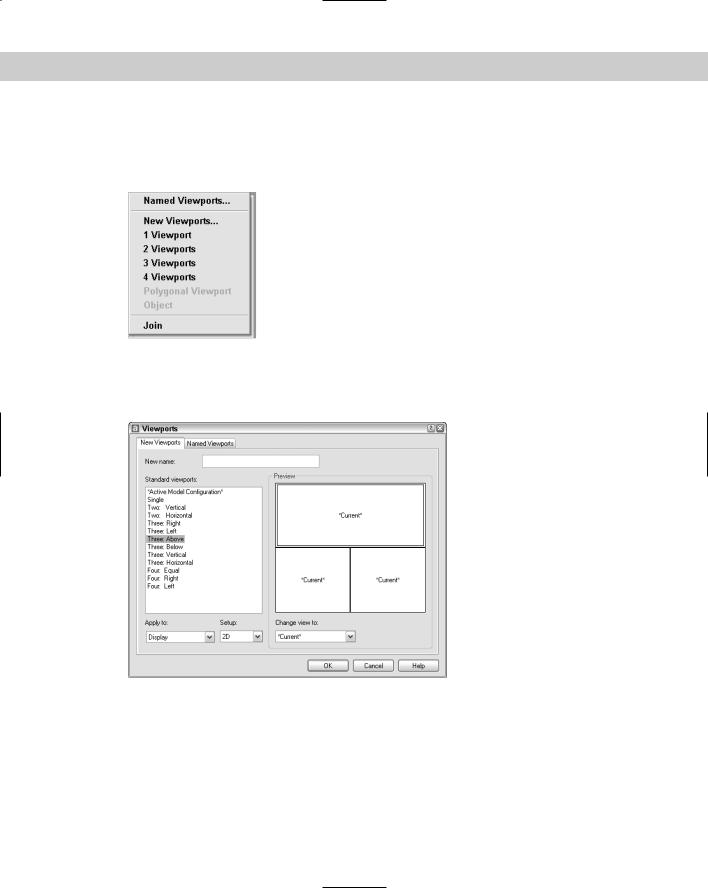
Figure 8-13: The Viewports submenu.
An easier way to configure viewports is to choose New Viewports from the submenu. The Viewports dialog box opens with the New Viewports tab on top, as shown in Figure 8-14. Here you choose the configuration that you want. You see a preview of the configuration.
Figure 8-14: The Viewports dialog box makes it easy to choose a configuration.
If you have named views in your drawing, you can specify a view for each viewport to display. Click a viewport in the Preview pane and choose a named view from the Change View To dropdown list box at the bottom of the dialog box. If your drawing is in 3D, you can choose 3D from the Setup drop-down list box, and AutoCAD creates standard orthogonal views in the viewports. When you’ve specified your viewport configuration, click OK to return to your drawing.
140 Part II Drawing in Two Dimensions
The Viewport dialog box is usually the best place to start creating viewports. However, if the standard configurations do not meet your needs, you can use one of them as a starting point and then use the other options.
Notice the Apply To drop-down list at the bottom-left corner of the Viewports dialog box (New Viewports tab) in Figure 8-14. By default, the tiled viewport configurations apply to the entire display, meaning that they replace your current configuration. You can also choose to apply the configuration to the current viewport. The active viewport has a bold border and crosshairs. To make a viewport active, click anywhere inside that viewport. Then choose View Viewports New Viewports, choose Current Viewport from the Apply To drop-down list, and choose the configuration you want for that viewport.
Let’s say you have four equal viewports, and the top-left viewport is active. If you choose the Four: Equal configuration from the Viewports dialog box while the top-left viewport is active and apply it to the current viewport, the top-left viewport is divided into four viewports. Now you have seven viewports in the drawing.
Removing tiled viewports
One way to remove a tiled viewport is to join it to another viewport. To join one viewport to another, choose View Viewports Join. At the Select dominant viewport <current viewport>: prompt, click the viewport you want to retain or press Enter if you want to retain the current viewport. At the Select viewport to join: prompt, click the adjacent viewport that you want to join into the dominant viewport. When the two viewports merge, you lose the display in this second viewport. The adjacent viewports must together form a rectangle.
The only other way to remove all tiled viewports in one step is to return to the single viewport configuration — choose View Viewports 1 Viewport. The display in the current viewport remains.
Floating viewports
AutoCAD and AutoCAD LT have two types of viewports, tiled viewports, which are discussed here, and floating viewports, which I cover in Chapter 17. These two types of viewports have many similarities, but they have different purposes. Whereas the purpose of tiled viewports is to help you draw and edit your drawing, floating viewports are used to lay out your drawing for plotting.
Floating viewports create layouts, which enable you to treat your screen like a sheet of paper. You create floating viewports and perhaps a title block on this electronic sheet of paper. You can create one or more layouts. Each floating viewport can show a different view of your drawing — just like tiled viewports. But floating viewports then let you plot all those views on one sheet of paper. You can’t do that with tiled viewports, which are just devices to let you temporarily display your drawing in a way that helps you draw and edit. However, you can also draw and edit using floating viewports.
Tiled viewports are covered here because they are appropriate for learning how to draw and edit your drawing. Floating viewports are covered in Chapter 17 because you use them to lay out your drawing for plotting.

Chapter 8 Viewing Your Drawing 141
Using tiled viewports
After you’ve created the viewport configuration that you want, you’re ready to use it. The first step is to create the views you need in each viewport.
Creating viewport views
Creating views in each viewport involves two steps:
1. |
Make a viewport current by clicking anywhere inside it. |
2. |
Zoom and pan until you have the view that you want. |
Tip |
Many users commonly use one viewport to display the entire drawing and the others to display |
|
zoomed-in views of smaller sections. |
Drawing from viewport to viewport
After you have the viewport configuration and views you need, you can start to draw.
One of the great advantages of viewports is that you can draw from one viewport to another. In a large drawing, you may need to draw a line from one end of the drawing to another,
but when you display the entire drawing you can’t see the detail well enough to specify where to start and end the line. The basic steps to draw from one viewport to another are as follows:
Cross-
Reference
1.Click the viewport where you want to start. This might be a small detail of one corner of your drawing.
2.Start the command and specify any options you need. Specify any necessary coordinates as you usually would.
3.To continue the command in a second viewport, click to activate that viewport. Continue the command, specifying coordinates as necessary.
4.You can continue the command in a third viewport by clicking it. Do this until you’ve completed the command. If you have a viewport displaying the entire drawing, you immediately see the results in that viewport as well.
You can also use viewports to edit your drawing. Chapters 9 and 10 cover the commands used to edit your drawing.
All commands except those that change the display — such as zooming, panning, and creating views — can be started in one viewport and continued in another.
Saving and restoring viewport configurations
You can save a tiled viewport configuration. If you find yourself creating a particular configuration over and over, you should save it. Saving a configuration is just a matter of giving it a name. You can then restore it when needed. Viewport configuration names can be up to 255 characters and can include spaces.
142 Part II Drawing in Two Dimensions
Saving a viewport configuration
After you create a viewport configuration that you like, follow these steps to save it:
1.Choose View Viewports New Viewports if you aren’t already in the Viewports dialog box.
2.Type a name in the New name text box.
3.Click OK.
Restoring a viewport configuration
After returning to one viewport or using a different configuration, you can restore a named viewport configuration, as follows:
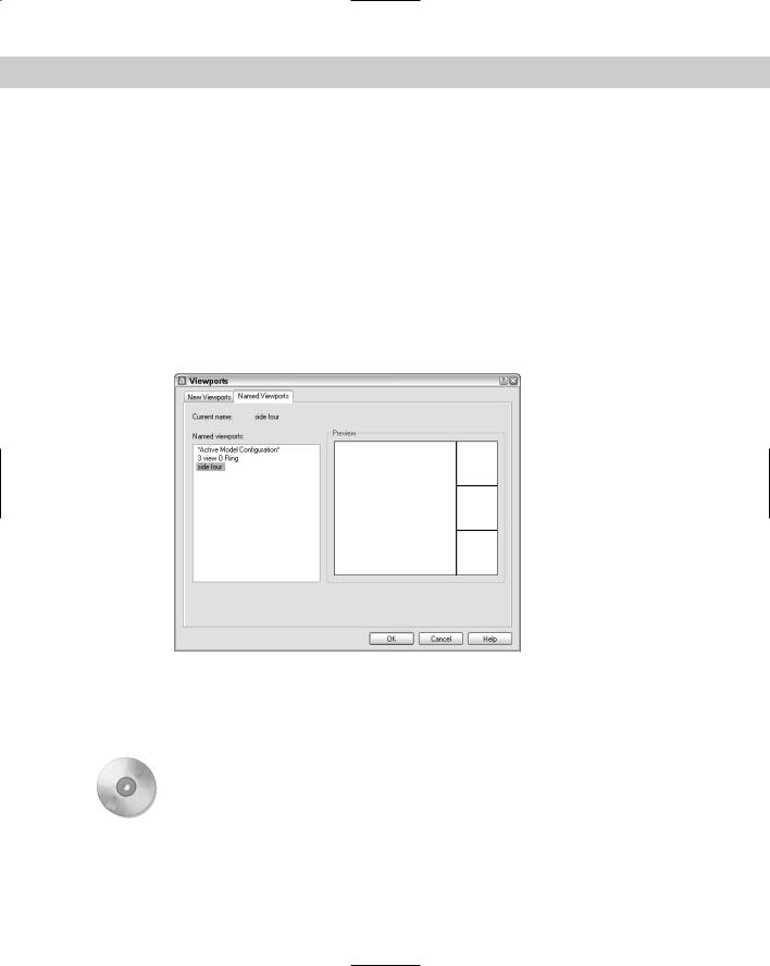
1.Choose View Viewports Named Viewports to open the Viewports dialog box with the Named Viewports tab on top, shown in Figure 8-15.
On the
CD-ROM
Figure 8-15: The Named Viewports tab lists saved viewport configurations.
2.Choose the viewport that you want to restore.
3.Click OK.
The drawing used in the following Step-by-Step exercise on creating, naming, and restoring tiled viewport configurations, a08-c.dwg, is in the Drawings folder on the CD-ROM.
STEP-BY-STEP: Creating, Naming, and Restoring
Tiled Viewport Configurations
1.Open ab08-c.dwg from the CD-ROM.
2.Save the file as ab08-02.dwg in your AutoCAD Bible folder.