

Drawing Curves
and Points
AutoCAD and AutoCAD LT offer a number of ways to create curved objects. You can draw circles, arcs, ellipses, and
donuts (also called doughnuts). In this chapter, I also cover point objects that are neither curves nor lines but don’t deserve their own chapter.
Cross- |
Several complex objects — such as polylines, splines, regions, and |
Reference |
boundaries — involve curves. These are covered in Chapter 16. |
|
Drawing Circles
Circles are common objects in drawings. In mechanical drawings, they often represent holes or wheels. In architectural drawings, they may be used for doorknobs, trash baskets, or trees. In electrical and piping schematics, they are used for various kinds of symbols.
Understanding the circle options
The CIRCLE command provides five ways to draw a circle. To draw a circle, choose Circle from the Draw toolbar. The command responds with the Specify center point for circle or
[3P/2P/Ttr (tan tan radius)]: prompt. Table 7-1 describes how to use these options.
Table 7-1: Five Ways to Draw a Circle
Option |
Description |
|
|
Center Radius |
This option is the default. Specify the center and then |
|
the radius. You can type the radius as a distance or pick |
|
a point on the circumference. |
Center Diameter |
Specify the center. Type d and type the length of the |
|
diameter or pick a point to specify the diameter. |
C 7H A P T E R
In This Chapter
Drawing circles
Drawing arcs
Creating ellipses
Drawing donuts
Creating points
Continued
108 Part II Drawing in Two Dimensions
|
|
Table 7-1 (continued) |
|
|
|
|
Option |
Description |
|
|
|
|
2P |
2P stands for 2 point. Type 2p . Specify one point on the circumference, |
|
|
and then an opposite point on the circumference. These two points define |
|
|
the diameter of the circle. |
|
3P |
3P stands for 3 point. Type 3p . Specify three points on the circumference. |
|
Tangent, Tangent, Radius |
Type t or ttr . The CIRCLE command prompts Specify point on |
|
|
object for first tangent of circle: and provides an aperture |
|
|
to let you pick a point. Then the command prompts Specify point on |
|
|
object for second tangent of circle: and you pick a second |
|
|
point. These points can be any points on the object(s) to which you want |
|
|
your circle to be tangent. Finally, type a radius. |
|
|
|
Tip |
You can also create a circle tangent to other objects by using the 2-point (2P) or 3-point (3P) |
|
|
method and picking those points with the Tangent object snap. Also, when you choose Draw |
|
|
Circle (from the menu), AutoCAD and AutoCAD LT include a tan tan tan option, enabling you |
|
|
to specify a circle tangent to three objects. |
|
Drawing circles
Drawing circles is fairly straightforward. Often, you can use object snaps to define part of
the circle. In the following exercise, you practice using the most common methods of creating a circle.
On the |
The drawing used in the following Step-by-Step exercise on creating a circle, ab07-a.dwg, is |
CD-ROM |
in the Drawings folder on the CD-ROM. |
STEP-BY-STEP: Creating a Circle
1.Open ab07-a.dwg from the CD-ROM.
2.Save the file as ab07-01.dwg in your AutoCAD Bible folder. This is a drawing of an air compressor from which all the circles have been removed. Make sure that OSNAP is on. Set a running object snap for endpoints only.
3.Choose Circle from the Draw toolbar. Right-click and choose 2P from the shortcut menu. At the Specify first end point of circle’s diameter: prompt, pick
the endpoint at 1 in Figure 7-1. At the Specify second end point of circle’s diameter: prompt, pick the endpoint at 2.
4.Repeat the CIRCLE command by right-clicking and choosing Repeat Circle. Rightclick and choose 2P from the shortcut menu. Pick the endpoints at 3 and 4 in Figure 7-1.

Chapter 7 Drawing Curves and Points 109
|
5 6 |
|
8 |
|
! |
|
|
9 |
|
|
|
|
|
|
|
|
0 # |
7 |
|
@ |
1 |
2 |
$ |
3 4 |
|
|
|
|
|
Figure 7-1: The air compressor without its circles.
5.Repeat the CIRCLE command by pressing Enter. At the Specify center point for circle or [3P/2P/Ttr (tan tan radius)]: prompt, pick the endpoint at 5. At
the Specify radius of circle or [Diameter]: prompt, pick the endpoint at 6.
6.Repeat the CIRCLE command. At the Specify center point for circle or [3P/2P/Ttr (tan tan radius)]: prompt, pick the endpoint at 7. At the Specify
radius of circle or [Diameter]: prompt, right-click and choose Diameter; then type .25 .
7.Repeat the CIRCLE command by right-clicking and choosing Repeat Circle. At the
Specify center point for circle or [3P/2P/Ttr (tan tan radius)]: prompt, right-click and choose 3P. At the Specify first point on circle: prompt, pick the endpoint at 8 in Figure 7-1. At the Specify second point on circle: prompt, pick the endpoint at 9. At the Specify third point on circle: prompt, choose a midpoint object snap and pick the midpoint at 0.
8.For the last circle on the right, choose any method you want to draw a circle. The circle should be the same size and placement as the second circle from the left.
9.Repeat the CIRCLE command. At the Specify center point for circle or [3P/ 2P/Ttr (tan tan radius)]: prompt, choose the Center object snap and pick 7. At the Specify radius of circle or [Diameter]: prompt, type .05 .
10.Repeat Step 9 to create a circle inside the circle whose center is at 5 and whose radius is 0.05.
11.Repeat the CIRCLE command. At the Specify center point for circle or [3P/2P/Ttr (tan tan radius)]: prompt, pick the endpoint at !. At the Specify radius of circle or [Diameter]: prompt, pick the endpoint at @.
12.Repeat Step 11, choosing the endpoint at # for the center of the circle and the endpoint at $ for its radius, as shown in Figure 7-1.
110 Part II Drawing in Two Dimensions
Cross-
Reference
13. Save your drawing. It should look like Figure 7-2.
Figure 7-2: The completed air compressor.
Thanks to the U.S. Army Corps of Engineers at Vicksburg,
Mississippi, for this drawing. They maintain a Web site of
drawings at http://cadlib.wes.army.mil.
It may have occurred to you that this task would have been easier if you could simply have copied one circle to another location instead of creating each circle from scratch. I cover copying in Chapter 9.
Drawing Arcs
An arc is a portion of a circle. Therefore, to define an arc, you have to define not only a circle — for example, by specifying a center and a radius — but also the start and endpoints of the arc. You can do this in many ways. The ARC command offers several methods of defining an arc. The method you pick depends on the information you have about the arc you want to draw.
Understanding arc options
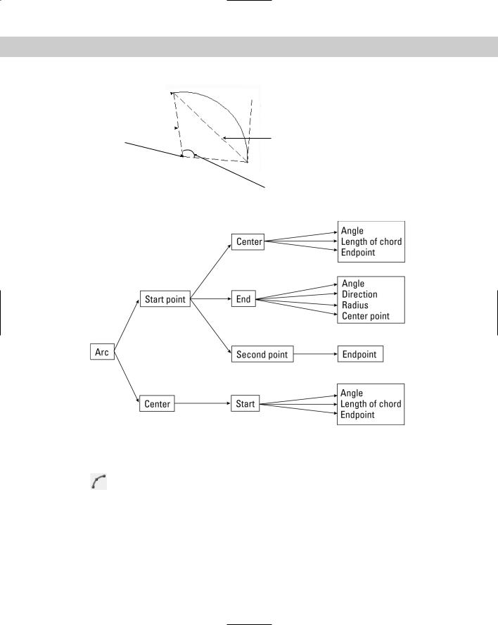
Arcs have many options. Making sense of them may seem overwhelming, but after you understand the parts of an arc, you can choose the options that suit your needs. Figure 7-3 shows the parts of an arc that you can use to draw an arc. Refer to this figure as you read through the arc options.
Figure 7-4 shows the flow of the arc options. When you start the ARC command, you have two options, Start Point and Center. Depending on which you choose, more options become available.
You can also press Enter at the first arc prompt to draw a second arc starting from the endpoint of a previous arc, line, polyline, and so on. The new arc continues in the same direction as the end of the first arc. The only other prompt is the endpoint.
Chapter 7 Drawing Curves and Points 111
Endpoint 
 Direction
Radius 
Center |
Length of chord |
 Start point
Included angle
Figure 7-3: The parts of an arc.
Figure 7-4: The ARC command options.
Drawing arcs
To draw an arc, choose Arc from the Draw toolbar and follow the prompts. As with circles, object snaps are often helpful when drawing arcs.
When drawing an arc by using the Start, End, and Radius options, the three specifications actually define two possible arcs, one minor and one major. The ARC command draws the minor arc by default, in the counterclockwise direction. (A minor arc is less than half a circle.) If you enter a negative number for the radius, the command draws the major arc (which is more than half a circle). The options requiring an angle also define two possible arcs, one drawn counterclockwise and one drawn clockwise. AutoCAD and AutoCAD LT draw the counterclockwise arc by default. If you type a negative number for the angle, the arc is drawn clockwise.
112 Part II Drawing in Two Dimensions
On the |
The drawing used in the following Step-by-Step exercise on drawing arcs, ab07-b.dwg, is in |
CD-ROM |
the Drawings folder on the CD-ROM. |
STEP-BY-STEP: Drawing Arcs
1.Open ab07-b.dwg from the CD-ROM.
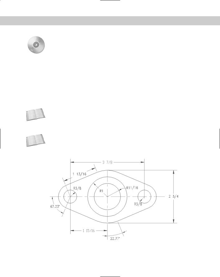
2.Save the file as ab07-02.dwg in your AutoCAD Bible folder. ORTHO is on and units are set to Fractional. Choose Tools Drafting Settings (clicking the Object Snap tab, if necessary) and set running object snaps for intersection, center, and endpoint. Make sure OSNAP is on. In this exercise, you draw part of the sealing plate shown in Figure 7-5.
3.For a change of pace, start the LINE command by choosing Line from the Command Tools tab of the tool palette. (Press Ctrl+3 to open the tool palette.) Start at 2,3 and use Direct Distance Entry to create a 7-unit horizontal line to the right. End the LINE command.
Cross- |
See Chapter 4 for a full explanation of how to use Direct Distance Entry. |
Reference |
|
4.Draw another line starting at 5-1/2,1-5/8 and draw it 2-3/4 units long in the 90-degree direction. These two lines are center lines and would ordinarily appear in a different color and linetype than the object you’re drawing.
Cross- |
You can read about colors and linetypes in Chapter 11. |
Reference |
|
5.Draw a circle with its center at the intersection of the two lines (use the Intersection object snap) and a radius of 11⁄16.
Figure 7-5: The dimensioned sealing plate for a valve.
Thanks to Jerry Bottenfield of Clow Valve Company in Oskaloosa, Iowa, for this drawing.

Chapter 7 Drawing Curves and Points 113
6.Use the Center object snap to draw another circle with the same center as the first circle and a radius of 1.
7.Draw a third circle, using the From object snap (Shift+right-click to open the object snap menu, and then choose From). For the base point, use the Center object snap and pick either of the first two circles you drew. The offset is @-1-15/16,0 (this means 1-15/16 units to the left of the center of the first two circles). Its radius is 3⁄8.
8.Draw a fourth circle. Use the From object snap again. For the base point, use the Center object snap and pick either of the first two circles. The offset is @1-15/16,0. The radius is 3⁄8.
9. Choose Arc from the Draw toolbar. Follow the prompts:
Specify start point of arc or [Center]: Choose the From object snap.
Base point: Use the Center object snap to pick the center of the
leftmost circle.
<Offset>: @-5/8,0
Specify second point of arc or [Center/End]: Right-click and choose Center. Use the Center object snap to pick the center of the leftmost circle.
Specify end point of arc or [Angle/chord Length]: Right-click and
choose Angle.
Specify included angle: 67.23
10.Start the LINE command. At the Specify first point: prompt, press Enter to con-
tinue the line in the same direction as the end of the arc. At the Length of line: prompt, type 1-13/16 . End the LINE command.
11.Choose Arc from the Draw toolbar. Follow the prompts:
Specify start point of arc or [Center]: Use the Endpoint object snap to pick the end of the line you just drew.
Specify second point of arc or [Center/End]: Right-click and choose Center. Use the Center object snap and pick any point on one of the large central circles.
Specify end point of arc or [Angle/chord Length]: Use Endpoint object snap to pick the lower end of the vertical construction line.
12.Repeat the ARC command. Follow the prompts:
Specify start point of arc or [Center]: Right-click and choose Center. Use the Center object snap and pick any point on one of the large central circles.
Specify start point of arc: Use the Endpoint object snap to pick the endpoint of the arc you just completed.
Specify end point of arc or [Angle/chord Length]: Right-click and
choose Angle.
Specify included angle: 22.77
13.Start the LINE command. At the Specify first point: prompt, press Enter to con-
tinue the line in the same direction as the end of the arc. At the Length of line: prompt, type 1-13/16 . End the LINE command.