


Editing Your
Drawing:
Basic Tools
No drawing project is ever completed without changes. You make changes in a drawing for many reasons. Some editing processes
are simply part of the drawing process, such as copying an object instead of drawing it a second time from scratch. Other types of editing involve making changes to many objects at once, such as moving an entire section of a drawing to make room for newer added objects. You often need to erase, move, rotate, and resize objects.
Without knowing how to edit, working on a drawing would become repetitive. To avoid drawing the same object a second time, you draw an object once and then copy it to a new location.
Editing a Drawing
Making changes to a drawing is called editing. In order to edit an object, you need to select it. AutoCAD and AutoCAD LT offer numerous techniques for selecting objects. In this chapter, I cover basic editing commands as well as most of the ways to select objects. The rest of the 2D editing commands, as well as additional selection and editing methods — grips, the Properties palette, selection filters, and groups — are covered in the next chapter.
Most of the editing commands are on the Modify toolbar. In most cases, you can do one of the following:
Start the command first and then select the objects to which the command applies.
Select the objects first and then start the command.
The question of which comes first, the command or the object, is fully covered later in this chapter.
Understanding object-selection basics
C 9H A P T E R
In This Chapter
Erasing objects
Copying and moving objects
Rotating objects
Scaling objects
Selecting objects
Customizing objectselection features
When you start editing drawings, the main new skill to learn is how to select objects. The selection options are covered later in this chapter.
156 Part II Drawing in Two Dimensions
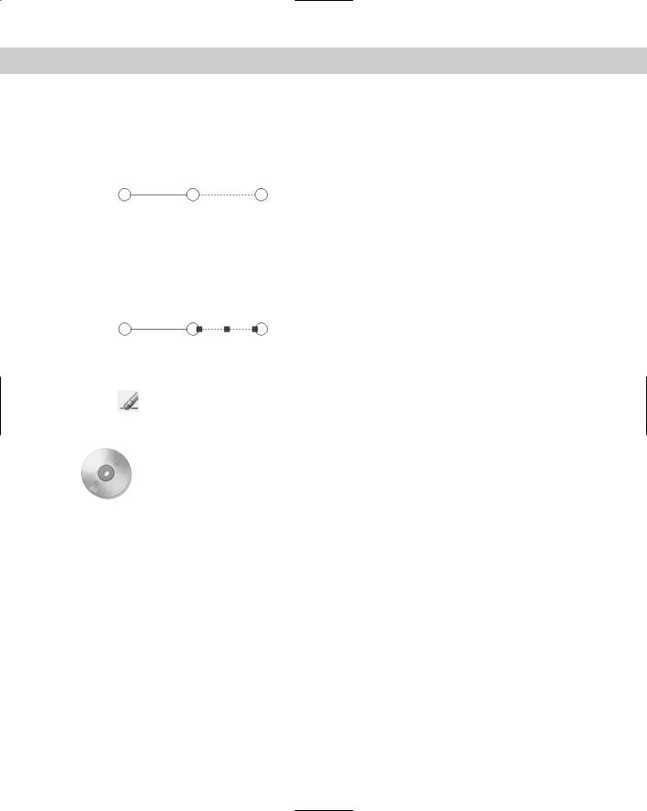
The simplest selection technique is to place the pickbox — the box at the intersection of the crosshairs — over the object and click with the pick button on the mouse. This is known as picking an object. If you start an editing command before selecting an object, the command responds with the Select objects: prompt. When you pick an object, AutoCAD or AutoCAD LT highlights it, usually by making it dashed, as shown in Figure 9-1.
Figure 9-1: The selected line is dashed.
The command continues to provide Select objects: prompts so that you can select other objects. Continue to select objects until you have selected all the objects that you want to edit. Then press Enter or right-click to end the Select objects: prompt.
When you select an object first, the selected object becomes dashed and you also see one or more small boxes, called grips, as shown in Figure 9-2. The next chapter covers grips. In the next few exercises, you use this picking technique to select objects.
Figure 9-2: The selected line is dashed and also displays grips.
Erasing objects
Somehow, no drawing is ever completed without erasing an object. The ERASE command is very simple — it has no options. To erase an object, select the object and choose Erase on the Modify toolbar or press Del on the keyboard. Alternatively, choose Erase and then select
the object.
On the |
The drawing used in the following Step-by-Step exercise on erasing objects, ab09-a.dwg, is |
CD-ROM |
in the Drawings folder on the CD-ROM. |
STEP-BY-STEP: Erasing Objects
1.Open ab09-a.dwg from the CD-ROM.
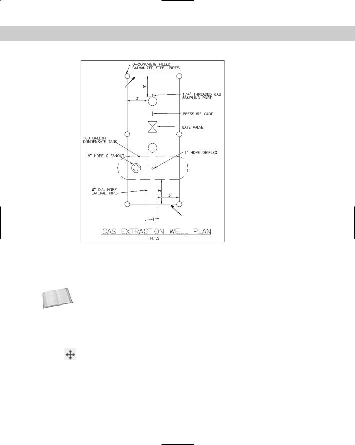
2.Save the file as ab09-01.dwg in your AutoCAD Bible folder. This drawing is a schematic of a gas extraction well, shown in Figure 9-3.
3.To erase the line at point 1 of Figure 9-3, move the mouse until the pickbox at the intersection of the crosshairs is anywhere over the line and click. Notice that the line is dashed and displays grips.
4. Choose Erase from the Modify toolbar. The line is erased.
5.Right-click and choose Repeat Erase.
6.At the Select objects: prompt, pick the line at point 2 in Figure 9-3.
7.The command responds with 1 found and repeats the Select objects: prompt. Right-click to end the Select objects: prompt. The line is erased.
Chapter 9 Editing Your Drawing: Basic Tools |
157 |
2
|
1 |
|
Figure 9-3: The gas extraction well schematic. |
|
Thanks to the Army Corps of Engineers for this drawing. The COE |
|
maintains a Web site of drawings at http://cadlib.wes.army.mil. |
|
8. Save your drawing. |
Cross- |
The OOPS command restores the most recently erased object and is covered in Chapter 18. |
Reference |
|
Moving objects
Use the MOVE command to move objects in your drawing. Moving an object is more complex than erasing one because you need to tell AutoCAD or AutoCAD LT the distance and direction that you want the object to move.
To move an object, select it and choose Move on the Modify toolbar. Alternatively, choose Move and then select the object.
When you choose the MOVE command and after you have selected an object, the command responds with the following prompt:
Specify base point or displacement:

158 Part II Drawing in Two Dimensions
You now have two ways of specifying how to move the object or objects:
Displacement method: At the Specify base point or displacement: prompt, state the entire displacement as an X,Y coordinate such as 2,3 or a polar coordinate such as 2<60. Because the word displacement already implies the relative distance from the object, you do not use @. (This method actually uses 0,0 as the relative point.) The command responds with the Specify second point of displacement or <use first point as displacement>: prompt. Because you’ve already specified all the necessary information, press Enter. AutoCAD or AutoCAD LT uses the first point you indicated as the displacement (the default) and moves the object.
Base point/second point method: At the Specify base point or displacement: prompt, pick a base point. This can be anywhere in your drawing. At the Specify second point of displacement or <use first point as displacement>: prompt, specify the distance and angle of movement either by picking a second point on the screen or by typing a relative coordinate by using @.
|
The displacement method requires less input and is simpler when you know the exact dis- |
|
placement so that you can type it in. The only disadvantage is that, as soon as you type in the |
|
displacement, you sometimes see a confusing drag line and copy of your object or objects. |
|
Ignore this display, press Enter, and your object or objects move as you specified. |
|
The base point/second point method works best when you want to move an object relative to |
|
another object on the screen. |
Tip |
When you move an object, choose an object snap on the object or a nearby-related object as |
|
the base point for exact results. |
|
You can use PolarSnap to move an object. Turn on PolarSnap and, if necessary, use the |
|
Drafting Settings dialog box to set the increment. You can set the polar distance; if the polar |
|
distance is 0. AutoCAD and AutoCAD LT use the Snap X spacing value. Use PolarSnap with the |
|
base point/second point method. At the first prompt, pick a point such as an object snap on |
|
the object. At the second prompt, drag the object in the desired direction. Use the tooltip to |
|
guide you and then click. |
|
You can use object drag-and-drop to move objects if you aren’t too particular about where |
|
they end up. Here’s how it works: |
1.Pick an object.
2.Continue to pick as many objects as you want to move. They all show grips.
3.Pick any of the objects, but not on a grip. Keep the mouse button pressed until the cursor changes to an arrow with a small rectangle.
4.Drag the object(s) to any other location in your drawing.
For a little more control over the placement of your objects, use the Windows Clipboard. Pick the object(s) that you want to move. Right-click and choose Cut from the shortcut menu. Rightclick a second time and choose Paste. At the prompt for an insertion point, you can pick with an object snap or by typing coordinates. However, you can’t control the base point (which is 0,0) as you can with the MOVE command.
On the |
The drawing used in the following Step-by-Step exercise on moving objects, ab09-b.dwg, is |
CD-ROM |
in the Drawings folder on the CD-ROM. |
Chapter 9 Editing Your Drawing: Basic Tools |
159 |
STEP-BY-STEP: Moving Objects
1.Open ab09-b.dwg from the CD-ROM.
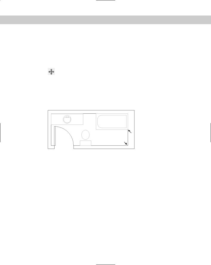
2.Save the file as ab09-02.dwg in your AutoCAD Bible folder. This drawing shows the plan of a bathroom. Each object is a block, a set of objects that you can select as one object. (Chapter 18 covers blocks.) Make sure that OSNAP is turned on. Set a running object snap for intersection only.
3.Pick anywhere on the tub to select it. Notice the grip and dashed lines. Choose Move on the Modify toolbar. Follow the prompts:
Specify base point or displacement: Move the cursor to the Intersection at 1 in Figure 9-4 and click.
Specify second point of displacement or <use first point as displacement>: Move the cursor to the Intersection at 2 in Figure 9-4 and click.
The tub moves to the bottom-right corner of the bathroom.
1
2
Figure 9-4: The bathroom plan.
Thanks to Bill Wynn of New Windsor, Maryland, for this drawing.
4.Choose Move on the Modify toolbar. Follow the prompts:
Select objects: Pick the sink.
Select objects: Specify base point or displacement: 4'<0
Specify second point of displacement or <use first point as displacement>:
The sink moves 4 feet to the right.
5.Click SNAP on the status bar to turn it on. Now, right-click SNAP. Choose PolarSnap On (unless it is already on, in which case it is unavailable). Click POLAR on the status bar.
6.Pick the toilet and choose Move on the Modify toolbar. At the Specify base point or displacement: prompt, pick the intersection at the bottom-left corner of the toilet
tank. At the Specify second point of displacement or <use first point as displacement>: prompt, move the toilet to the left until you see 0’-6”<180° on the tooltip and click. The toilet moves 6 inches to the left. (If you can’t get a 180° tooltip, check your polar angle settings.)
7.Save your drawing.
160 Part II Drawing in Two Dimensions
Copying objects
Copying is very similar to moving. In fact, the only difference is that AutoCAD or AutoCAD LT does not remove the object from its original spot, so you end up with two objects instead
of one.
To copy an object, select it and choose Copy Object on the Modify toolbar. Alternatively, choose Copy Object and then select the object.
New
Feature
The COPY command now defaults to continue to prompt you for additional copies. This default is equivalent to the previous Multiple option. Press Enter whenever you want to end the command. However, scripts and other routines use the earlier functioning, in which the command ended after creating one copy.
When you choose the COPY command and have selected an object, the command responds with the following prompt:
Specify base point or displacement:
You now have two ways of specifying where to copy the object or objects:
Displacement method: At the Specify base point or displacement: prompt, state the entire displacement as an X,Y coordinate such as 2,3 or a polar coordinate such as 2<60. Because the word displacement already implies the relative distance from the object, you do not use @. (This method actually uses 0,0 as the relative point.) The command responds with the Specify second point of displacement or <use first point as displacement>: prompt. Because you’ve already specified all the necessary information, press Enter. The command uses the first point you indicated as the displacement (the default) and copies the object.
Base point/second point method: At the Specify base point or displacement: prompt, pick a base point. This can be anywhere in your drawing. At the Specify second point of displacement or <use first point as displacement>: prompt, specify the distance and angle of movement either by picking a second point on the screen or by typing in a relative coordinate, using @.
As explained in the previous section on moving objects, you can use PolarSnap to copy objects.
You can also use drag-and-drop to copy objects. Follow the steps in the previous section, but press and hold the Ctrl key as you drag the object. Notice the plus sign in the cursor’s rectangle. In the same way, you can use the Clipboard to copy and paste objects from one location in a drawing to another.
On the |
The drawing used in the following Step-by-Step exercise on copying objects, ab09-c.dwg, is |
CD-ROM |
in the Drawings folder on the CD-ROM. |
STEP-BY-STEP: Copying Objects
1.Open ab09-c.dwg from the CD-ROM.
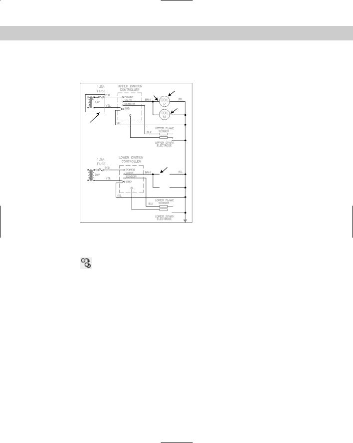
2.Save the file as ab09-03.dwg in your AutoCAD Bible folder. This drawing shows part of an electrical schematic. Make sure that OSNAP is turned on. Set a running object snap for endpoint only.
Chapter 9 Editing Your Drawing: Basic Tools |
161 |
3.Use ZOOM Window to zoom into the area of the drawing marked 1 in Figure 9-5. This shows a 24-volt transformer.
2
4
3
1
5
Figure 9-5: The electrical schematic.
Thanks to Robert Mack of the Dexter Company, Fairfield,
Iowa, for this drawing.
4.Note that three of the arcs that make up the right side of the transformer are miss-
ing. Pick the arc at 1 in Figure 9-6. Choose Copy Object from the Modify toolbar. Follow the prompts:
Specify base point or displacement: Pick the endpoint at the top of
the arc at 2 (see Figure 9-6). |
|
|
Specify second point of |
displacement or |
<use first point as |
displacement>: Pick the |
endpoint at the |
bottom of the first arc at 3 |
(see Figure 9-6). |
|
|
Specify second point of |
displacement or |
<use first point as |
displacement>: Pick the |
endpoint at the |
bottom of the second arc at |
4 (see Figure 9-6). |
|
|
Specify second point of |
displacement or |
<use first point as |
displacement>: Pick the |
endpoint at the |
bottom of the third arc at 5 |
(see Figure 9-6). |
|
|
Specify second point of |
displacement or |
<use first point as |
displacement>: |
|
|
5. Choose ZOOM Previous from the Standard toolbar to return to your previous view.

162 Part II Drawing in Two Dimensions
2
1
3
4
5
Figure 9-6: Close-up of the transformer.
6.Pick the circle at 2 in Figure 9-5 (which shows the entire schematic section). Note the grips. You also want to select the text inside the circles, but it’s hard to see because of the grips. Press Esc to remove the grips.
7.Choose Copy Object from the Modify toolbar. Now select the circle at 2 in Figure 9-5 again. This time no grips obscure the text. Separately pick both lines of text inside the circle.
8.Continuing to select objects to copy, select the circle at 3 in Figure 9-5. Also select the two lines of text inside the circle. Right-click to end the Select objects: prompt.
9.At the Specify base point or displacement: prompt, use the Endpoint object snap to pick point 4 in Figure 9-5. At the Specify second point of displacement or <use first point as displacement>: prompt, use the Endpoint object snap to pick point 5 in Figure 9-5. Press Enter to end the COPY command. This action copies the two circles with the text.
10.Save your drawing.
Copying and moving objects from one drawing to another
If you use other Windows programs, you usually use the Cut command to move and the Copy command to copy objects. Then you use the Paste command to specify a new location. In AutoCAD and AutoCAD LT, these commands are called CUTCLIP, COPYCLIP, and PASTECLIP. (The CLIP refers to the Windows Clipboard.) Although the MOVE and COPY commands provide more accuracy within one drawing, you can use the Clipboard to move and copy objects from one drawing to another.
You can copy objects from one drawing to another by using the drag-and-drop technique. The easiest way is to open both drawings and then choose Window Tile Vertically. Select the object(s) that you want to copy, point to one of them, and drag to the second drawing. However, you don’t have much control over the exact placement of the new objects. From drawing to drawing, AutoCAD or AutoCAD LT copies the objects, instead of moving them.

Chapter 9 Editing Your Drawing: Basic Tools |
163 |
For more control over the placement of your objects, use the Windows Clipboard. A special feature, Copy with Base Point, gives you control over the placement of your objects. Follow these steps:
1.Pick the object(s) that you want to copy.
2.Right-click and choose Copy with Base Point from the shortcut menu.
3.At the Specify base point: prompt, specify a base point. An object snap is a good idea here. This action copies the object(s) to the Clipboard, including the base point.
4.Switch to the second drawing.
5.Right-click in the drawing area and choose Paste (or click Paste on the Standard toolbar). At the prompt for an insertion point, specify the insertion point by picking, using an object snap, or typing coordinates. This action pastes the object.
To copy the object(s) to the same coordinates as the original drawing, in Step 5 choose Paste to Original Coordinates from the shortcut menu. AutoCAD or AutoCAD LT pastes the object(s) in the second drawing, matching the coordinates. Depending on your drawing, you may need to ZOOM and PAN to see the pasted copy.
You cannot specify a base point for moving (cutting) an object, but you can specify the insertion point when you paste it. The lower-left extent of the selected object(s) is the base point.
Cross- You can drag objects from a drawing into another application, such as a word processing Reference document. For more information on working with AutoCAD or AutoCAD LT and other appli-
cations, see Chapter 27.
In the following exercise, you practice copying objects from one drawing to another.
On the |
The drawing used in the following Step-by-Step exercise on copying objects from one draw- |
CD-ROM |
ing to another, ab09-c.dwg, is in the Drawings folder on the CD-ROM. |
STEP-BY-STEP: Copying Objects from One Drawing to Another
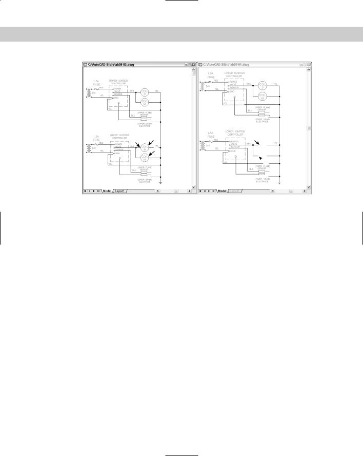
1.Close any open drawings. Open ab09-c.dwg from the CD-ROM. Save the file as ab09-04.dwg in your AutoCAD Bible folder. Then choose Open from the Standard toolbar and open ab09-03.dwg from your AutoCAD Bible folder. If you didn’t do the previous exercise, open ab09-03.dwg from the Results folder on the CD-ROM.
2.Choose Window Tile Vertically. This displays the drawings side by side, as shown in Figure 9-7.
3.In ab09-03.dwg, which should be active, make sure that OSNAP is turned on. Set a running object snap set for endpoint only.
4.Pick the circle at 1 and the two lines of text inside it.
5.Move the cursor off the selected objects and right-click. Choose Copy with Base Point from the shortcut menu.
6.At the Specify base point: prompt, pick the endpoint at 2 in Figure 9-7.
164 Part II Drawing in Two Dimensions
2 |
1 |
3 |
|
|
|
|
4 |
|
 5
5
Figure 9-7: To copy objects from one drawing to another, display them both on the screen together. (The drawings may appear reversed on your screen.)
7.Click anywhere in ab09-04.dwg to make it the current drawing. Right-click and choose Paste from the shortcut menu. At the Specify insertion point: prompt, pick the endpoint at 3 in Figure 9-7 to paste the objects.
8.Click in ab09-03.dwg. Press Esc to clear any grips. Pick the circle at 4 in Figure 9-7. (Don’t include the text this time.) Click again and hold the mouse button on the circle, but not on the grips, until you see the pointer arrow with the rectangle. Drag the circle to 5 in Figure 9-7. As you can see, you have no way to precisely place the circle.
9.Click in ab09-03.dwg again. This time pick both lines of text inside the circle at 4. Right-click and choose Copy with Base Point. At the Specify base point: prompt, pick the endpoint at the left quadrant of the circle.
10.Click in ab09-04.dwg. Right-click and choose Paste to Original Coordinates to paste the two lines of text inside the circle (depending on how accurately you dragged the circle).
11.Save ab09-04.dwg. Click in ab09-03.dwg and click its Close box. Don’t save changes to ab09-03.dwg.
Rotating objects
You can easily rotate an object or objects around a base point that you specify. The base point is usually an object snap point on the object. To indicate the rotation, specify an angle of rotation. As explained in Chapter 5, zero degrees is generally to the right, and degrees increase counterclockwise, although you can change this convention. (To do so, choose Format Units.) By specifying a negative angle, you can turn objects clockwise.
Chapter 9 Editing Your Drawing: Basic Tools |
165 |
To rotate an object, choose Rotate from the Modify toolbar and select an object. Alternatively, select an object and then choose Rotate from the Modify toolbar. At
the Specify base point: prompt, indicate the point around which you want to rotate. At the Specify rotation angle or [Reference]: prompt, type an angle at the command line.
The Reference option lets you specify an absolute existing rotation angle and the desired angle. At the Specify the reference angle <0>: prompt, you type in an angle or specify an angle by picking two points. These can be object snap points on the object that specify the object’s current angle. At the Specify the new angle: prompt, type or pick a new angle. You can also pick an object snap on another object in the drawing to indicate this new angle. You can use the Reference option to align the object with the X or Y axis or with another object in your drawing.
On the |
The drawing used in the following Step-by-Step exercise on rotating objects, ab07-03.dwg, |
CD-ROM |
is in the Results folder on the CD-ROM. |
STEP-BY-STEP: Rotating Objects
1.Open ab07-03.dwg from the Results folder of the CD-ROM. If you did the Step-by-Step exercise on ellipses in Chapter 7, you can open this drawing from your AutoCAD Bible folder.
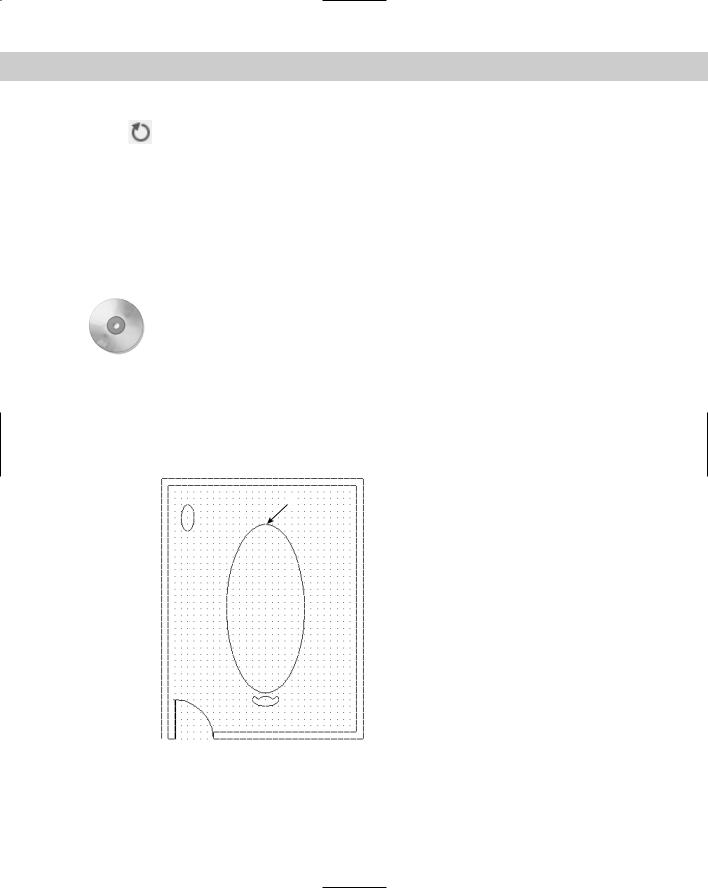
2.Save the file as ab09-05.dwg in your AutoCAD Bible folder. This drawing shows a conference room, as shown in Figure 9-8.
1
Figure 9-8: The conference room.

166 Part II Drawing in Two Dimensions
3.Click GRID on the status bar to remove the grid.
4.Choose Tools Drafting Settings. On the Object Snap tab, choose Center, Quadrant, and Perpendicular. Click OK. OSNAP should be on.
5.Pick the small elliptical table at the top-left corner of the conference room. Choose Rotate from the Modify toolbar.
6.At the Specify base point: prompt, pick the top quadrant of the ellipse. At the
Specify rotation angle or [Reference]: prompt, type 90 . This action rotates the small table 90 degrees around the base point.
7.Click SNAP on the status bar to turn off snap.
8.Start the COPY command. At the Select objects: prompt, pick the arc that makes the back of the chair. The command responds 1 found. Continue to pick the two lines that make the armrests and the arc that makes the front of the chair, making sure that each time you see the response 1 found. Right-click to end the Select objects: prompt.
9.At the Specify base point or displacement: prompt, locate the Center object snap to pick the center of the arc that makes up the back of the chair. (Press Tab to cycle through the object snaps if necessary or move the cursor over the arc itself, or
its center.) At the Specify second point of displacement or <use first point as displacement>: prompt, pick point 1 in Figure 9-8. This point doesn’t have to be exact. Press Enter to end the command.
10.Start the ROTATE command. Follow the prompts:
Select objects: Pick all four objects that make up the new chair you just created and press Enter to end object selection.
Specify base point: Use the Center object snap to select the center
of the arc that makes up the back of the new chair.
Specify rotation angle or [Reference]: 180 .
11.Start the COPY command and select the four objects in the new chair. Right-click to end object selection. Follow the prompts:
Specify base point or displacement: Use the Center object snap to select the center of the arc that makes up the back of the chair.
Specify second point of displacement or <use first point as displacement>: Pick a point about a third of the way around the right side of the conference table.
Specify second point of displacement or <use first point as displacement>: Pick a point about halfway around the right side of the conference table.
Specify second point of displacement or <use first point as displacement>: Pick a point about two-thirds of the way around the right side of the conference table.
Specify second point of displacement or <use first point as displacement>:

Chapter 9 Editing Your Drawing: Basic Tools |
167 |
12.Start the ROTATE command and select the four objects in the first of the three chairs (the top one) you just created. Right-click to end object selection. (If Polar Tracking or Object Snap is on, turn them off for better control.) At the Specify base point: prompt, pick the center object snap of either arc of the chair. At the
Specify rotation angle or [Reference]: prompt, move the cursor around, watch the image of the chair rotate, and click when the chair faces the angle of the table.
13.Repeat Step 12 for the second chair.
14.Start the ROTATE command and select the four objects in the last chair you created by using the COPY command. Follow the prompts:
Specify base point: Choose the Center object snap of either of the chair arcs.
Specify rotation angle or [Reference]: Right-click and choose Reference from the shortcut menu.
Specify the reference angle <0>: Use the Quadrant object snap to pick the back arc of the chair.
Specify second point: Use the Quadrant object snap to pick the front arc of the chair.
Specify the new angle: Use the Perpendicular object snap to choose the conference table next to the chair.
15.Save your drawing.
Scaling objects
Scaling, or resizing, objects is another common editing task in AutoCAD or AutoCAD LT. As with rotating objects, you specify a base point, usually an object snap on the object. The base point is the one point on the object that does not move or change as you scale the object. The most common way to resize an object is to specify a scale factor. The current object has a scale factor of 1. Therefore, to increase the size of the object, type in a number greater than 1. For example, a scale factor of 2 doubles the size of the object. To decrease the size of the object, type in a number less than 1. A scale factor of 0.25 creates an object one-quarter of its previous size.
As with the ROTATE command, you can scale by using the Reference option. You specify the reference length, usually the current length of the object, by typing it in or using object snaps on the object. At the Specify new length: prompt, you can type a new length or pick a point. The option measures this point from the base point you specified to determine the new length.
To scale an object, choose Scale from the Modify toolbar and select the object. Alternatively, select the object and choose Scale from the Modify toolbar.
On the |
The drawing used in the following Step-by-Step exercise on scaling objects, ab09-d.dwg, is |
CD-ROM |
in the Drawings folder on the CD-ROM. |
168 Part II Drawing in Two Dimensions
STEP-BY-STEP: Scaling Objects
1.Open ab09-d.dwg from the CD-ROM.
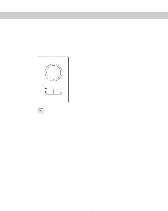
2.Save the file as ab09-06.dwg in your AutoCAD Bible folder. This drawing, shown in Figure 9-9, shows part of a valve that is manufactured in several sizes. In this exercise, you scale both views to represent a different-size valve piece. Ensure OSNAP is on. Set running object snaps for quadrant and endpoint.
Figure 9-9: The valve piece in two views.
Thanks to Jerry Bottenfield of Clow Valve Company,
Oskaloosa, Iowa, for this drawing.
1
3.Choose Scale from the Modify toolbar. At the Select objects: prompt, pick
both circles in the top view (they’re actually arcs because they’re broken at the bottom) and the two short lines at the bottom of the circles. Press Enter to end object selection. Follow the prompts:
Specify base point: Use the Quadrant object snap to pick the left quadrant of the inner circle.
Specify scale factor or [Reference]: Right-click and choose Reference.
Specify reference length <1>: Use the Quadrant object snap to pick the left quadrant of the inner circle again.
Specify second point: Use the Quadrant object snap to pick the right quadrant of the inner circle.
Specify new length: 1
Because the distance between the two quadrants you chose is 2.5 units, the SCALE command scales the objects to 40 percent (1 divided by 2.5).
4.Right-click and choose Repeat Scale. Select all eight lines in the bottom view including the green dashed lines. Be sure that you see 1 found each time. If necessary, use ZOOM Window to zoom in. Right-click to end object selection after you finish selecting the lines. Follow the prompts:
Specify base point: Use the Endpoint object snap at point 1 in
Figure 9-9.
Specify scale factor or [Reference]: .4
5.Save your drawing. It should look like Figure 9-10.

Chapter 9 Editing Your Drawing: Basic Tools |
169 |
Figure 9-10: The valve piece has now been scaled down.
Using the CHANGE command
The CHANGE command changes the endpoint of a line and the radius of a circle. This command can also be used to change text (see Chapter 13) and the location of blocks (covered in Chapter 18), but other newer commands do the job better. You can also use grips and the Properties palette, both covered in the next chapter, to change line endpoints and circle radii (among other object properties).
To change an object, select it and type change on the command line. Alternatively, type change on the command line and select the object.
Caution |
The CHANGE command works differently depending on whether you select lines or circles. |
|
For this reason, it can give unexpected results if you choose lines and circles at the same time. |
|
Use the command for either lines or circles but not for both at once. |
Changing lines
If you select one line, the CHANGE command changes the endpoint closest to where you picked the line. The command prompts you for a change point. When you pick the point, the command brings the endpoint of the line to that change point, as shown in Figure 9-11. You can use an object snap to specify the change point. If ORTHO is on, the line becomes orthogonal, bringing the endpoint of the line as close as possible to the change point you specify, as shown in Figure 9-11.
Original line
 Change point
 New line with ORTHO off
 New line with ORTHO on
Figure 9-11: Using the CHANGE command on one line.