

- •Foreword
- •Preface
- •Is This Book for You?
- •How This Book Is Organized
- •How to Use This Book
- •Doing the Exercises
- •Conventions Used in This Book
- •What the Icons Mean
- •About the CD-ROM
- •Other Information
- •Contacting the Author
- •Acknowledgments
- •Contents at a Glance
- •Contents
- •Getting Acquainted with AutoCAD and AutoCAD LT
- •Starting AutoCAD and AutoCAD LT
- •Creating a New Drawing
- •Using the AutoCAD and AutoCAD LT Interface
- •Creating Your First Drawing
- •Saving a Drawing
- •Summary
- •Creating a New Drawing from a Template
- •Working with Templates
- •Opening a Drawing with Default Settings
- •Opening an Existing Drawing
- •Using an Existing Drawing as a Prototype
- •Saving a Drawing Under a New Name
- •Summary
- •The Command Line
- •Command Techniques
- •Of Mice and Pucks
- •Getting Help
- •Summary
- •Typing Coordinates
- •Displaying Coordinates
- •Picking Coordinates on the Screen
- •Locating Points
- •Summary
- •Unit Types
- •Drawing Limits
- •Understanding Scales
- •Inserting a Title Block
- •Common Setup Options
- •The MVSETUP Command
- •Summary
- •Using the LINE Command
- •Drawing Rectangles
- •Drawing Polygons
- •Creating Construction Lines
- •Creating Rays
- •Summary
- •Drawing Circles
- •Drawing Arcs
- •Creating Ellipses and Elliptical Arcs
- •Making Donuts
- •Placing Points
- •Summary
- •Panning
- •The ZOOM Command
- •Aerial View
- •Named Views
- •Tiled Viewports
- •Snap Rotation
- •User Coordinate Systems
- •Isometric Drawing
- •Summary
- •Editing a Drawing
- •Selecting Objects
- •Summary
- •Copying and Moving Objects
- •Using Construction Commands
- •Creating a Revision Cloud
- •Hiding Objects with a Wipeout
- •Double-Clicking to Edit Objects
- •Grips
- •Editing with the Properties Palette
- •Selection Filters
- •Groups
- •Summary
- •Working with Layers
- •Changing Object Color, Linetype, and Lineweight
- •Working with Linetype Scales
- •Importing Layers and Linetypes from Other Drawings
- •Matching Properties
- •Summary
- •Drawing-Level Information
- •Object-Level Information
- •Measurement Commands
- •AutoCAD’s Calculator
- •Summary
- •Creating Single-Line Text
- •Understanding Text Styles
- •Creating Multiline Text
- •Creating Tables
- •Inserting Fields
- •Managing Text
- •Finding Text in Your Drawing
- •Checking Your Spelling
- •Summary
- •Working with Dimensions
- •Drawing Linear Dimensions
- •Drawing Aligned Dimensions
- •Creating Baseline and Continued Dimensions
- •Dimensioning Arcs and Circles
- •Dimensioning Angles
- •Creating Ordinate Dimensions
- •Drawing Leaders
- •Using Quick Dimension
- •Editing Dimensions
- •Summary
- •Understanding Dimension Styles
- •Defining a New Dimension Style
- •Changing Dimension Styles
- •Creating Geometric Tolerances
- •Summary
- •Creating and Editing Polylines
- •Drawing and Editing Splines
- •Creating Regions
- •Creating Boundaries
- •Creating Hatches
- •Creating and Editing Multilines
- •Creating Dlines
- •Using the SKETCH Command
- •Digitizing Drawings with the TABLET Command
- •Summary
- •Preparing a Drawing for Plotting or Printing
- •Creating a Layout in Paper Space
- •Working with Plot Styles
- •Plotting a Drawing
- •Summary
- •Combining Objects into Blocks
- •Inserting Blocks and Files into Drawings
- •Managing Blocks
- •Using Windows Features
- •Working with Attributes
- •Summary
- •Understanding External References
- •Editing an Xref within Your Drawing
- •Controlling Xref Display
- •Managing Xrefs
- •Summary
- •Preparing for Database Connectivity
- •Connecting to Your Database
- •Linking Data to Drawing Objects
- •Creating Labels
- •Querying with the Query Editor
- •Working with Query Files
- •Summary
- •Working with 3D Coordinates
- •Using Elevation and Thickness
- •Working with the User Coordinate System
- •Summary
- •Working with the Standard Viewpoints
- •Using DDVPOINT
- •Working with the Tripod and Compass
- •Getting a Quick Plan View
- •Shading Your Drawing
- •Using 3D Orbit
- •Using Tiled Viewports
- •Defining a Perspective View
- •Laying Out 3D Drawings
- •Summary
- •Drawing Surfaces with 3DFACE
- •Drawing Surfaces with PFACE
- •Creating Polygon Meshes with 3DMESH
- •Drawing Standard 3D Shapes
- •Drawing a Revolved Surface
- •Drawing an Extruded Surface
- •Drawing Ruled Surfaces
- •Drawing Edge Surfaces
- •Summary
- •Drawing Standard Shapes
- •Creating Extruded Solids
- •Drawing Revolved Solids
- •Creating Complex Solids
- •Sectioning and Slicing Solids
- •Using Editing Commands in 3D
- •Editing Solids
- •Listing Solid Properties
- •Summary
- •Understanding Rendering
- •Creating Lights
- •Creating Scenes
- •Working with Materials
- •Using Backgrounds
- •Doing the Final Render
- •Summary
- •Accessing Drawing Components with the DesignCenter
- •Accessing Drawing Content with Tool Palettes
- •Setting Standards for Drawings
- •Organizing Your Drawings
- •Working with Sheet Sets
- •Maintaining Security
- •Keeping Track of Referenced Files
- •Handling Errors and Crashes
- •Managing Drawings from Prior Releases
- •Summary
- •Importing and Exporting Other File Formats
- •Working with Raster Images
- •Pasting, Linking, and Embedding Objects
- •Summary
- •Sending Drawings
- •Opening Drawings from the Web
- •Creating Object Hyperlinks
- •Publishing Drawings
- •Summary
- •Working with Customizable Files
- •Creating Keyboard Shortcuts for Commands
- •Customizing Toolbars
- •Customizing Tool Palettes
- •Summary
- •Creating Macros with Script Files
- •Creating Slide Shows
- •Creating Slide Libraries
- •Summary
- •Creating Linetypes
- •Creating Hatch Patterns
- •Summary
- •Creating Shapes
- •Creating Fonts
- •Summary
- •Working with Menu Files
- •Customizing a Menu
- •Summary
- •Introducing Visual LISP
- •Getting Help in Visual LISP
- •Working with AutoLISP Expressions
- •Using AutoLISP on the Command Line
- •Creating AutoLISP Files
- •Summary
- •Creating Variables
- •Working with AutoCAD Commands
- •Working with Lists
- •Setting Conditions
- •Managing Drawing Objects
- •Getting Input from the User
- •Putting on the Finishing Touches
- •Summary
- •Understanding Local and Global Variables
- •Working with Visual LISP ActiveX Functions
- •Debugging Code
- •Summary
- •Starting to Work with VBA
- •Writing VBA Code
- •Getting User Input
- •Creating Dialog Boxes
- •Modifying Objects
- •Debugging and Trapping Errors
- •Moving to Advanced Programming
- •A Final Word
- •Installing AutoCAD and AutoCAD LT
- •Configuring AutoCAD
- •Starting AutoCAD Your Way
- •Configuring a Plotter
- •System Requirements
- •Using the CD with Microsoft Windows
- •What’s on the CD
- •Troubleshooting
- •Index
594 Part IV Drawing in Three Dimensions
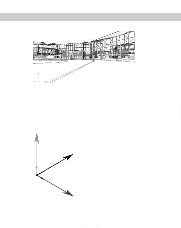
Figure 21-2: The same office building viewed from the front.
Working with 3D Coordinates
All the 2D methods of specifying coordinates have their 3D counterparts. Just as you can draw a line by specifying a start point of 3,4 and an endpoint of 5,7, you can draw a 3D line by specifying a start point of 3,4,2 and an endpoint of 5,7,6. Absolute coordinates are the same in 3D — you just add a Z coordinate. In the same way, you can specify relative coordinates. In 3D drawings, you can use two new types of coordinates that are 3D counterparts of polar coordinates — cylindrical and spherical. Figure 21-3 shows the three axes X, Y, and Z. The arrows show the positive direction of the axes.
Figure 21-3: The three axes in 3D drawing.

Chapter 21 Specifying 3D Coordinates 595
Cross- |
Working with the User Coordinate System (UCS) is essential in 3D work. If you aren’t familiar |
Reference |
with the User Coordinate System, review the discussion in Chapter 8. |
|
Most 2D commands, however, accept 3D coordinates (that is, a coordinate that includes a Z value) only on the first point. After that you must omit the Z coordinate because the Z value must be the same as that of the first point. For example, if you draw a rectangle, you can specify its first corner as 2,3,8 but the second corner must be specified without the Z value, as in 6,7. The Z value for the opposite corner is automatically 8.
The LINE command is an exception. It is a true 3D command, so you can specify X, Y, and Z values at all points.
Absolute and relative Cartesian coordinates in 3D
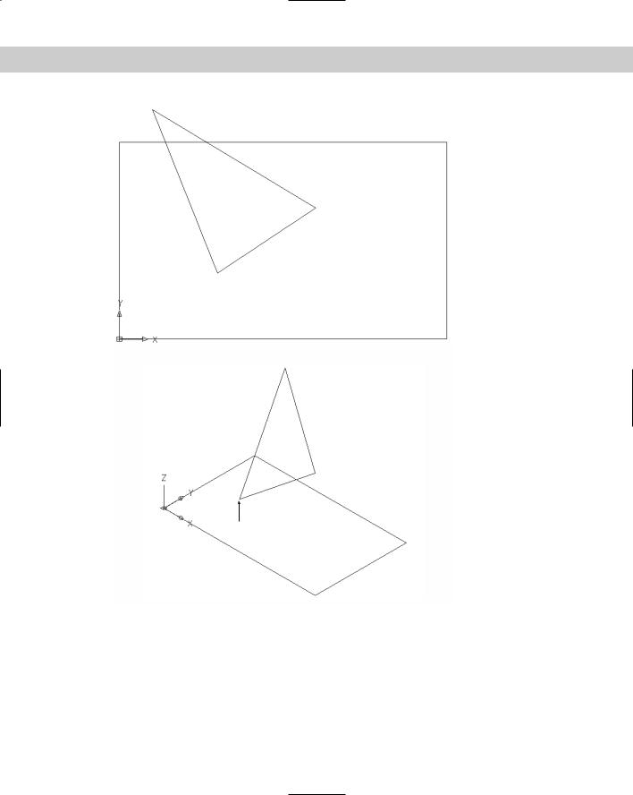
You don’t use absolute coordinates more in 3D than you do in 2D — maybe less. But understanding absolute coordinates is important to understanding the Cartesian coordinate system that defines every point in your drawing. Figure 21-4 shows a wireframe model of a square and a triangle drawn with absolute coordinates, viewed from above (plan view) and from the southeast view (above, to the right, and in front). The square is drawn in 2D — which means that the Z coordinates are all zero — to be a reference point for visualizing the 3D points of the triangle.
You can use relative coordinates in the same way by including the change in coordinates. For example, to draw the line from (3,2,1) to (6,4,3), shown in Figure 21-4, you can start with the absolute coordinate (3,2,1) and then specify @3,2,2 because that’s the difference between (3,2,1) and (6,4,3).
Cylindrical and spherical coordinates
Just as polar coordinates are often more useful than Cartesian coordinates in 2D, cylindrical and spherical coordinates can be more useful in 3D. Here’s how they work.
Cylindrical coordinates have the format (@)distance<angle,distance:
The first distance is the number of units in the XY plane from the origin (for absolute coordinates) or your last point (for relative coordinates).
The angle is the number of degrees from the X axis in the XY plane.
The second distance is the number of units along the Z axis.
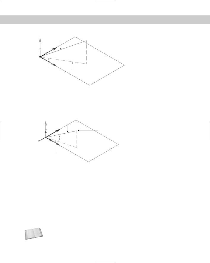
Cylindrical coordinates can be absolute or relative. Add the @ for relative coordinates. When you draw a line using cylindrical coordinates, neither distance you specify is the length of the line. In essence, you’re defining the lengths of two sides of a triangle to draw the hypotenuse. Figure 21-5 shows an example of a line drawn with cylindrical coordinates. The line was drawn from 0,0,0 to @5<30,3, which results in a line 5.8310 units long. (The @ wasn’t necessary because the line was drawn from 0,0,0.)
The two sides of the triangle are 5 and 3 units long. To calculate the length of the hypotenuse, use the Pythagorean theorem, which says that a2 + b2 = c2, where a and b are the two sides of the triangle and c is the hypotenuse. Therefore, the hypotenuse is the square root of 25 + 9 or 34, which is 5.8310. Of course, you can use the DIST or LIST command to check it out.
596 Part IV Drawing in Three Dimensions
 1,7,5
1,7,5
 6,4,3
6,4,3
0,0,0 
3,2,1
 10,6,0
Figure 21-4: A rectangle and triangle viewed from plan view and southeast view.
Spherical coordinates have the format (@)distance<angle<angle:
The first distance is the total number of units from the origin (for absolute coordinates) or your last point (for relative coordinates).
The first angle is the number of degrees from the X axis in the XY plane.
The second angle is the number of degrees from the XY plane in the Z direction.
Chapter 21 Specifying 3D Coordinates 597
5.8310 units
 @5<30,3
 3 units
30o
5 units
Figure 21-5: A line drawn using cylindrical coordinates.
Spherical coordinates can be absolute or relative. Add the @ for relative coordinates. When you draw a line using spherical coordinates, the first distance is the actual length of the line. Figure 21-6 shows an example of a line drawn with spherical coordinates. The line was drawn from 0,0,0 to @5<15<30.
5 units
@5<15<30
 30o in the Z direction
15o in the XY plane
Figure 21-6: A line drawing using spherical coordinates.
Using editing commands with 3D wireframes
Certain 2D editing commands work well in 3D. Others have special 3D versions. Because wireframes are simply 2D objects placed in 3D space, you can generally use the familiar editing commands. For example, to move an object 3 units in the positive Z-axis direction, type 0,0,3 at the Specify base point or displacement: prompt and press Enter twice.
You need to be careful when selecting objects for editing. For example, if you draw two identically sized rectangles at different Z coordinates, you see only one rectangle when you look at them from plan view. How do you know which rectangle you’re selecting? By changing the angle from which you view your drawing (fully covered in the next chapter), you can see all the parts of the drawing and can select objects easily.
Cross- Multiple tiled viewports in which you view your drawing from different viewpoints can be Reference very helpful in 3D drawing. For example, you can have a plan view in one viewport and a
southeast view in another. Tiled viewports are covered in Chapter 8.

598 Part IV Drawing in Three Dimensions
In the following exercise, you draw a simple wireframe piano bench and practice using 3D coordinates for both drawing and editing commands. You also view the drawing from two different angles.
On the |
The drawing used in the following Step-by-Step exercise on using 3D coordinates, ab21-a. |
CD-ROM |
dwg, is in the Drawings folder on the CD-ROM. |
STEP-BY-STEP: Using 3D Coordinates
1.Open ab21-a.dwg from the CD-ROM.
2.Save it as ab21-01.dwg in your AutoCAD Bible folder.
3.Choose Rectangle from the Draw toolbar. At the Specify first corner point or [Chamfer/Elevation/Fillet/Thickness/Width]: prompt, type 0,0,19 . At the Specify other corner point or [Dimensions]: prompt, type 39,15 . This creates a rectangle 39 units long by 15 units wide that is 19 units above the plane created by the X and Y axes. Notice that you omit the Z coordinate for the second corner.
4.Start the COPY command. To copy the rectangle 2 units above the original rectangle, follow the prompts:
Select objects: Pick the rectangle.
Select objects:
Specify base point or displacement, or [Multiple]: 0,0,2
Specify second point of displacement or <use first point as displacement>:
You now have two rectangles, but because you’re looking from the top, you see only one.
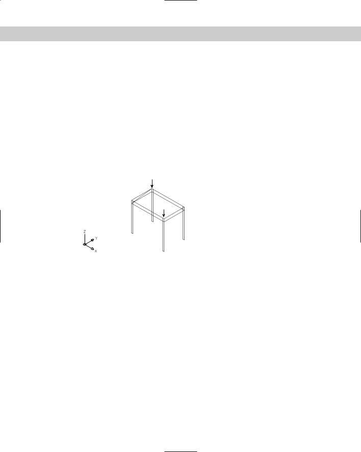
5.Choose View 3D Views SE Isometric. Now you can see the two rectangles, as shown in Figure 21-7.
1
3
4
2
Figure 21-7: The two rectangles, shown from Southeast Isometric view.

Chapter 21 Specifying 3D Coordinates 599
6.If OSNAP is not on, click it on the status bar. Set a running object snap for endpoints.
7.Start the LINE command. Follow the prompts:
Specify first point: Pick the endpoint at 1 in Figure 21-7.
Specify next point or [Undo]: 0,0,0 Specify next point or [Undo]: 1,0,0 Specify next point or [Close/Undo]: 1,0,21 Specify next point or [Close/Undo]:
8.Start the COPY command. At the Select objects: prompt, select the three lines you
just drew. End object selection. At the Specify base point or displacement, or [Multiple]: prompt, type 38,0,0 . At the Specify second point of displacement or <use first point as displacement>: prompt, press Enter to copy the three lines. Because the bench is 39 units long and the legs are 1 unit wide, copying the leg 38 units in the X direction places the copy in the right location.
9.Do a Zoom Extents so that you can see the entire drawing.
10.Repeat the COPY command. Use two separate crossing windows to select the first leg,
then the second leg. Each window should select three objects. End object selection. At the Specify base point or displacement, or [Multiple]: prompt, type 0,15,0 to copy the legs 15 units in the Y direction. Press Enter at the Specify second point of displacement or <use first point as displacement>: prompt to copy the legs to the back of the bench.
11.To draw an open cover for the piano bench, start the LINE command. Start it at the
endpoint at 2 in Figure 21-7. At the Specify next point or [Undo]: prompt, type @15<90<45 . You know the length of the line because the cover is the same as the width of the piano bench. At the Specify next point or [Undo]: prompt, turn on ORTHO, move the cursor parallel to the length of the bench, and type 39. At the Specify next point or [Close/Undo]: prompt, use the Endpoint object snap to pick 3. End the LINE command. Zoom out and pan so you can see the entire bench.
12.To draw some bracing inside the bench, start the LINE command again. At the
Specify first point: prompt, choose the endpoint at 4. At the Specify next point or [Undo]: prompt, type @15<90,2 . End the LINE command. Here, cylindrical coordinates are ideal because you don’t know the length of the line but you know the change in the X and Z coordinates (the width and the height of the bench’s body, respectively).
13.Save your drawing. It should look like Figure 21-8.
Using point filters, object snaps, and grips in 3D
As mentioned earlier, it’s often hard to tell which point you’re picking in 3D. On a flat screen, you can only be sure of two dimensions. The other dimension is, so to speak, going in or out of the screen — it could be X, Y, or Z depending on the angle you’re using to look at the drawing. That dimension is the one that’s hard to pick on the screen. You use point filters, object snaps, and grips to be sure you have the right point in 3D drawings.
600 Part IV Drawing in Three Dimensions
Figure 21-8: The completed wireframe piano bench.
Point filters
In Chapter 4, I discuss point filters for 2D objects. They work the same way in 3D. You usually use point filters together with object snaps. For example, for the X coordinate you might pick the endpoint of a line. Often point filters are the only way to define a 3D point that isn’t on an existing object. The point filters for 3D drawings are .xy, .xz, and .yz. For example, if you want to pick a point 3 units in the Z direction from the endpoint of an existing line, you can use the .xy point filter to choose the endpoint of the line. The prompt then asks you for the Z coordinate, which you can specify as a number or using an object snap. You can also use point filters to specify each coordinate (X, Y, and Z) separately.
Object snaps
Object snaps are essential for 3D work. Turn on OSNAP and set running object snaps. Object snaps ensure that you’re specifying the point you want. However, don’t forget that in 3D drawings, you can have two lines, one on top of the other. Use a view that enables you to see the two lines separately so that you can pick the object snap you want. The Apparent Intersection object snap is especially useful for 3D work. You can use it to specify points that look as if they intersect from your viewpoint, even though in true 3D they would not intersect.
Grips
You can use grips to edit many 3D objects as well. Again, it’s important to choose a view that makes the editing easy. Chapter 24 discusses 3D editing in AutoCAD in more detail.
Note Grips are shown parallel to the plane of the current User Coordinate System. When you change your viewpoint, the grips change their shape slightly to look as if they are lying on the XY plane.
On the |
The drawing used in the following Step-by-Step exercise on using point filters and object |
CD-ROM |
snaps with 3D wireframe objects, ab21-b.dwg, is in the Drawings folder on the CD-ROM. |
Chapter 21 Specifying 3D Coordinates 601
STEP-BY-STEP: Using Point Filters and Object
Snaps with 3D Wireframe Objects
1.Open ab21-b.dwg from the CD-ROM.
2.Save it as ab21-02.dwg in your AutoCAD Bible folder. OSNAP should be on. Set a running object snap for endpoint and midpoint. This is the same piano bench drawn in the previous Step-by-Step exercise, but without the cover. In this exercise, you use the bench to create a chair.
3.Choose Stretch from the Modify toolbar. Use a crossing window to select the right side
of the bench. Eight objects should be selected. End object selection. At the Specify base point or displacement: prompt, use the Endpoint object snap to pick 1 in Figure 21-9. At the Specify second point of displacement: prompt, type @–15,0 .
4. Use Pan Realtime to pan the chair to the bottom of your screen.
2 |
Figure 21-9: The piano bench after |
|
being shrunk with the STRETCH |
|
command. |
1  3
3
5.Start the LINE command. Follow the prompts:
Specify first point: Choose 2 in Figure 21-9.
Specify next point or [Undo]: .xy
of Pick 2. (need Z): 45
Specify next point or [Undo]: .yz
of Pick the top endpoint of the line you just drew.
(need X): Pick 3.
Specify next point or [Close/Undo]: Pick 3. Specify next point or [Close/Undo]:
6.Repeat the LINE command. Draw a line from the midpoint of the left side of the back of the chair back to the midpoint of the right side.
7.Choose Fillet from the Modify toolbar. At the Select first object or [Polyline/
Radius/Trim/mUltiple]: prompt, right-click and choose Radius. At the Specify fillet radius <0.5000>: prompt, type 1 .
8.At the Select first object or [Polyline/Radius/Trim/mUltiple]: prompt, pick
1 in Figure 21-10. At the Select second object: prompt, pick 2.
9.Repeat the FILLET command and pick 2 and 3 for the two lines.
10.Save the drawing of the chair. It should look like Figure 21-10.