

- •Foreword
- •Preface
- •Is This Book for You?
- •How This Book Is Organized
- •How to Use This Book
- •Doing the Exercises
- •Conventions Used in This Book
- •What the Icons Mean
- •About the CD-ROM
- •Other Information
- •Contacting the Author
- •Acknowledgments
- •Contents at a Glance
- •Contents
- •Getting Acquainted with AutoCAD and AutoCAD LT
- •Starting AutoCAD and AutoCAD LT
- •Creating a New Drawing
- •Using the AutoCAD and AutoCAD LT Interface
- •Creating Your First Drawing
- •Saving a Drawing
- •Summary
- •Creating a New Drawing from a Template
- •Working with Templates
- •Opening a Drawing with Default Settings
- •Opening an Existing Drawing
- •Using an Existing Drawing as a Prototype
- •Saving a Drawing Under a New Name
- •Summary
- •The Command Line
- •Command Techniques
- •Of Mice and Pucks
- •Getting Help
- •Summary
- •Typing Coordinates
- •Displaying Coordinates
- •Picking Coordinates on the Screen
- •Locating Points
- •Summary
- •Unit Types
- •Drawing Limits
- •Understanding Scales
- •Inserting a Title Block
- •Common Setup Options
- •The MVSETUP Command
- •Summary
- •Using the LINE Command
- •Drawing Rectangles
- •Drawing Polygons
- •Creating Construction Lines
- •Creating Rays
- •Summary
- •Drawing Circles
- •Drawing Arcs
- •Creating Ellipses and Elliptical Arcs
- •Making Donuts
- •Placing Points
- •Summary
- •Panning
- •The ZOOM Command
- •Aerial View
- •Named Views
- •Tiled Viewports
- •Snap Rotation
- •User Coordinate Systems
- •Isometric Drawing
- •Summary
- •Editing a Drawing
- •Selecting Objects
- •Summary
- •Copying and Moving Objects
- •Using Construction Commands
- •Creating a Revision Cloud
- •Hiding Objects with a Wipeout
- •Double-Clicking to Edit Objects
- •Grips
- •Editing with the Properties Palette
- •Selection Filters
- •Groups
- •Summary
- •Working with Layers
- •Changing Object Color, Linetype, and Lineweight
- •Working with Linetype Scales
- •Importing Layers and Linetypes from Other Drawings
- •Matching Properties
- •Summary
- •Drawing-Level Information
- •Object-Level Information
- •Measurement Commands
- •AutoCAD’s Calculator
- •Summary
- •Creating Single-Line Text
- •Understanding Text Styles
- •Creating Multiline Text
- •Creating Tables
- •Inserting Fields
- •Managing Text
- •Finding Text in Your Drawing
- •Checking Your Spelling
- •Summary
- •Working with Dimensions
- •Drawing Linear Dimensions
- •Drawing Aligned Dimensions
- •Creating Baseline and Continued Dimensions
- •Dimensioning Arcs and Circles
- •Dimensioning Angles
- •Creating Ordinate Dimensions
- •Drawing Leaders
- •Using Quick Dimension
- •Editing Dimensions
- •Summary
- •Understanding Dimension Styles
- •Defining a New Dimension Style
- •Changing Dimension Styles
- •Creating Geometric Tolerances
- •Summary
- •Creating and Editing Polylines
- •Drawing and Editing Splines
- •Creating Regions
- •Creating Boundaries
- •Creating Hatches
- •Creating and Editing Multilines
- •Creating Dlines
- •Using the SKETCH Command
- •Digitizing Drawings with the TABLET Command
- •Summary
- •Preparing a Drawing for Plotting or Printing
- •Creating a Layout in Paper Space
- •Working with Plot Styles
- •Plotting a Drawing
- •Summary
- •Combining Objects into Blocks
- •Inserting Blocks and Files into Drawings
- •Managing Blocks
- •Using Windows Features
- •Working with Attributes
- •Summary
- •Understanding External References
- •Editing an Xref within Your Drawing
- •Controlling Xref Display
- •Managing Xrefs
- •Summary
- •Preparing for Database Connectivity
- •Connecting to Your Database
- •Linking Data to Drawing Objects
- •Creating Labels
- •Querying with the Query Editor
- •Working with Query Files
- •Summary
- •Working with 3D Coordinates
- •Using Elevation and Thickness
- •Working with the User Coordinate System
- •Summary
- •Working with the Standard Viewpoints
- •Using DDVPOINT
- •Working with the Tripod and Compass
- •Getting a Quick Plan View
- •Shading Your Drawing
- •Using 3D Orbit
- •Using Tiled Viewports
- •Defining a Perspective View
- •Laying Out 3D Drawings
- •Summary
- •Drawing Surfaces with 3DFACE
- •Drawing Surfaces with PFACE
- •Creating Polygon Meshes with 3DMESH
- •Drawing Standard 3D Shapes
- •Drawing a Revolved Surface
- •Drawing an Extruded Surface
- •Drawing Ruled Surfaces
- •Drawing Edge Surfaces
- •Summary
- •Drawing Standard Shapes
- •Creating Extruded Solids
- •Drawing Revolved Solids
- •Creating Complex Solids
- •Sectioning and Slicing Solids
- •Using Editing Commands in 3D
- •Editing Solids
- •Listing Solid Properties
- •Summary
- •Understanding Rendering
- •Creating Lights
- •Creating Scenes
- •Working with Materials
- •Using Backgrounds
- •Doing the Final Render
- •Summary
- •Accessing Drawing Components with the DesignCenter
- •Accessing Drawing Content with Tool Palettes
- •Setting Standards for Drawings
- •Organizing Your Drawings
- •Working with Sheet Sets
- •Maintaining Security
- •Keeping Track of Referenced Files
- •Handling Errors and Crashes
- •Managing Drawings from Prior Releases
- •Summary
- •Importing and Exporting Other File Formats
- •Working with Raster Images
- •Pasting, Linking, and Embedding Objects
- •Summary
- •Sending Drawings
- •Opening Drawings from the Web
- •Creating Object Hyperlinks
- •Publishing Drawings
- •Summary
- •Working with Customizable Files
- •Creating Keyboard Shortcuts for Commands
- •Customizing Toolbars
- •Customizing Tool Palettes
- •Summary
- •Creating Macros with Script Files
- •Creating Slide Shows
- •Creating Slide Libraries
- •Summary
- •Creating Linetypes
- •Creating Hatch Patterns
- •Summary
- •Creating Shapes
- •Creating Fonts
- •Summary
- •Working with Menu Files
- •Customizing a Menu
- •Summary
- •Introducing Visual LISP
- •Getting Help in Visual LISP
- •Working with AutoLISP Expressions
- •Using AutoLISP on the Command Line
- •Creating AutoLISP Files
- •Summary
- •Creating Variables
- •Working with AutoCAD Commands
- •Working with Lists
- •Setting Conditions
- •Managing Drawing Objects
- •Getting Input from the User
- •Putting on the Finishing Touches
- •Summary
- •Understanding Local and Global Variables
- •Working with Visual LISP ActiveX Functions
- •Debugging Code
- •Summary
- •Starting to Work with VBA
- •Writing VBA Code
- •Getting User Input
- •Creating Dialog Boxes
- •Modifying Objects
- •Debugging and Trapping Errors
- •Moving to Advanced Programming
- •A Final Word
- •Installing AutoCAD and AutoCAD LT
- •Configuring AutoCAD
- •Starting AutoCAD Your Way
- •Configuring a Plotter
- •System Requirements
- •Using the CD with Microsoft Windows
- •What’s on the CD
- •Troubleshooting
- •Index

Keeping Control of
Your Drawings
When you create a drawing, you not only create objects, you create a complex structure to support those objects. You cre-
ate named blocks, layers, layouts, text styles, dimension styles, and linetypes to help define those objects. You spend a lot of time creating them, too! All of these named drawing components can be reused and organized for greater efficiency.
Tool palettes have been enhanced so that you can now use them to execute commands, as well as to insert hatches and blocks. You can also insert xrefs, images, and gradients.
Having standards for named drawing components, such as layers and text styles is important for consistency and readability. AutoCAD offers a comprehensive system for maintaining CAD standards. Security is also important and AutoCAD offers excellent features to help. AutoCAD LT does not contain these features.
A completely new method of organizing your drawings — sheet sets — enables you to manage sets of drawings. You can automate the placement of viewports as well as view and callout labels. You can plot
or publish sheet sets as one group. AutoCAD LT does not offer the sheet-set feature.
You also need to keep track of your drawings and make sure that they’re accessible. Archiving and repair procedures are important in any CAD environment.
Accessing Drawing Components with the DesignCenter
I mention the DesignCenter many times in this book — for example, in Chapter 11 on layers and Chapter 18 on blocks. In this chapter, I cover the DesignCenter in detail. You can use the DesignCenter to easily drag named drawing components from one drawing to another. You can access this drawing content from drawings on your hard drive, on a network drive, or over the Internet. You never need to re-create them again. Autodesk calls this mining your design. You can even drag raster images directly into your drawing.
26C H A P T E R
In This Chapter
Working with the
DesignCenter
Accessing drawing content with the Tools palette
Setting standards for drawings
Organizing your drawings
Working with sheet sets
Maintaining security
Keeping track of referenced files
Handling errors and crashes
Managing drawings from prior releases
780 Part V Organizing and Managing Drawings
You can do the following with the DesignCenter:
Browse and insert named drawing components, including blocks, xrefs, layers, text styles, table styles, dimension styles, linetypes, and layouts. You can also access custom objects created by third-party applications.
Create shortcuts to drawings and locations that you use most.
Search for drawings and named drawing components.
Open drawings by dragging them into the drawing area.
Create tools for your tool palettes.
View and insert raster image files by dragging them into the drawing area.
Navigating with the DesignCenter
To open the DesignCenter, choose DesignCenter from the Standard toolbar or choose Tools DesignCenter. As a shortcut, press Ctrl+2. The DesignCenter appears as shown
in Figure 26-1. Four tabs provide access to folders, open drawings, history, and the new DC Online, where you can find content provided by Autodesk, manufacturers, and other users.
Preview
Tree view Tree view toggle Description |
Content area |
Preview area
Figure 26-1: The DesignCenter with the Folders tab displayed.
The Folders tab displays a tree view of any location — your hard drive, network, or the Internet — that you can access. This tree view is very similar to Windows Explorer. Click the plus sign next to a drive or folder to display its contents. Use the vertical scroll bar to display any location.
Chapter 26 Keeping Control of Your Drawings |
781 |
A selected drawing displays its named components in the content area on the right side of the palette. (Use the View drop-down list to choose the type of display.) You can also click the plus sign next to a drawing to see (in the tree view side) the named components it contains. Then click a component type, such as blocks, to see a list of the blocks in the drawing, as shown in Figure 26-1. Click Preview on the DesignCenter toolbar to see a preview in the preview pane of blocks, drawings, and raster images. Click Description to display a description, if one is saved.
After you narrow your search, you may want to click Tree View Toggle to toggle off the tree view, hiding the navigation pane. By default, the navigation pane displays your desk-
top, meaning the files and folders on your hard drive and network. To narrow your search, you can click two other tabs from the DesignCenter:
Open Drawings displays currently open drawings.
History displays the most recently opened drawings.
Finding named components and drawings
What do you do if you don’t know the location of the drawing you want? Suppose you know the name of the layer, but not which drawing it is in. The DesignCenter includes a Search feature to help you out.
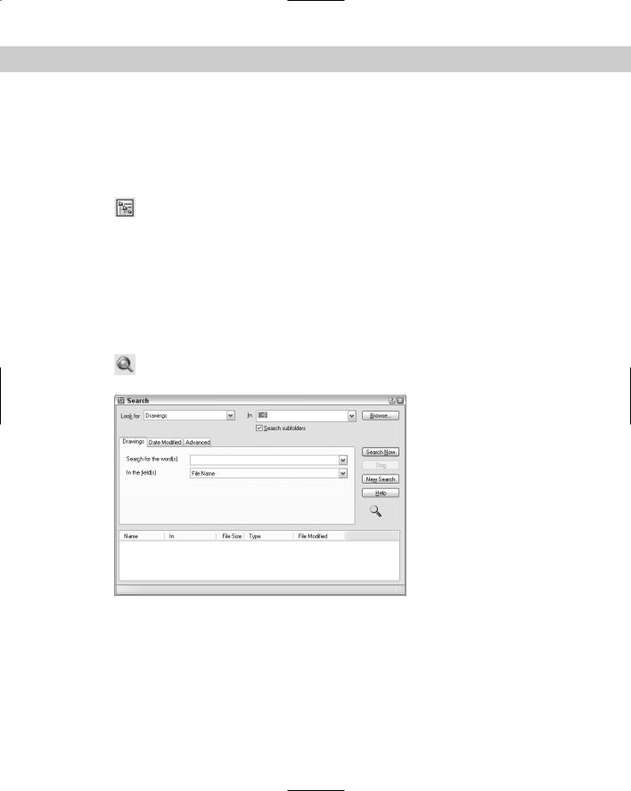
Choose Search from the DesignCenter toolbar to open the Search window, shown in Figure 26-2. (You can also right-click in the Content area and choose Search.)
Figure 26-2: Use the Search window to locate drawings and drawing components.
Here’s how to use the Search window:
Click the Look For drop-down list to choose what you’re looking for. You can look for blocks, dimension styles, drawings, drawings and blocks, hatch pattern files, hatch patterns, layers, layouts, linetypes, text styles, and xrefs.
Click the In drop-down list to specify the drive you want to look in. By default the Search subfolders check box is checked so that the search looks in all folders and subfolders within the drive.
782 Part V Organizing and Managing Drawings
Cross-
Reference
Use the tabbed area to specify the name of the components you’re looking for. The tab’s name and content changes depending on what you chose in the Look For drop-down list. For example, if you chose Layers, the tab is called Layers and asks you for the name of the layer. If you’re looking for drawings, you have three tabs to work with:
•The Drawings tab enables you to choose to look for a drawing by filename (the default), title, subject, author, or keywords. Choose one of these options in the In the Field(s) drop-down list. Then type the text you want to look for in the Search for the Word(s) text box. You can use the wildcards * (to substitute for any number of characters) and ? (to substitute for any one character). Specifying a drawing’s title, subject, and keywords is discussed later in this chapter.
•The Date Modified tab enables you to search by the last date the file was saved or modified. You can specify a range of dates or look in the last x days or months.
•The Advanced tab enables you to search for text in drawing descriptions, block names, attribute tags, and attribute values. You can also search here by drawing size.
When you’ve created your specifications, click Search Now.
See Chapter 18 for information on creating block descriptions when you create a block. The main reason for creating a block description is to display it in the DesignCenter and to be able to use it in a search on the Advanced tab, as just described.
Using the Favorites folder
The Favorites folder is a Windows convention that helps you to find files that you use often. This folder contains shortcuts to actual files. The files remain in their original locations. Choosing a file from the Favorites folder has the same effect as choosing the file from its source location.
You’ll find an Autodesk subfolder within the Favorites folder, where you can store shortcuts to drawings and other files that you use often. You can then easily open the Favorites folder and find these files. Favorites is one possible place to keep drawings that contain block libraries.
To add a shortcut to Favorites, right-click the drawing (or other file) in the DesignCenter and choose Add to Favorites.
Caution |
If you right-click in the content pane and choose Add to Favorites, the DesignCenter adds a |
|
shortcut to the entire content of the folder. This is great for adding all the items in a folder at |
|
once, but if you do it inadvertently, you could end up with lots of junk in Favorites. To add |
|
one item, remember to select it first. |
To access the drawings in Favorites, click Favorites on the DesignCenter toolbar. You can also right-click the content pane and choose Favorites. The Favorites folder
appears in the content pane.
To move, copy, or delete shortcuts from Favorites, right-click the Content pane and choose Organize Favorites.

Chapter 26 Keeping Control of Your Drawings |
783 |
Accessing named drawing components
As soon as you have the item you need in the content area, you need to insert it into your drawing. If you used the Search window to locate a file, you can also insert directly from results you get. You can either drag the item onto the drawing area or right-click it and choose an option. Sometimes these two methods provide slightly different results. In this section, I explain how to insert drawing components into your drawing.
Inserting drawings
You can insert an entire drawing into your drawing. Choose the drawing’s folder in the navigation pane so that the drawing appears in the content area. Drag the drawing’s icon onto the drawing area. The command line prompts you for an insertion point, scale, and rotation angle, using the -INSERT command.
If you right-click the drawing, you can choose to insert the drawing as a block or attach it as an xref.
Opening drawings
You can open a drawing using the DesignCenter. Display the drawing in the content pane, right-click it, and choose Open in Application Window. The drawing opens, keeping your current drawing open as well.
Inserting blocks
In Chapter 5, I explain that you can use the Units dialog box (choose Format Units) to set a unit, such as inches, for automatically scaling drawings when they’re inserted from the DesignCenter.
You can insert blocks in two ways:
If you drag the block’s icon onto the drawing area, the drawing uses Autoscaling, which compares the current drawing’s units with those of the block and scales the block appropriately, using the value set in the Units dialog box. The block takes on default scale and rotation.
If you double-click the block’s icon or right-click it and choose Insert Block, the Insert dialog box opens where you can specify the insertion point, scale, and rotation.
Inserting raster images
A raster image is a bitmap graphic file. You can insert raster images directly into your drawing — they don’t have to be within a drawing.
Cross- |
See Chapter 27 for more information on raster images, including determining which type of |
Reference |
files you can import, attaching images, clipping images, and controlling how they’re displayed. |
|
To attach a raster image, drag its icon onto the drawing area. The command line prompts you for an insertion point, scale, and rotation angle.
Tip |
Knowing the appropriate scale of an image before inserting it is often hard. When you move |
|
the cursor at the Specify scale factor or [Unit] <1>: prompt, you can see a |
|
bounding box that will help you visualize the resulting size of the image. |
784 Part V Organizing and Managing Drawings
Attaching an xref
To attach or overlay an xref, right-click its icon and choose Attach Xref to open the External Reference dialog box. Choose either Attachment or Overlay in the Reference Type section. Specify an insertion point, scale, and rotation (or choose to specify them on-screen) and click OK.
If you drag the xref onto the drawing area, you get prompts on the command line that are similar to those of the INSERT command.
Inserting layers and styles
To insert a layer, layout, linetype, text style, table style, or dimension style into a drawing, drag its icon onto the drawing area. Of course, these items don’t appear in your drawing area, but they’re added to the drawing’s database.
You can drag multiple items at one time. To select a contiguous group, click the first item, press and hold Shift, and click the last item. To select individual multiple items, click the first item, press and hold Ctrl, and click any other item you want to insert. You can also doubleclick an item to insert it.
Your drawing does not check for duplicate layer names. If you try to insert a layer with the same name as a layer in your current drawing, you see a message: Layer(s) added. Duplicate definitions will be ignored. You should check for duplicate layer names before trying to insert layers from the DesignCenter.
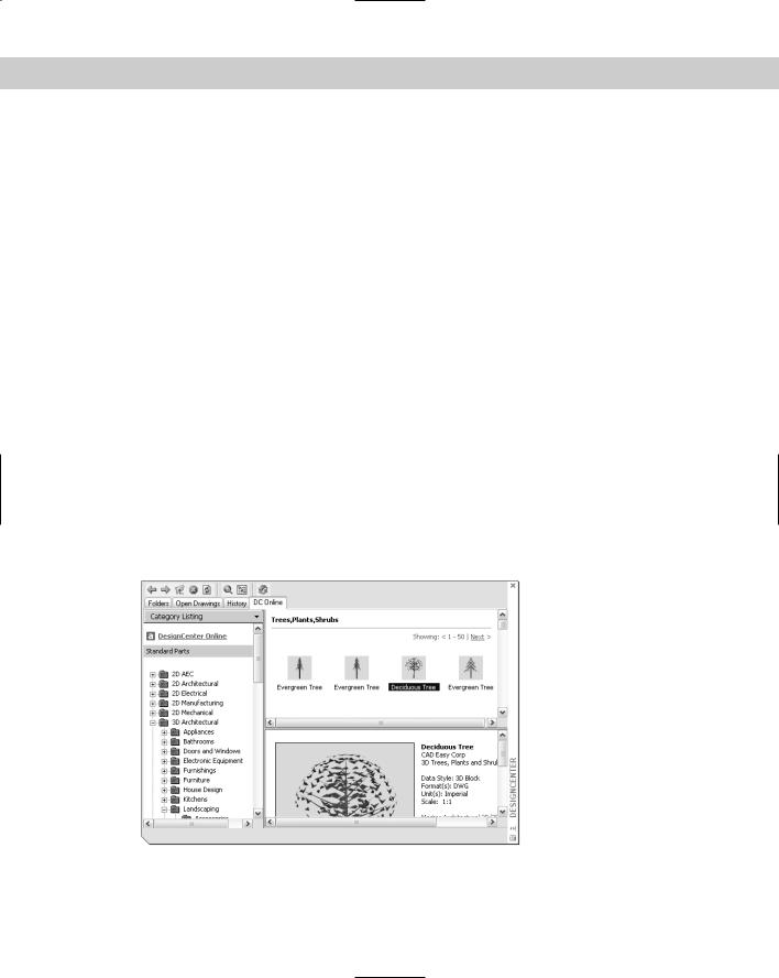
Inserting content from DC Online
The DC Online tab provides access to online resources, including standard parts and manufacturers’ information. Figure 26-3 shows some of the DC Online content. To insert any content, select it and drag it into your drawing. Follow the prompts for insertion point, scale, and rotation.
Figure 26-3: The DC Online tab of the DesignCenter offers a large selection of content that you can drag into your drawing.
Chapter 26 Keeping Control of Your Drawings |
785 |
Controlling the DesignCenter display
The DesignCenter provides several controls that help you manage its display.
A great feature of the DesignCenter is the preview pane. Click Preview and select the item in the content pane. You may or may not see a preview of a block. (The new Block
Definition dialog box specifically lets you create a preview icon.) Usually, you’ll see a preview of drawings and raster images. No previews exist for layers, linetypes, text styles, and so on.
If you saved a description with a block, select the block in the content pane and click Description on the DesignCenter toolbar to see the description.
To set the view, choose Views from the DesignCenter toolbar. The drop-down arrow lets you choose from four types of displays: large icons, small icons, list, and details.
If you make changes in the structure of a folder while the DesignCenter is open — for example, by deleting a drawing using Windows Explorer — right-click the navigation or content pane and choose Refresh. The DesignCenter re-reads the data and refreshes the list.
Tip |
To dock the DesignCenter, right-click the title bar and choose Allow Docking. Then drag the |
|
DesignCenter window to the left or right of your drawing window. To collapse the |
|
DesignCenter down to its title bar when you’re not using it, right-click the title bar and |
|
choose Auto-Hide; whenever you move the mouse cursor off the DesignCenter, it collapses. |
|
Just move the cursor back onto the title bar to expand it again. Sometimes the DesignCenter |
|
docks when you’re trying to drag it past the application window. To avoid unwanted docking, |
|
either uncheck Allow Docking on its title bar or press Ctrl as you drag. |
On the |
The drawings used in the following Step-by-Step exercise on using the DesignCenter, |
CD-ROM |
ab26-a.dwg and ab26-b.dwg, are in the Drawings folder on the CD-ROM. |
STEP-BY-STEP: Using the DesignCenter
1.Open ab26a-dwg from the CD-ROM.
2.Save the file as ab26-01.dwg in your AutoCAD Bible folder. This drawing needs an updated set of layers and a title block. It is shown in Figure 26-4.
3.Choose DesignCenter from the Standard toolbar. If the navigation pane is not displayed, click Tree View Toggle on the DesignCenter toolbar.
4.In the navigation pane, locate ab26-b.dwg on the CD-ROM. Click its plus sign.
5.Choose Blocks. The ansi_d block appears in the content pane. Double-click ansi_d. Uncheck any Specify Onscreen check boxes and click OK.
6.Do a Zoom Extents.
7.In the navigation pane, click Layers for ab26-b.dwg.
8.In the content pane, click the first layer, press and hold Shift, and click the last layer to select all the layers. Drag them onto the drawing area to import the layers.
9.Save your drawing.