

- •Foreword
- •Preface
- •Is This Book for You?
- •How This Book Is Organized
- •How to Use This Book
- •Doing the Exercises
- •Conventions Used in This Book
- •What the Icons Mean
- •About the CD-ROM
- •Other Information
- •Contacting the Author
- •Acknowledgments
- •Contents at a Glance
- •Contents
- •Getting Acquainted with AutoCAD and AutoCAD LT
- •Starting AutoCAD and AutoCAD LT
- •Creating a New Drawing
- •Using the AutoCAD and AutoCAD LT Interface
- •Creating Your First Drawing
- •Saving a Drawing
- •Summary
- •Creating a New Drawing from a Template
- •Working with Templates
- •Opening a Drawing with Default Settings
- •Opening an Existing Drawing
- •Using an Existing Drawing as a Prototype
- •Saving a Drawing Under a New Name
- •Summary
- •The Command Line
- •Command Techniques
- •Of Mice and Pucks
- •Getting Help
- •Summary
- •Typing Coordinates
- •Displaying Coordinates
- •Picking Coordinates on the Screen
- •Locating Points
- •Summary
- •Unit Types
- •Drawing Limits
- •Understanding Scales
- •Inserting a Title Block
- •Common Setup Options
- •The MVSETUP Command
- •Summary
- •Using the LINE Command
- •Drawing Rectangles
- •Drawing Polygons
- •Creating Construction Lines
- •Creating Rays
- •Summary
- •Drawing Circles
- •Drawing Arcs
- •Creating Ellipses and Elliptical Arcs
- •Making Donuts
- •Placing Points
- •Summary
- •Panning
- •The ZOOM Command
- •Aerial View
- •Named Views
- •Tiled Viewports
- •Snap Rotation
- •User Coordinate Systems
- •Isometric Drawing
- •Summary
- •Editing a Drawing
- •Selecting Objects
- •Summary
- •Copying and Moving Objects
- •Using Construction Commands
- •Creating a Revision Cloud
- •Hiding Objects with a Wipeout
- •Double-Clicking to Edit Objects
- •Grips
- •Editing with the Properties Palette
- •Selection Filters
- •Groups
- •Summary
- •Working with Layers
- •Changing Object Color, Linetype, and Lineweight
- •Working with Linetype Scales
- •Importing Layers and Linetypes from Other Drawings
- •Matching Properties
- •Summary
- •Drawing-Level Information
- •Object-Level Information
- •Measurement Commands
- •AutoCAD’s Calculator
- •Summary
- •Creating Single-Line Text
- •Understanding Text Styles
- •Creating Multiline Text
- •Creating Tables
- •Inserting Fields
- •Managing Text
- •Finding Text in Your Drawing
- •Checking Your Spelling
- •Summary
- •Working with Dimensions
- •Drawing Linear Dimensions
- •Drawing Aligned Dimensions
- •Creating Baseline and Continued Dimensions
- •Dimensioning Arcs and Circles
- •Dimensioning Angles
- •Creating Ordinate Dimensions
- •Drawing Leaders
- •Using Quick Dimension
- •Editing Dimensions
- •Summary
- •Understanding Dimension Styles
- •Defining a New Dimension Style
- •Changing Dimension Styles
- •Creating Geometric Tolerances
- •Summary
- •Creating and Editing Polylines
- •Drawing and Editing Splines
- •Creating Regions
- •Creating Boundaries
- •Creating Hatches
- •Creating and Editing Multilines
- •Creating Dlines
- •Using the SKETCH Command
- •Digitizing Drawings with the TABLET Command
- •Summary
- •Preparing a Drawing for Plotting or Printing
- •Creating a Layout in Paper Space
- •Working with Plot Styles
- •Plotting a Drawing
- •Summary
- •Combining Objects into Blocks
- •Inserting Blocks and Files into Drawings
- •Managing Blocks
- •Using Windows Features
- •Working with Attributes
- •Summary
- •Understanding External References
- •Editing an Xref within Your Drawing
- •Controlling Xref Display
- •Managing Xrefs
- •Summary
- •Preparing for Database Connectivity
- •Connecting to Your Database
- •Linking Data to Drawing Objects
- •Creating Labels
- •Querying with the Query Editor
- •Working with Query Files
- •Summary
- •Working with 3D Coordinates
- •Using Elevation and Thickness
- •Working with the User Coordinate System
- •Summary
- •Working with the Standard Viewpoints
- •Using DDVPOINT
- •Working with the Tripod and Compass
- •Getting a Quick Plan View
- •Shading Your Drawing
- •Using 3D Orbit
- •Using Tiled Viewports
- •Defining a Perspective View
- •Laying Out 3D Drawings
- •Summary
- •Drawing Surfaces with 3DFACE
- •Drawing Surfaces with PFACE
- •Creating Polygon Meshes with 3DMESH
- •Drawing Standard 3D Shapes
- •Drawing a Revolved Surface
- •Drawing an Extruded Surface
- •Drawing Ruled Surfaces
- •Drawing Edge Surfaces
- •Summary
- •Drawing Standard Shapes
- •Creating Extruded Solids
- •Drawing Revolved Solids
- •Creating Complex Solids
- •Sectioning and Slicing Solids
- •Using Editing Commands in 3D
- •Editing Solids
- •Listing Solid Properties
- •Summary
- •Understanding Rendering
- •Creating Lights
- •Creating Scenes
- •Working with Materials
- •Using Backgrounds
- •Doing the Final Render
- •Summary
- •Accessing Drawing Components with the DesignCenter
- •Accessing Drawing Content with Tool Palettes
- •Setting Standards for Drawings
- •Organizing Your Drawings
- •Working with Sheet Sets
- •Maintaining Security
- •Keeping Track of Referenced Files
- •Handling Errors and Crashes
- •Managing Drawings from Prior Releases
- •Summary
- •Importing and Exporting Other File Formats
- •Working with Raster Images
- •Pasting, Linking, and Embedding Objects
- •Summary
- •Sending Drawings
- •Opening Drawings from the Web
- •Creating Object Hyperlinks
- •Publishing Drawings
- •Summary
- •Working with Customizable Files
- •Creating Keyboard Shortcuts for Commands
- •Customizing Toolbars
- •Customizing Tool Palettes
- •Summary
- •Creating Macros with Script Files
- •Creating Slide Shows
- •Creating Slide Libraries
- •Summary
- •Creating Linetypes
- •Creating Hatch Patterns
- •Summary
- •Creating Shapes
- •Creating Fonts
- •Summary
- •Working with Menu Files
- •Customizing a Menu
- •Summary
- •Introducing Visual LISP
- •Getting Help in Visual LISP
- •Working with AutoLISP Expressions
- •Using AutoLISP on the Command Line
- •Creating AutoLISP Files
- •Summary
- •Creating Variables
- •Working with AutoCAD Commands
- •Working with Lists
- •Setting Conditions
- •Managing Drawing Objects
- •Getting Input from the User
- •Putting on the Finishing Touches
- •Summary
- •Understanding Local and Global Variables
- •Working with Visual LISP ActiveX Functions
- •Debugging Code
- •Summary
- •Starting to Work with VBA
- •Writing VBA Code
- •Getting User Input
- •Creating Dialog Boxes
- •Modifying Objects
- •Debugging and Trapping Errors
- •Moving to Advanced Programming
- •A Final Word
- •Installing AutoCAD and AutoCAD LT
- •Configuring AutoCAD
- •Starting AutoCAD Your Way
- •Configuring a Plotter
- •System Requirements
- •Using the CD with Microsoft Windows
- •What’s on the CD
- •Troubleshooting
- •Index
406 Part II Drawing in Two Dimensions
Creating Geometric Tolerances
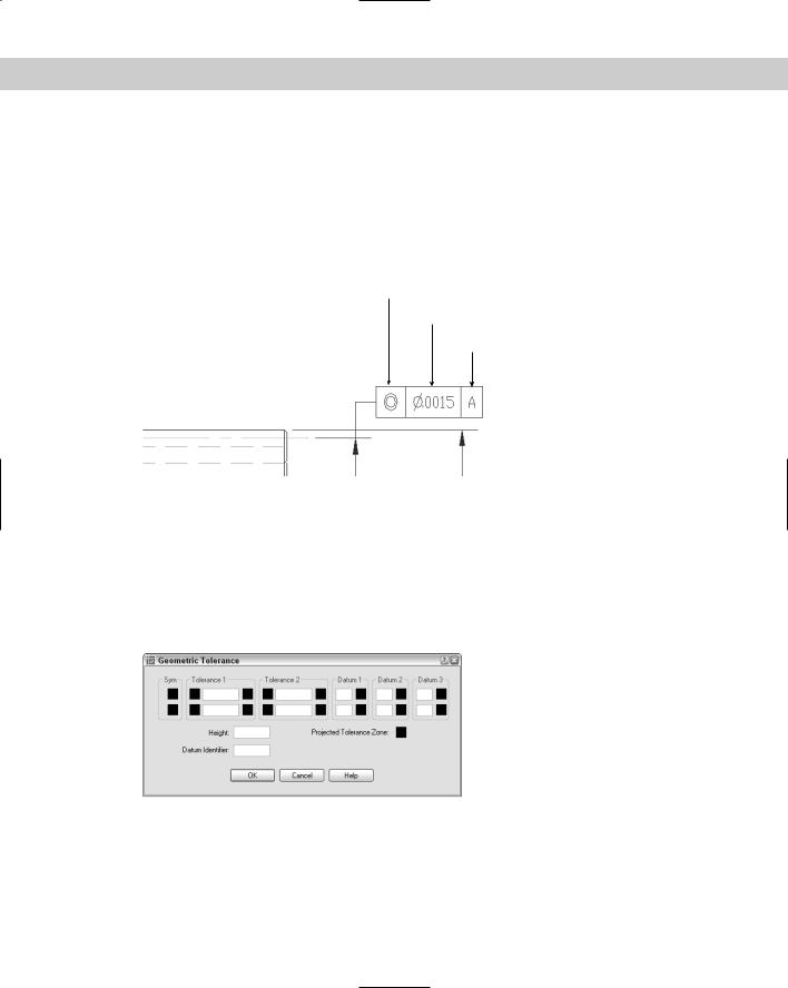
You can use the TOLERANCE command to create geometric tolerances. (For another way to specify tolerances, see the “Formatting tolerances” section earlier in this chapter.) This command creates feature control frames, which define tolerances. This method of denoting tolerances conforms to international standards such as ISO (International Standards Organization), ANSI (American National Standards Institute), or JIS (Japanese Industrial Standards). Figure 15-35 shows a drawing using tolerance feature control frames.
Tolerance symbol for concentricity
Tolerance value
Datum
Figure 15-35: An example of tolerance feature control frames.
Thanks to Jerry Butterfield of Clow Value Company, Oskaloosa, Iowa, for this drawing.
Starting the tolerance frame
Creating a tolerance frame is a step-by-step process that depends on what information you want to include. To start the frame, choose Tolerance from the Dimension toolbar, which opens the Geometric Tolerance dialog box, shown in Figure 15-36.
Figure 15-36: The Geometric Tolerance dialog box.
Chapter 15 Creating Dimension Styles and Tolerances |
407 |
Use this dialog box to build the frame. The frame enables you to create two rows of two tolerances, three datum references (for up to three dimensions), as well as a projected tolerance zone value and symbol and a datum identifier. You’ll rarely, if ever, use all the features in the frame.
Follow these steps to build the frame:
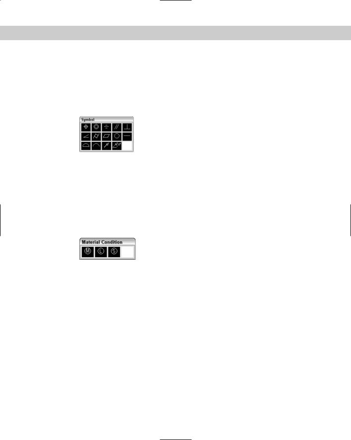
1. Click the first Sym box to open the Symbol dialog box, shown in Figure 15-37.
Figure 15-37: Use the Symbol dialog box to choose the symbol for the type of geometry for which you want to specify tolerance.
2.Choose the symbol for the geometric characteristic you are tolerancing. (Table 15-1 explains these symbols.) If you don’t need any symbol, click the blank box.
3.To insert a diameter symbol before the first tolerance, click the Dia box to the left of the text box in the Tolerance 1 section.
4.Type the tolerance value in the Value box.
5.If you want to specify a material condition, click the MC box to the right of the text box. The Material Condition dialog box opens, shown in Figure 15-38. Choose the symbol you want and click OK.
Figure 15-38: The Material Condition dialog box.
6.If desired, complete a second tolerance.
7.If desired, type a datum in the Datum box of the Datum 1 section, usually A.
8.If desired, add a material condition, using the same method described in Step 5.
9.If desired, type in datum references in the Datum 2 and Datum 3 sections, usually B and C with material conditions.
10.If you need to specify a projected tolerance zone for a perpendicular part, type in the height. Then click the Projected Tolerance Zone box to insert the Projected Tolerance Zone symbol.
11.Finally, if you want to specify a datum identifier, type the identifier letter in the Datum Identifier box.
12.Click OK to return to your drawing.
408 Part II Drawing in Two Dimensions
If you choose a material condition symbol and then change your mind, click the material condition box again and choose the blank square to delete your symbol.
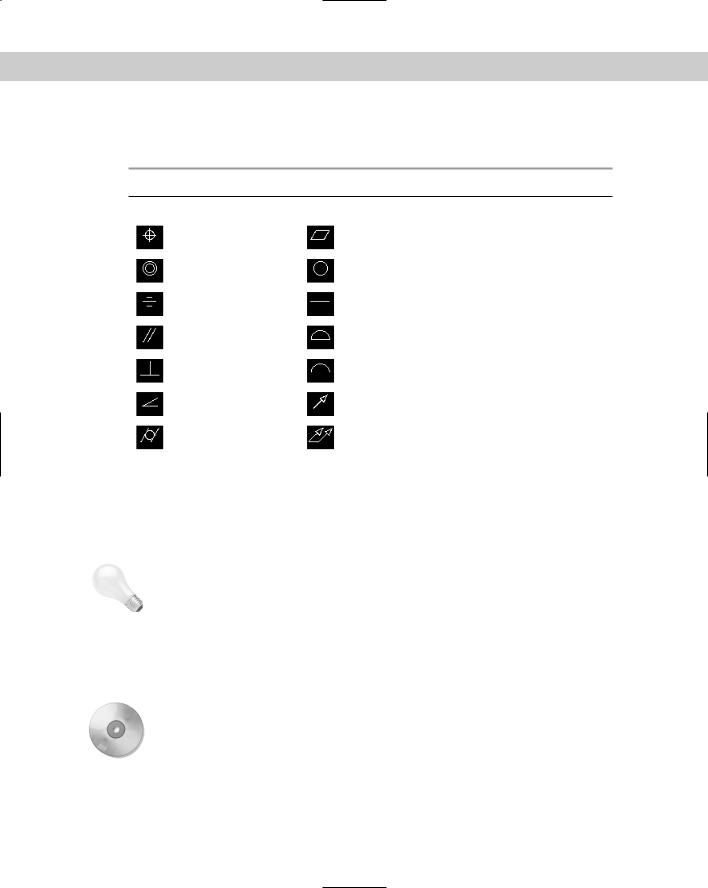
Table 15-1: Tolerance Symbols
Symbol |
Name |
Symbol |
Name |
|
|
|
|
|
Position |
|
Flatness |
|
Concentricity |
|
Circularity |
|
Symmetry |
|
Straightness |
|
Parallelism |
|
Surface profile |
|
Perpendicularity |
|
Line profile |
|
Angularity |
|
Circular runout |
|
Cylindricity |
|
Total runout |
|
|
|
|
|
Inserting the tolerance frame |
|
After you complete the frame, you’re returned to your drawing with the Enter tolerance |
|
location: prompt on the command line. Specify any point to insert the frame. |
Tip |
You can create a matching Datum reference to place on your model by creating a tolerance |
|
frame with no symbol and only the Datum letter. |
Editing a tolerance frame
To edit a geometric tolerance, double-click the tolerance frame. The Geometric Tolerance dialog box opens, and you can make any changes you need. Click OK to return to your drawing.
On the |
The drawing used in the following Step-by-Step exercise on creating geometric tolerances, |
CD-ROM |
ab15-c.dwg, is in the Drawings folder on the CD-ROM. |
Chapter 15 Creating Dimension Styles and Tolerances |
409 |
STEP-BY-STEP: Creating Geometric Tolerances
1.Open ab15-c.dwg from your CD-ROM.
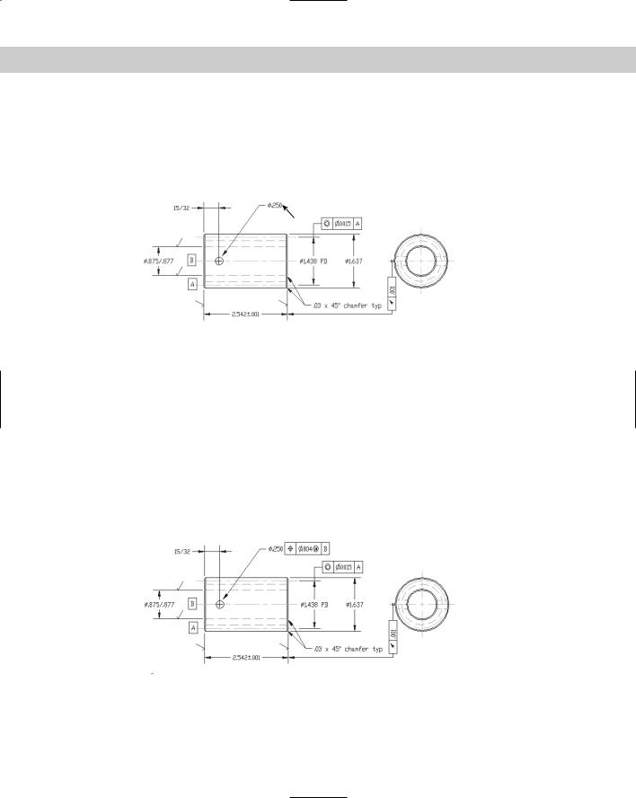
2.Save the file as ab15-06.dwg in your AutoCAD Bible folder. This drawing of a gear operator is shown in Figure 15-39. The Dim layer is current. If the Dimension toolbar is not visible, right-click any toolbar and choose Dimension.
1
Figure 15-39: A mechanical drawing using geometric tolerances.
3.Choose Tolerance from the Dimension toolbar. In the Geometric Tolerance dialog box, click the top-left box, labeled Sym.
4.The Symbol dialog box opens. Choose the top-left symbol (for position).
5.In the Tolerance 1 section of the Geometric Tolerance dialog box, click the next black box, the Dia box, to insert the diameter symbol. In the Value box, type .004. Click the next black box, the MC box. In the Material Condition dialog box, choose the first image tile (for Maximum material condition).
6.In the Datum 1 section, type B in the Datum box. Click OK.
7.At the Enter tolerance location: prompt, pick 1 in Figure 15-39 to place the geometric tolerance.
8.Save your drawing. It should look like Figure 15-40.
Figure 15-40: The drawing with the added geometric tolerance frame.