

- •Foreword
- •Preface
- •Is This Book for You?
- •How This Book Is Organized
- •How to Use This Book
- •Doing the Exercises
- •Conventions Used in This Book
- •What the Icons Mean
- •About the CD-ROM
- •Other Information
- •Contacting the Author
- •Acknowledgments
- •Contents at a Glance
- •Contents
- •Getting Acquainted with AutoCAD and AutoCAD LT
- •Starting AutoCAD and AutoCAD LT
- •Creating a New Drawing
- •Using the AutoCAD and AutoCAD LT Interface
- •Creating Your First Drawing
- •Saving a Drawing
- •Summary
- •Creating a New Drawing from a Template
- •Working with Templates
- •Opening a Drawing with Default Settings
- •Opening an Existing Drawing
- •Using an Existing Drawing as a Prototype
- •Saving a Drawing Under a New Name
- •Summary
- •The Command Line
- •Command Techniques
- •Of Mice and Pucks
- •Getting Help
- •Summary
- •Typing Coordinates
- •Displaying Coordinates
- •Picking Coordinates on the Screen
- •Locating Points
- •Summary
- •Unit Types
- •Drawing Limits
- •Understanding Scales
- •Inserting a Title Block
- •Common Setup Options
- •The MVSETUP Command
- •Summary
- •Using the LINE Command
- •Drawing Rectangles
- •Drawing Polygons
- •Creating Construction Lines
- •Creating Rays
- •Summary
- •Drawing Circles
- •Drawing Arcs
- •Creating Ellipses and Elliptical Arcs
- •Making Donuts
- •Placing Points
- •Summary
- •Panning
- •The ZOOM Command
- •Aerial View
- •Named Views
- •Tiled Viewports
- •Snap Rotation
- •User Coordinate Systems
- •Isometric Drawing
- •Summary
- •Editing a Drawing
- •Selecting Objects
- •Summary
- •Copying and Moving Objects
- •Using Construction Commands
- •Creating a Revision Cloud
- •Hiding Objects with a Wipeout
- •Double-Clicking to Edit Objects
- •Grips
- •Editing with the Properties Palette
- •Selection Filters
- •Groups
- •Summary
- •Working with Layers
- •Changing Object Color, Linetype, and Lineweight
- •Working with Linetype Scales
- •Importing Layers and Linetypes from Other Drawings
- •Matching Properties
- •Summary
- •Drawing-Level Information
- •Object-Level Information
- •Measurement Commands
- •AutoCAD’s Calculator
- •Summary
- •Creating Single-Line Text
- •Understanding Text Styles
- •Creating Multiline Text
- •Creating Tables
- •Inserting Fields
- •Managing Text
- •Finding Text in Your Drawing
- •Checking Your Spelling
- •Summary
- •Working with Dimensions
- •Drawing Linear Dimensions
- •Drawing Aligned Dimensions
- •Creating Baseline and Continued Dimensions
- •Dimensioning Arcs and Circles
- •Dimensioning Angles
- •Creating Ordinate Dimensions
- •Drawing Leaders
- •Using Quick Dimension
- •Editing Dimensions
- •Summary
- •Understanding Dimension Styles
- •Defining a New Dimension Style
- •Changing Dimension Styles
- •Creating Geometric Tolerances
- •Summary
- •Creating and Editing Polylines
- •Drawing and Editing Splines
- •Creating Regions
- •Creating Boundaries
- •Creating Hatches
- •Creating and Editing Multilines
- •Creating Dlines
- •Using the SKETCH Command
- •Digitizing Drawings with the TABLET Command
- •Summary
- •Preparing a Drawing for Plotting or Printing
- •Creating a Layout in Paper Space
- •Working with Plot Styles
- •Plotting a Drawing
- •Summary
- •Combining Objects into Blocks
- •Inserting Blocks and Files into Drawings
- •Managing Blocks
- •Using Windows Features
- •Working with Attributes
- •Summary
- •Understanding External References
- •Editing an Xref within Your Drawing
- •Controlling Xref Display
- •Managing Xrefs
- •Summary
- •Preparing for Database Connectivity
- •Connecting to Your Database
- •Linking Data to Drawing Objects
- •Creating Labels
- •Querying with the Query Editor
- •Working with Query Files
- •Summary
- •Working with 3D Coordinates
- •Using Elevation and Thickness
- •Working with the User Coordinate System
- •Summary
- •Working with the Standard Viewpoints
- •Using DDVPOINT
- •Working with the Tripod and Compass
- •Getting a Quick Plan View
- •Shading Your Drawing
- •Using 3D Orbit
- •Using Tiled Viewports
- •Defining a Perspective View
- •Laying Out 3D Drawings
- •Summary
- •Drawing Surfaces with 3DFACE
- •Drawing Surfaces with PFACE
- •Creating Polygon Meshes with 3DMESH
- •Drawing Standard 3D Shapes
- •Drawing a Revolved Surface
- •Drawing an Extruded Surface
- •Drawing Ruled Surfaces
- •Drawing Edge Surfaces
- •Summary
- •Drawing Standard Shapes
- •Creating Extruded Solids
- •Drawing Revolved Solids
- •Creating Complex Solids
- •Sectioning and Slicing Solids
- •Using Editing Commands in 3D
- •Editing Solids
- •Listing Solid Properties
- •Summary
- •Understanding Rendering
- •Creating Lights
- •Creating Scenes
- •Working with Materials
- •Using Backgrounds
- •Doing the Final Render
- •Summary
- •Accessing Drawing Components with the DesignCenter
- •Accessing Drawing Content with Tool Palettes
- •Setting Standards for Drawings
- •Organizing Your Drawings
- •Working with Sheet Sets
- •Maintaining Security
- •Keeping Track of Referenced Files
- •Handling Errors and Crashes
- •Managing Drawings from Prior Releases
- •Summary
- •Importing and Exporting Other File Formats
- •Working with Raster Images
- •Pasting, Linking, and Embedding Objects
- •Summary
- •Sending Drawings
- •Opening Drawings from the Web
- •Creating Object Hyperlinks
- •Publishing Drawings
- •Summary
- •Working with Customizable Files
- •Creating Keyboard Shortcuts for Commands
- •Customizing Toolbars
- •Customizing Tool Palettes
- •Summary
- •Creating Macros with Script Files
- •Creating Slide Shows
- •Creating Slide Libraries
- •Summary
- •Creating Linetypes
- •Creating Hatch Patterns
- •Summary
- •Creating Shapes
- •Creating Fonts
- •Summary
- •Working with Menu Files
- •Customizing a Menu
- •Summary
- •Introducing Visual LISP
- •Getting Help in Visual LISP
- •Working with AutoLISP Expressions
- •Using AutoLISP on the Command Line
- •Creating AutoLISP Files
- •Summary
- •Creating Variables
- •Working with AutoCAD Commands
- •Working with Lists
- •Setting Conditions
- •Managing Drawing Objects
- •Getting Input from the User
- •Putting on the Finishing Touches
- •Summary
- •Understanding Local and Global Variables
- •Working with Visual LISP ActiveX Functions
- •Debugging Code
- •Summary
- •Starting to Work with VBA
- •Writing VBA Code
- •Getting User Input
- •Creating Dialog Boxes
- •Modifying Objects
- •Debugging and Trapping Errors
- •Moving to Advanced Programming
- •A Final Word
- •Installing AutoCAD and AutoCAD LT
- •Configuring AutoCAD
- •Starting AutoCAD Your Way
- •Configuring a Plotter
- •System Requirements
- •Using the CD with Microsoft Windows
- •What’s on the CD
- •Troubleshooting
- •Index
Chapter 22 Viewing 3D Drawings 629
Figure 22-16: This cursor location results in the viewpoint shown in Figure 22-17.
Figure 22-17: This viewpoint results from the cursor location on the compass shown in Figure 22-16.
Getting a Quick Plan View
The PLAN command is a quick way to return to plan view. Type plan . This command has three options:
<Current UCS>: This is the default. You get the plan view of the current UCS.
UCS: The UCS option enables you to choose a named UCS. Type ? to get a list of the named UCSs. Otherwise, type the name of a UCS.
World: This option gives you the plan view of the WCS. If your current UCS is the WCS, there is no difference between this option and the Current UCS option.
Figure 22-18 shows a sample UCS listing. Note that the units are architectural.
630 Part IV Drawing in Three Dimensions
Returning to plan view when you change the UCS
If you like plan views, you’ll love UCSFOLLOW. UCSFOLLOW is a system variable that returns you to plan view whenever you change the UCS. It’s for those who like to get their bearings in plan view first before going on to change the viewpoint in another UCS.
Most 2D objects you use in 3D drawings can only be drawn and edited in plan view because they don’t interpret the Z coordinate. Therefore, returning to plan view is helpful in many situations.
The default value is 0 (off), which means that your drawing does not return to plan view. In other words, your display remains unchanged when you change the UCS. Type ucsfollow and change the value to 1 to turn UCSFOLLOW on. From then on, your drawing automatically displays the plan view when you change the UCS.
Figure 22-18: A listing of saved UCSs.
The Express Tools’ extended PLAN command, EXPLAN, prompts you to select objects so that you can see the plan view zoomed in on those objects. Choose Express Tools Extended Plan. For information about installing Express Tools, see Appendix A.
Shading Your Drawing
Shading is a simple version of rendering. You can use shading to get a quick visualization of your drawing. Shading is based on one default light source that is behind the viewer and shines on the model.
Shading is different in AutoCAD and AutoCAD LT, as follows:
In AutoCAD, you can edit your objects in Shaded mode. When you select shaded objects, the wireframe display and grips appear over the shading to help you work. Objects remain shaded until you choose to unshade them, even if you regenerate or close and reopen the drawing. You can display different shading in different viewports. Because shading can now stay on as you edit, it has been transformed from a simple form of rendering into a means of viewing your drawing while you work.
In AutoCAD LT, you cannot edit your objects in Shaded mode, which is a better-looking version of the HIDE command. If you regenerate the drawing, the shading goes away.
Objects in color shade better than objects in black and white.

Chapter 22 Viewing 3D Drawings 631
Using the shading options in AutoCAD
To shade in AutoCAD, choose View Shade or type shademode . Here are the options:
2D Wireframe: Displays objects in the familiar wireframe display, with no shading. Choose this option to return to “normal.”
3D Wireframe: Displays objects in wireframe along with a shaded UCS icon. Raster (bitmap) and OLE (embedded) objects, linetypes, and lineweights are not visible.
Hidden: Equivalent to using the HIDE command.
Flat Shaded: Creates flat blocks of color between each polygon face. There is no smoothing from face to face.
Gouraud Shaded: Creates smoothed shading from face to face, resulting in a more realistic appearance, especially for curved surfaces.
Flat Shaded, Edges On: Combines flat shading and wireframe display. Useful for editing objects while they’re shaded.
Gouraud Shaded, Edges On: Combines Gouraud shading and wireframe display. Useful for editing objects while they’re shaded.
Note The FACETRATIO system variable affects the mesh density created for cylindrical and conic solids. By default, it is set to 0 (zero), which creates the normal mesh density. Set it to 1 to increase the mesh density. This should improve the quality of rendered and shaded cylindrical and conic solids.
Using the shading options in AutoCAD LT
The SHADEMODE command in AutoCAD LT has only two options — 2D Wireframe and Hidden. The 2D Wireframe option allows you to turn off the shading in a viewport set for one of the options only available in AutoCAD. However, AutoCAD LT has a SHADE command that provides the following options:
256 Color: Displays shaded faces. Shading is flat, but curved faces give the impression of gradual shading because they’re broken up into many faces, each a slightly different color.
256 Color Edge Highlight: Like 256 Color, but highlights edges using the same color as your drawing background.
16 Color Hidden Line: Looks like a hidden display. The non-hidden edges are in the object’s color and the faces are the color of the background of the drawing area.
16 Color Filled: The reverse of 16 Color Hidden Line, so that the faces are in the object’s color and non-hidden edges are the background color.
Using materials
Materials are used in rendering, which is covered in Chapter 25. You can set your 3D graphics system display properties to display materials that you’ve attached to objects. Then, shaded objects display these materials. You can also display lights and textures. The difference in the quality of your image is striking. You can see the effect in 3D orbit as well when you use one of the shading options.
632 Part IV Drawing in Three Dimensions
New |
You can now display backgrounds that you create with the BACKGROUND command. See |
Feature |
Chapter 25 for more information on backgrounds. |
|
Lights in 3D orbit and SHADEMODE do not display shadows, have no attenuation, and use a default light intensity instead of the light intensity specified with the LIGHT command. Materials in 3D orbit and SHADEMODE display the color/pattern material component only. 3D textures are not shown; neither are bump maps, opacity maps, refraction, and reflection. For more information, see Chapter 25.
Here’s how to set your display to show materials, textures, lights, and a background:
1.Choose Tools Options and choose the System tab.
2.In Current 3D Graphics Display, choose your graphics system (it’s probably already selected) and click Properties.
3.In the 3D Graphics System Configuration dialog box, check Render Options.
4.Check the types of effects you want to display. You can choose to display a background, lights, materials, and textures.
5.Choose one of the transparency options: high, medium, or low quality.
6.Click Apply & Close.
7.Click OK to close the Options dialog box.
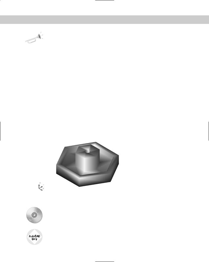
For information about how to attach a material to an object, see Chapter 25. Figure 22-19 shows a model with the Brassy Valley material attached, viewed with Gouraud shading.
Figure 22-19: A model with Gouraud shading and the
Brassy Valley material attached. (It looks better in color!).
On the |
The drawing used in the following Step-by-Step exercise on shading a drawing, ab22-b. |
CD-ROM |
dwg, is in the Drawings folder on the CD-ROM. |
This exercise is for AutoCAD only. AutoCAD LT doesn’t offer these shading options.