

- •Foreword
- •Preface
- •Is This Book for You?
- •How This Book Is Organized
- •How to Use This Book
- •Doing the Exercises
- •Conventions Used in This Book
- •What the Icons Mean
- •About the CD-ROM
- •Other Information
- •Contacting the Author
- •Acknowledgments
- •Contents at a Glance
- •Contents
- •Getting Acquainted with AutoCAD and AutoCAD LT
- •Starting AutoCAD and AutoCAD LT
- •Creating a New Drawing
- •Using the AutoCAD and AutoCAD LT Interface
- •Creating Your First Drawing
- •Saving a Drawing
- •Summary
- •Creating a New Drawing from a Template
- •Working with Templates
- •Opening a Drawing with Default Settings
- •Opening an Existing Drawing
- •Using an Existing Drawing as a Prototype
- •Saving a Drawing Under a New Name
- •Summary
- •The Command Line
- •Command Techniques
- •Of Mice and Pucks
- •Getting Help
- •Summary
- •Typing Coordinates
- •Displaying Coordinates
- •Picking Coordinates on the Screen
- •Locating Points
- •Summary
- •Unit Types
- •Drawing Limits
- •Understanding Scales
- •Inserting a Title Block
- •Common Setup Options
- •The MVSETUP Command
- •Summary
- •Using the LINE Command
- •Drawing Rectangles
- •Drawing Polygons
- •Creating Construction Lines
- •Creating Rays
- •Summary
- •Drawing Circles
- •Drawing Arcs
- •Creating Ellipses and Elliptical Arcs
- •Making Donuts
- •Placing Points
- •Summary
- •Panning
- •The ZOOM Command
- •Aerial View
- •Named Views
- •Tiled Viewports
- •Snap Rotation
- •User Coordinate Systems
- •Isometric Drawing
- •Summary
- •Editing a Drawing
- •Selecting Objects
- •Summary
- •Copying and Moving Objects
- •Using Construction Commands
- •Creating a Revision Cloud
- •Hiding Objects with a Wipeout
- •Double-Clicking to Edit Objects
- •Grips
- •Editing with the Properties Palette
- •Selection Filters
- •Groups
- •Summary
- •Working with Layers
- •Changing Object Color, Linetype, and Lineweight
- •Working with Linetype Scales
- •Importing Layers and Linetypes from Other Drawings
- •Matching Properties
- •Summary
- •Drawing-Level Information
- •Object-Level Information
- •Measurement Commands
- •AutoCAD’s Calculator
- •Summary
- •Creating Single-Line Text
- •Understanding Text Styles
- •Creating Multiline Text
- •Creating Tables
- •Inserting Fields
- •Managing Text
- •Finding Text in Your Drawing
- •Checking Your Spelling
- •Summary
- •Working with Dimensions
- •Drawing Linear Dimensions
- •Drawing Aligned Dimensions
- •Creating Baseline and Continued Dimensions
- •Dimensioning Arcs and Circles
- •Dimensioning Angles
- •Creating Ordinate Dimensions
- •Drawing Leaders
- •Using Quick Dimension
- •Editing Dimensions
- •Summary
- •Understanding Dimension Styles
- •Defining a New Dimension Style
- •Changing Dimension Styles
- •Creating Geometric Tolerances
- •Summary
- •Creating and Editing Polylines
- •Drawing and Editing Splines
- •Creating Regions
- •Creating Boundaries
- •Creating Hatches
- •Creating and Editing Multilines
- •Creating Dlines
- •Using the SKETCH Command
- •Digitizing Drawings with the TABLET Command
- •Summary
- •Preparing a Drawing for Plotting or Printing
- •Creating a Layout in Paper Space
- •Working with Plot Styles
- •Plotting a Drawing
- •Summary
- •Combining Objects into Blocks
- •Inserting Blocks and Files into Drawings
- •Managing Blocks
- •Using Windows Features
- •Working with Attributes
- •Summary
- •Understanding External References
- •Editing an Xref within Your Drawing
- •Controlling Xref Display
- •Managing Xrefs
- •Summary
- •Preparing for Database Connectivity
- •Connecting to Your Database
- •Linking Data to Drawing Objects
- •Creating Labels
- •Querying with the Query Editor
- •Working with Query Files
- •Summary
- •Working with 3D Coordinates
- •Using Elevation and Thickness
- •Working with the User Coordinate System
- •Summary
- •Working with the Standard Viewpoints
- •Using DDVPOINT
- •Working with the Tripod and Compass
- •Getting a Quick Plan View
- •Shading Your Drawing
- •Using 3D Orbit
- •Using Tiled Viewports
- •Defining a Perspective View
- •Laying Out 3D Drawings
- •Summary
- •Drawing Surfaces with 3DFACE
- •Drawing Surfaces with PFACE
- •Creating Polygon Meshes with 3DMESH
- •Drawing Standard 3D Shapes
- •Drawing a Revolved Surface
- •Drawing an Extruded Surface
- •Drawing Ruled Surfaces
- •Drawing Edge Surfaces
- •Summary
- •Drawing Standard Shapes
- •Creating Extruded Solids
- •Drawing Revolved Solids
- •Creating Complex Solids
- •Sectioning and Slicing Solids
- •Using Editing Commands in 3D
- •Editing Solids
- •Listing Solid Properties
- •Summary
- •Understanding Rendering
- •Creating Lights
- •Creating Scenes
- •Working with Materials
- •Using Backgrounds
- •Doing the Final Render
- •Summary
- •Accessing Drawing Components with the DesignCenter
- •Accessing Drawing Content with Tool Palettes
- •Setting Standards for Drawings
- •Organizing Your Drawings
- •Working with Sheet Sets
- •Maintaining Security
- •Keeping Track of Referenced Files
- •Handling Errors and Crashes
- •Managing Drawings from Prior Releases
- •Summary
- •Importing and Exporting Other File Formats
- •Working with Raster Images
- •Pasting, Linking, and Embedding Objects
- •Summary
- •Sending Drawings
- •Opening Drawings from the Web
- •Creating Object Hyperlinks
- •Publishing Drawings
- •Summary
- •Working with Customizable Files
- •Creating Keyboard Shortcuts for Commands
- •Customizing Toolbars
- •Customizing Tool Palettes
- •Summary
- •Creating Macros with Script Files
- •Creating Slide Shows
- •Creating Slide Libraries
- •Summary
- •Creating Linetypes
- •Creating Hatch Patterns
- •Summary
- •Creating Shapes
- •Creating Fonts
- •Summary
- •Working with Menu Files
- •Customizing a Menu
- •Summary
- •Introducing Visual LISP
- •Getting Help in Visual LISP
- •Working with AutoLISP Expressions
- •Using AutoLISP on the Command Line
- •Creating AutoLISP Files
- •Summary
- •Creating Variables
- •Working with AutoCAD Commands
- •Working with Lists
- •Setting Conditions
- •Managing Drawing Objects
- •Getting Input from the User
- •Putting on the Finishing Touches
- •Summary
- •Understanding Local and Global Variables
- •Working with Visual LISP ActiveX Functions
- •Debugging Code
- •Summary
- •Starting to Work with VBA
- •Writing VBA Code
- •Getting User Input
- •Creating Dialog Boxes
- •Modifying Objects
- •Debugging and Trapping Errors
- •Moving to Advanced Programming
- •A Final Word
- •Installing AutoCAD and AutoCAD LT
- •Configuring AutoCAD
- •Starting AutoCAD Your Way
- •Configuring a Plotter
- •System Requirements
- •Using the CD with Microsoft Windows
- •What’s on the CD
- •Troubleshooting
- •Index

494 Part III Working with Data
Inserting Blocks and Files into Drawings
Blocks that are defined in a drawing are inserted in the same way as separate drawing files. After you choose the location, you can change the size and rotation of the block. This capability is ideal for parts libraries. Parts may be created at the size of 1 unit and then scaled or rotated as needed. Figure 18-7 shows a window block inserted at various scales and rotation angles.
Figure 18-7: A block of a window inserted at various rotation angles and scales.
Using the Insert dialog box
To insert a block or file, follow these steps:
1.Choose Insert Block from the Draw toolbar to start the INSERT command. The Insert dialog box (shown in Figure 18-8) opens.
Figure 18-8: The Insert dialog box.

Chapter 18 Working with Blocks and Attributes |
495 |
2.You can insert a block or a file as follows:
•To insert a block from within your drawing, click the Name drop-down list and choose one of the existing blocks.
•To insert a file, click Browse. The Select Drawing File dialog box opens. Locate the file’s drive and folder and then choose the file. A preview appears to the right. Click Open. The Insert dialog box displays the path of the file.
3.Uncheck Specify On-Screen in the Insertion point, Scale, and Rotation sections if you want to specify the insertion point, scale, and rotation angle in the dialog box. Then provide the requested information in the dialog box.
4.Check the Explode check box if you want to insert the block as individual objects instead of as one block object.
5.Click OK to close the Insert dialog box.
6.If any of the Specify On-Screen checkboxes were checked, the command line prompts you for the necessary information:
•At the Specify insertion point: prompt (which varies depending on whether or not you checked the Explode check box in Step 4), specify the insertion point. You see the block with its base point at the cursor so you can judge how it looks.
•At the Enter X scale factor, specify opposite corner, or [Corner/XYZ] <1>: prompt, press Enter to accept the default scale factor of 1, or type another scale. The Specify Opposite Corner option lets you define a square box whose side defines the scale factor. A side of 1 unit results in a scale factor of 1. If you specify the X scale factor, the command line now prompts you for the Y scale factor. The default is the same scale as X, but you can specify a different one. For 3D models, use the XYZ option to specify all three scale factors. (If you checked Explode,
the prompt is slightly different and you specify the scale factor for all directions at once.)
•At the Specify rotation angle <0>: prompt, type in a rotation angle. You can also pick a point to use the angle from the insertion point to the point you picked as the rotation angle. This technique is useful for aligning a block with an existing object.
After you provide all the necessary information, the command inserts the block or file.
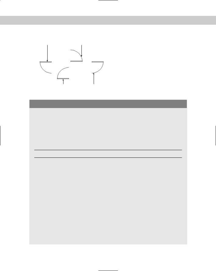
A negative scale factor for any of the axes creates a mirror image of the block or file. When you specify a negative X scale axis, the block is mirrored around the Y axis. When you specify a negative Y scale axis, the block is mirrored around the X axis. Figure 18-9 shows a door block inserted with positive and negative scale factors. The rotation angle of all the blocks
is 0 degrees. By combining negative and positive scale factors with rotation angles, you can get any door configuration you want. Sometimes it can be difficult to visualize the result of a negative scale combined with a rotation angle. See the sidebar, “Presetting scale and rotation while inserting a block,” for a solution.
When you insert a drawing file, paper space objects are not included in the block definition created in your drawing. To insert paper space objects in another drawing, open the original drawing and define the objects as a block. Then use the DesignCenter to insert that block into any other drawing.
496 Part III Working with Data
X scale factor = -1 Y scale factor = -1
X scale factor = -1 Y scale factor = 1
X scale factor = 1 Y scale factor = 1
X scale factor = 1 Y scale factor = -1
Figure 18-9: A door block inserted at various positive and negative scale factors, creating mirror images in different directions.
Presetting scale and rotation while inserting a block
When you’re dragging a block on the screen to specify an insertion point, it may be helpful to see the block at the scale and rotation angle you want. The problem is that the prompts for scale and rotation come after the prompt for the insertion point. If you use the command-line version of INSERT, by typing -insert, you can preset the scale and rotation angle at the first prompt, using the options shown here. To use one of these options, right-click and choose the option from the shortcut menu at the Specify insertion point or [Scale/X/Y/Z/Rotate/PScale/PX/PY/ PZ/PRotate]: prompt. All the prompts appear on the command line, including the prompt for the name of the block or file you want to insert.
Option Use
Scale |
Specifies the scale factor |
XSpecifies the X scale factor
YSpecifies the Y scale factor
ZSpecifies the Z scale factor
Rotate |
Specifies the rotation angle |
PScale |
Specifies the preliminary scale factor for the display of the block as you drag it and prompts |
|
you again for the scale so you can change it |
Pxscale |
Specifies the preliminary X scale factor for the display of the block as you drag it and |
|
prompts you again for the scale so you can change it |
Pyscale |
Specifies the preliminary Y scale factor for the display of the block as you drag it and |
|
prompts you again for the scale so you can change it |
PZscale |
Specifies the preliminary Z scale factor for the display of the block as you drag it and |
|
prompts you again for the scale so you can change it |
PRotate |
Specifies the preliminary rotation angle for the display of the block as you drag it and |
|
prompts you again for the rotation angle so you can change it |
|
|
Chapter 18 Working with Blocks and Attributes |
497 |
Using the DesignCenter
When you want to insert a block from within another drawing, use the DesignCenter. Choose DesignCenter from the Standard toolbar. In the left pane, navigate to the drawing that contains the block you want. Double-click the drawing and choose Blocks from the list that appears. In the right pane, you see a list of the blocks in that drawing. Click Preview to see a preview of each block you select. Click Description to see a description of the block. (The description only appears if you saved one when creating the block.) There are two ways to insert the block:
Double-click the block’s icon to open the Insert dialog box so you can specify exactly how you want to insert the block, just as I described earlier for blocks within a drawing.
Drag the block’s icon onto the drawing area to insert the block at the point where you release the mouse button, using the default scale and rotation.
You can also use the DesignCenter to insert entire drawings. In the left pane, navigate to the folder containing the drawing. The drawings are then listed in the right pane. Choose a drawing and drag it onto the drawing area. On the command line, you’ll see the -INSERT command, the command line version of INSERT. You can simply specify an insertion point, scale, and rotation, or you can use the options described in the sidebar, “Presetting scale and rotation while inserting a block.”
Cross-
Reference
On the
CD-ROM
You can also insert blocks from a tool palette. See Chapter 26 for details.
The drawings you need for the following Step-by-Step exercise on inserting blocks, ab14- b.dwg and ab18-c.dwg, are in the Drawings folder on the CD-ROM.
STEP-BY-STEP: Inserting Blocks
1.Open ab18-c.dwg from the CD-ROM.
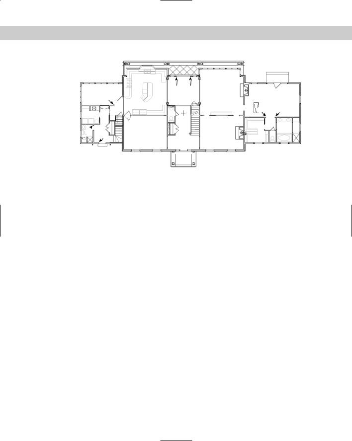
2.Save the file as ab18-03.dwg in your AutoCAD Bible folder. This is the floor plan of the first floor of a house, as shown in Figure 18-10. Many of the doors and a toilet need to be inserted. OSNAP should be on. Set running object snaps for endpoint and midpoint. The current layer is Door.
3.Use Zoom Window to zoom in on the left third of the house.
4.Choose Insert Block from the Draw toolbar. In the Name drop-down list of the
Insert dialog box, choose DOOR (if it isn’t already selected). Check all three Specify On-Screen check boxes. Click OK to close the Insert dialog box.
Tip |
If you make a mistake while inserting a door, press Esc if you’re in the middle of the prompts. |
|
If you’ve completed the command, click Undo on the Standard toolbar or erase the door and |
|
start over. |
498 Part III Working with Data
4 5
3
6 7
2
1
Figure 18-10: The floor plan of the house needs some doors and a new toilet.
5.As you move the cursor, you can see the dragged image of a door. This image shows you the block at an X and Y scale of 1 and a 0-degree rotation angle. Follow the prompts:
Specify insertion point or [Scale/X/Y/Z/Rotate/PScale/PX/PY/PZ/ PRotate]: Use the Endpoint object snap to pick 1 in Figure 18-10.
Enter X scale factor, specify opposite corner, or [Corner/XYZ] <1>:
–1
Enter Y scale factor <use X scale factor>: 1
Specify rotation angle <0>: 270 (You could also specify –90 degrees.)
6.Repeat the INSERT command. The Insert dialog box already shows the DOOR block. Click OK. Follow the prompts. You’ll probably want to use Zoom Window to zoom into the area of 2 in Figure 18-10.
Specify insertion point or [Scale/X/Y/Z/Rotate/PScale/PX/PY/PZ/ PRotate]: Pick 2 in Figure 18-10.
Enter X scale factor, specify opposite corner, or [Corner/XYZ] <1>:
2/3
Enter Y scale factor <use X scale factor>: Specify rotation angle <0>: 180
7.If you zoomed in for the previous step, return to the previous view using Zoom Previous. Zoom in to the area around 3 in Figure 18-10. Choose Insert Block from the Draw toolbar. Click OK. Follow the prompts:
Specify insertion point or [Scale/X/Y/Z/Rotate/PScale/PX/PY/PZ/ PRotate]: Pick 3 in Figure 18-10.
Enter X scale factor or specify opposite corner, or [Corner/XYZ] <1>:
–3/4
Enter Y scale factor <use X scale factor>: 3/4 Specify rotation angle <0>: 315

Chapter 18 Working with Blocks and Attributes |
499 |
8.Use Zoom Dynamic to zoom in to the area around 4 and 5 in Figure 18-10. Choose Insert Block from the Draw toolbar. Click OK. Follow the prompts:
Specify insertion point or [Scale/X/Y/Z/Rotate/PScale/PX/PY/PZ/ PRotate]: Pick 4 in Figure 18-10.
Enter X scale factor, specify opposite corner, or [Corner/XYZ] <1>:
1
Enter Y scale factor <use X scale factor>: Specify rotation angle <0>: 270
9.Repeat the INSERT command and click OK. Follow the prompts:
Specify insertion point or [Scale/X/Y/Z/Rotate/PScale/PX/PY/PZ/ PRotate]: Pick 5 in Figure 18-11.
Enter X scale factor, specify opposite corner, or [Corner/XYZ] <1>: –1 Enter Y scale factor <use X scale factor>: 1
Specify rotation angle <0>: 90
10.Use Zoom Dynamic to zoom in on the area around 6 and 7 in Figure 18-10. Start the INSERT command and click OK. Follow the prompts:
Specify insertion point or [Scale/X/Y/Z/Rotate/PScale/PX/PY/PZ/ PRotate]: Pick 6 in Figure 18-10.
Enter X scale factor, specify opposite corner, or [Corner/XYZ] <1>:
–2/3
Enter Y scale factor <use X scale factor>: 2/3 Specify rotation angle: 270
11.Repeat the INSERT command and click OK. Follow the prompts:
Specify insertion point or [Scale/X/Y/Z/Rotate/PScale/PX/PY/PZ/ PRotate]: Pick 7 in Figure 18-10.
Enter X scale factor, specify opposite corner, or [Corner/XYZ] <1>:
2/3
Enter Y scale factor <use X scale factor>: Specify rotation angle: 90
12.Beneath the doors you just inserted is a water closet with a toilet. Pan down to it. Erase the toilet, which is a block. Change the current layer to FIXTURE.
13.Choose DesignCenter from the Standard toolbar. (If you don’t see the two panes, click Tree View Toggle on the DesignCenter toolbar.) In the left pane, navigate to your CD-ROM drive. (You may need to use the horizontal scroll bar if the left side of the list of drives and folders is not in view.) Double-click the CD-ROM drive and then double-click ab14-b. dwg. Click Blocks from the list of named objects. On the right, you see the blocks in the drawing.
14.Double-click TOILET2. You see a preview at the bottom of the DesignCenter. (If you don’t, click Preview on the DesignCenter toolbar.) The Insert dialog box opens. Because you can see the preview, you know the rotation angle is correct; you can assume that the scale is correct because toilets are generally about the same size. The Insertion Point Specify On-Screen check box should be checked. The other Specify On-Screen check boxes should be unchecked. Click OK.