

- •Foreword
- •Preface
- •Is This Book for You?
- •How This Book Is Organized
- •How to Use This Book
- •Doing the Exercises
- •Conventions Used in This Book
- •What the Icons Mean
- •About the CD-ROM
- •Other Information
- •Contacting the Author
- •Acknowledgments
- •Contents at a Glance
- •Contents
- •Getting Acquainted with AutoCAD and AutoCAD LT
- •Starting AutoCAD and AutoCAD LT
- •Creating a New Drawing
- •Using the AutoCAD and AutoCAD LT Interface
- •Creating Your First Drawing
- •Saving a Drawing
- •Summary
- •Creating a New Drawing from a Template
- •Working with Templates
- •Opening a Drawing with Default Settings
- •Opening an Existing Drawing
- •Using an Existing Drawing as a Prototype
- •Saving a Drawing Under a New Name
- •Summary
- •The Command Line
- •Command Techniques
- •Of Mice and Pucks
- •Getting Help
- •Summary
- •Typing Coordinates
- •Displaying Coordinates
- •Picking Coordinates on the Screen
- •Locating Points
- •Summary
- •Unit Types
- •Drawing Limits
- •Understanding Scales
- •Inserting a Title Block
- •Common Setup Options
- •The MVSETUP Command
- •Summary
- •Using the LINE Command
- •Drawing Rectangles
- •Drawing Polygons
- •Creating Construction Lines
- •Creating Rays
- •Summary
- •Drawing Circles
- •Drawing Arcs
- •Creating Ellipses and Elliptical Arcs
- •Making Donuts
- •Placing Points
- •Summary
- •Panning
- •The ZOOM Command
- •Aerial View
- •Named Views
- •Tiled Viewports
- •Snap Rotation
- •User Coordinate Systems
- •Isometric Drawing
- •Summary
- •Editing a Drawing
- •Selecting Objects
- •Summary
- •Copying and Moving Objects
- •Using Construction Commands
- •Creating a Revision Cloud
- •Hiding Objects with a Wipeout
- •Double-Clicking to Edit Objects
- •Grips
- •Editing with the Properties Palette
- •Selection Filters
- •Groups
- •Summary
- •Working with Layers
- •Changing Object Color, Linetype, and Lineweight
- •Working with Linetype Scales
- •Importing Layers and Linetypes from Other Drawings
- •Matching Properties
- •Summary
- •Drawing-Level Information
- •Object-Level Information
- •Measurement Commands
- •AutoCAD’s Calculator
- •Summary
- •Creating Single-Line Text
- •Understanding Text Styles
- •Creating Multiline Text
- •Creating Tables
- •Inserting Fields
- •Managing Text
- •Finding Text in Your Drawing
- •Checking Your Spelling
- •Summary
- •Working with Dimensions
- •Drawing Linear Dimensions
- •Drawing Aligned Dimensions
- •Creating Baseline and Continued Dimensions
- •Dimensioning Arcs and Circles
- •Dimensioning Angles
- •Creating Ordinate Dimensions
- •Drawing Leaders
- •Using Quick Dimension
- •Editing Dimensions
- •Summary
- •Understanding Dimension Styles
- •Defining a New Dimension Style
- •Changing Dimension Styles
- •Creating Geometric Tolerances
- •Summary
- •Creating and Editing Polylines
- •Drawing and Editing Splines
- •Creating Regions
- •Creating Boundaries
- •Creating Hatches
- •Creating and Editing Multilines
- •Creating Dlines
- •Using the SKETCH Command
- •Digitizing Drawings with the TABLET Command
- •Summary
- •Preparing a Drawing for Plotting or Printing
- •Creating a Layout in Paper Space
- •Working with Plot Styles
- •Plotting a Drawing
- •Summary
- •Combining Objects into Blocks
- •Inserting Blocks and Files into Drawings
- •Managing Blocks
- •Using Windows Features
- •Working with Attributes
- •Summary
- •Understanding External References
- •Editing an Xref within Your Drawing
- •Controlling Xref Display
- •Managing Xrefs
- •Summary
- •Preparing for Database Connectivity
- •Connecting to Your Database
- •Linking Data to Drawing Objects
- •Creating Labels
- •Querying with the Query Editor
- •Working with Query Files
- •Summary
- •Working with 3D Coordinates
- •Using Elevation and Thickness
- •Working with the User Coordinate System
- •Summary
- •Working with the Standard Viewpoints
- •Using DDVPOINT
- •Working with the Tripod and Compass
- •Getting a Quick Plan View
- •Shading Your Drawing
- •Using 3D Orbit
- •Using Tiled Viewports
- •Defining a Perspective View
- •Laying Out 3D Drawings
- •Summary
- •Drawing Surfaces with 3DFACE
- •Drawing Surfaces with PFACE
- •Creating Polygon Meshes with 3DMESH
- •Drawing Standard 3D Shapes
- •Drawing a Revolved Surface
- •Drawing an Extruded Surface
- •Drawing Ruled Surfaces
- •Drawing Edge Surfaces
- •Summary
- •Drawing Standard Shapes
- •Creating Extruded Solids
- •Drawing Revolved Solids
- •Creating Complex Solids
- •Sectioning and Slicing Solids
- •Using Editing Commands in 3D
- •Editing Solids
- •Listing Solid Properties
- •Summary
- •Understanding Rendering
- •Creating Lights
- •Creating Scenes
- •Working with Materials
- •Using Backgrounds
- •Doing the Final Render
- •Summary
- •Accessing Drawing Components with the DesignCenter
- •Accessing Drawing Content with Tool Palettes
- •Setting Standards for Drawings
- •Organizing Your Drawings
- •Working with Sheet Sets
- •Maintaining Security
- •Keeping Track of Referenced Files
- •Handling Errors and Crashes
- •Managing Drawings from Prior Releases
- •Summary
- •Importing and Exporting Other File Formats
- •Working with Raster Images
- •Pasting, Linking, and Embedding Objects
- •Summary
- •Sending Drawings
- •Opening Drawings from the Web
- •Creating Object Hyperlinks
- •Publishing Drawings
- •Summary
- •Working with Customizable Files
- •Creating Keyboard Shortcuts for Commands
- •Customizing Toolbars
- •Customizing Tool Palettes
- •Summary
- •Creating Macros with Script Files
- •Creating Slide Shows
- •Creating Slide Libraries
- •Summary
- •Creating Linetypes
- •Creating Hatch Patterns
- •Summary
- •Creating Shapes
- •Creating Fonts
- •Summary
- •Working with Menu Files
- •Customizing a Menu
- •Summary
- •Introducing Visual LISP
- •Getting Help in Visual LISP
- •Working with AutoLISP Expressions
- •Using AutoLISP on the Command Line
- •Creating AutoLISP Files
- •Summary
- •Creating Variables
- •Working with AutoCAD Commands
- •Working with Lists
- •Setting Conditions
- •Managing Drawing Objects
- •Getting Input from the User
- •Putting on the Finishing Touches
- •Summary
- •Understanding Local and Global Variables
- •Working with Visual LISP ActiveX Functions
- •Debugging Code
- •Summary
- •Starting to Work with VBA
- •Writing VBA Code
- •Getting User Input
- •Creating Dialog Boxes
- •Modifying Objects
- •Debugging and Trapping Errors
- •Moving to Advanced Programming
- •A Final Word
- •Installing AutoCAD and AutoCAD LT
- •Configuring AutoCAD
- •Starting AutoCAD Your Way
- •Configuring a Plotter
- •System Requirements
- •Using the CD with Microsoft Windows
- •What’s on the CD
- •Troubleshooting
- •Index

Working with Other Applications
Your drawing is not a world unto itself. Many times you need to work with files or data from other applications. Here are some
possibilities:
Working for a client who uses another CAD program
Placing a logo into your title block
Inserting a drawing into a report
Inserting a spreadsheet into your drawing
Using a satellite photo as a basis to create a map You have several ways of working with other applications:
You can import another file format so that the entire file is brought into your drawing.
You can export to another file format so that the entire drawing can be imported into another application.
You can import a raster image (bitmap) without changing any file format. A raster image is made up of dots, called pixels, as opposed to vectors. AutoCAD and AutoCAD LT are vector programs.
You can import, or export to, a DXF file, which is a way of interchanging drawings between AutoCAD or AutoCAD LT and other CAD programs.
As you can imagine, the possibilities are endless. This chapter explains how to work with other applications.
Importing and Exporting Other
File Formats
27C H A P T E R
In This Chapter
Coordinating AutoCAD and AutoCAD LT with other data
Importing and exporting other file formats
Working with raster images
Pasting, linking, and embedding objects
You can export to several other file formats, thereby enabling you to save the file in another format. You can also import several formats. This section explains how to do both.

838 Part V Organizing and Managing Drawings
Exporting drawings
You usually export objects to an image format and then use that format in another application. You may also export a drawing to import it into another CAD program. Table 27-1 shows the file formats AutoCAD and AutoCAD LT can create. Except as noted, you are prompted to select objects to export.
|
|
|
Table 27-1: Export File Formats |
|
|
|
|
|
|
Format |
Description |
|
|
|
|
|
|
WMF |
Windows Metafile Format — a Windows vector format. |
|
|
ACIS |
A solid modeling file format stored as .sat files, in text (ASCII) form. (AutoCAD only) |
|
|
STL |
Exports a single solid only in a format usable with stereolithography. (AutoCAD only) |
|
|
BMP |
Windows bitmap — a raster format. |
|
|
EPS |
Encapsulated PostScript — a format used by certain printers to create high-quality text |
|
|
|
and images. Exports all objects. |
|
|
3DS |
The format used by Autodesk Viz; can be imported into Discreet’s 3D Studio Max. It |
|
|
|
is an interchange format similar to the way DXF is to CAD, but the 3DS file format is |
|
|
|
designed for 3D-based programs. (AutoCAD only) |
|
|
DXF |
Drawing Interchange Format is a text format for CAD drawings that most CAD |
|
|
|
programs accept. You can choose from Releases 2004, 2000, and 12 DXF file formats. |
|
|
|
Exports the entire drawing. |
|
|
DXB |
Another format for transferring CAD drawings, but in binary format (not text) and used |
|
|
|
less often than the DXF format. |
|
|
DWF |
Drawing Web Format — a format for placing a drawing on a Web site. |
|
|
JPG |
Joint Photographic Expert Group — a raster (bitmap) format commonly used on the |
|
|
|
Web. It can be compressed but will lose some detail. Often used for photographs |
|
|
|
because it supports many colors. |
|
|
TIF |
Tagged Image File Format — a raster (bitmap) format often used for scanned images. |
|
|
|
Provides good quality. |
|
|
PNG |
Portable Network Graphics — a raster (bitmap) format that supports many colors and |
|
|
|
also compresses well without losing detail. It also supports transparency. |
|
|
|
|
Cross- |
For more information on the DWF file format, see the next chapter. |
||
Reference |
|
|
|
Exporting to DXF format
DXF (drawing interchange file) format is a text file that contains all the information in a 2D drawing. Because most CAD programs accept this format, you can export to DXF and send the file to someone else who can import it into another CAD program. Figure 27-1 shows the part of a DXF file that defines a line. Not only are objects defined, but all layers, linetypes, and other settings are defined as well. The file lists codes that specify a certain type of data (for example, the X coordinate of a line’s endpoint), followed by the values for the codes (for example, 7.55).
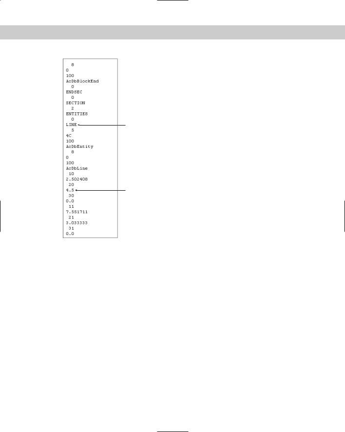
Chapter 27 Working with Other Applications |
839 |
Object
 X coordinate of start point
Y coordinate of start point
 X coordinate of endpoint
 Y coordinate of endpoint
Figure 27-1: Most CAD programs accept the DXF file format.
To create a DXF file, choose File Save As. Choose one of the DXF formats in the Files of Type drop-down list. You can save in DXF formats for Releases 12, 2000, and 2004. The 2005 format interchangeable with the 2004 format so that AutoCAD 2004 and AutoCAD LT 2004 can open AutoCAD 2005 and AutoCAD LT 2005 drawings, and vice versa. Click Save.
Exporting to other file formats
When you want to export a drawing to another file format, whether to create an image file or import that file into another application, you export the drawing. To export a drawing to another format (except for DWF, JPG, PNG, and TIF), follow these steps:
1.Choose File Export to open the Export Data dialog box, shown in Figure 27-2.
2.Choose the file format you want in the Files of Type drop-down list.
3.Find the desired folder using the Save In drop-down list and the Folder box.
4.Click Save.
840 Part V Organizing and Managing Drawings
Figure 27-2: The Export Data dialog box.
To export to JPG, PNG, or TIF formats, use the JPGOUT, PNGOUT, or TIFOUT command on the command line. Then, choose a folder, click Save, and select objects at the prompt.
Controlling the display of exported WMF files
The WMFBKGND system variable controls the background of WMF files that you export, whether using the Export dialog box, copying and pasting, or dragging and dropping. When the value of this system variable is Off (the default), the background color of the file is transparent, so that it doesn’t interfere with the background on which it is pasted. You can set it to On so that the background is the same as that of the drawing background.
The WMFFOREGND system variable works in tandem with the WMFBKGND system variable. It controls the foreground (line) color of objects when you export WMF files. WMFFOREGND takes effect only when you set WMFBKGND to 0, which makes the background color transparent. A value of 0, the default, swaps foreground and background colors, if necessary, to make the foreground color (the objects) darker than the background color. A value of 1 does the opposite — the foreground color is lighter than the background color.
On the |
The drawing used in the following Step-by-Step exercise on exporting a WMF file, |
CD-ROM |
ab27-a.dwg, is in the Drawings folder on the CD-ROM. |

Chapter 27 Working with Other Applications |
841 |
STEP-BY-STEP: Exporting a WMF File
1.Open ab27-a.dwg from the CD-ROM.
2.Save the file as ab27-01.dwg in your AutoCAD Bible folder. You can see it in Figure 27-3.
Figure 27-3: The Easy Cotton Mills logo.
3.Choose File Export. The Files of Type drop-down list should say Metafile (*.wmf). The filename automatically reads ab27-01.wmf.
4.If necessary, locate your AutoCAD Bible folder. Click Save.
5.At the Select objects: prompt, make a window around the red rectangle to include all three objects. End object selection to end the command.
You’ve created a WMF file.
Importing files
For most file formats, choose Insert from the menu and then choose Raster Image or the file type you want to import. Find the file in the dialog box and click Open. In most cases, the command line then prompts you for an insertion point, X and Y scale factors, and a rotation angle, just as for block insertion.
Inserting a DXF file
If someone sends you a file in DXF format, it contains a drawing that was probably created in another CAD program. You can open that drawing in AutoCAD or AutoCAD LT. You can import a DXF file in two ways:
To import a DXF file into a new drawing, use the OPEN command to open a new drawing, choose DXF in the Files of Type drop-down list, choose the DXF file, and click Open.
To insert a DXF file into an existing drawing, choose Insert Block. In the Insert dialog box, click Browse. Then choose DXF in the Files of Type drop-down list, choose the DXF file, and click Open.
On the |
The file used in the following Step-by-Step exercise on importing a WMF file, ab27-01.wmf, |
CD-ROM |
is in the Results folder on the CD-ROM. If you did the previous exercise, you can also find |
|
the file in your AutoCAD Bible folder. |

842 Part V Organizing and Managing Drawings
STEP-BY-STEP: Importing a WMF File
1.Open a new drawing using the acad.dwt or aclt.dwt template.
2.Save the file as ab27-02.dwg in your AutoCAD Bible folder.
3.Choose Insert Windows Metafile.
4.If you did the previous exercise, locate your AutoCAD Bible folder in the Import WMF dialog box. Choose ab27-01.wmf. If you didn’t do the previous exercise, find ab27-01.wmf in the Results folder of the CD-ROM. In the Import WMF dialog box, choose Tools Options. Check Wire Frame (No Fills), uncheck Wide Lines if necessary, and click OK. Click Open.
5.At the Specify insertion point or [Scale/X/Y/Z/Pscale/PX/PY/PZ/Protate]: prompt, pick any point near the top of your screen. Notice that the insertion point is at the top-left corner of the image.
6.Press Enter to accept the defaults for X and Y scales and rotation angle. Notice that you’ve lost the solid fill in the logo. The red rectangle came in fine. Also, you may see an added rectangle around the extents of the image where the extents of the screen were when the WMF file was created.
7.Pick the image. Notice that everything is selected with one grip at the insertion point. Choose Explode from the Modify toolbar.
8.Choose Tools Inquiry List and pick any part of the logo. Press Enter. Notice from the listing that the logo is now made up of polylines. Repeat the LIST command with the text. It has been converted to a TEXT object. (If the text was based on a SHX font, it would be converted to polylines.) Because WMF files convert to drawing objects, you can edit them, but they may require a good deal of cleanup to attain a pleasing result.
9.Choose Insert Windows Metafile. Choose ab27-01.wmf. Click Options to open the Import Options (WMF In) dialog box, as shown in Figure 27-4. This time, check Wide Lines, uncheck Wire Frame, and click OK. In the Import WMF dialog box, click Open to import the file. Pick in a different location in your drawing, and accept the defaults.
10.Explode the inserted image. (You may have to pick it at its edge.) Erase the rectangle and the line at the right that remains. Now you have an image that is very close to the original. The text comes in with the Bookman Old Style font (or the font you used — the same font as the original), although the spacing is not exact. Also, the logo now has its solid fill. It should look like Figure 27-4.
11.Save your drawing.
Figure 27-4: An imported WMF file.