

- •Foreword
- •Preface
- •Is This Book for You?
- •How This Book Is Organized
- •How to Use This Book
- •Doing the Exercises
- •Conventions Used in This Book
- •What the Icons Mean
- •About the CD-ROM
- •Other Information
- •Contacting the Author
- •Acknowledgments
- •Contents at a Glance
- •Contents
- •Getting Acquainted with AutoCAD and AutoCAD LT
- •Starting AutoCAD and AutoCAD LT
- •Creating a New Drawing
- •Using the AutoCAD and AutoCAD LT Interface
- •Creating Your First Drawing
- •Saving a Drawing
- •Summary
- •Creating a New Drawing from a Template
- •Working with Templates
- •Opening a Drawing with Default Settings
- •Opening an Existing Drawing
- •Using an Existing Drawing as a Prototype
- •Saving a Drawing Under a New Name
- •Summary
- •The Command Line
- •Command Techniques
- •Of Mice and Pucks
- •Getting Help
- •Summary
- •Typing Coordinates
- •Displaying Coordinates
- •Picking Coordinates on the Screen
- •Locating Points
- •Summary
- •Unit Types
- •Drawing Limits
- •Understanding Scales
- •Inserting a Title Block
- •Common Setup Options
- •The MVSETUP Command
- •Summary
- •Using the LINE Command
- •Drawing Rectangles
- •Drawing Polygons
- •Creating Construction Lines
- •Creating Rays
- •Summary
- •Drawing Circles
- •Drawing Arcs
- •Creating Ellipses and Elliptical Arcs
- •Making Donuts
- •Placing Points
- •Summary
- •Panning
- •The ZOOM Command
- •Aerial View
- •Named Views
- •Tiled Viewports
- •Snap Rotation
- •User Coordinate Systems
- •Isometric Drawing
- •Summary
- •Editing a Drawing
- •Selecting Objects
- •Summary
- •Copying and Moving Objects
- •Using Construction Commands
- •Creating a Revision Cloud
- •Hiding Objects with a Wipeout
- •Double-Clicking to Edit Objects
- •Grips
- •Editing with the Properties Palette
- •Selection Filters
- •Groups
- •Summary
- •Working with Layers
- •Changing Object Color, Linetype, and Lineweight
- •Working with Linetype Scales
- •Importing Layers and Linetypes from Other Drawings
- •Matching Properties
- •Summary
- •Drawing-Level Information
- •Object-Level Information
- •Measurement Commands
- •AutoCAD’s Calculator
- •Summary
- •Creating Single-Line Text
- •Understanding Text Styles
- •Creating Multiline Text
- •Creating Tables
- •Inserting Fields
- •Managing Text
- •Finding Text in Your Drawing
- •Checking Your Spelling
- •Summary
- •Working with Dimensions
- •Drawing Linear Dimensions
- •Drawing Aligned Dimensions
- •Creating Baseline and Continued Dimensions
- •Dimensioning Arcs and Circles
- •Dimensioning Angles
- •Creating Ordinate Dimensions
- •Drawing Leaders
- •Using Quick Dimension
- •Editing Dimensions
- •Summary
- •Understanding Dimension Styles
- •Defining a New Dimension Style
- •Changing Dimension Styles
- •Creating Geometric Tolerances
- •Summary
- •Creating and Editing Polylines
- •Drawing and Editing Splines
- •Creating Regions
- •Creating Boundaries
- •Creating Hatches
- •Creating and Editing Multilines
- •Creating Dlines
- •Using the SKETCH Command
- •Digitizing Drawings with the TABLET Command
- •Summary
- •Preparing a Drawing for Plotting or Printing
- •Creating a Layout in Paper Space
- •Working with Plot Styles
- •Plotting a Drawing
- •Summary
- •Combining Objects into Blocks
- •Inserting Blocks and Files into Drawings
- •Managing Blocks
- •Using Windows Features
- •Working with Attributes
- •Summary
- •Understanding External References
- •Editing an Xref within Your Drawing
- •Controlling Xref Display
- •Managing Xrefs
- •Summary
- •Preparing for Database Connectivity
- •Connecting to Your Database
- •Linking Data to Drawing Objects
- •Creating Labels
- •Querying with the Query Editor
- •Working with Query Files
- •Summary
- •Working with 3D Coordinates
- •Using Elevation and Thickness
- •Working with the User Coordinate System
- •Summary
- •Working with the Standard Viewpoints
- •Using DDVPOINT
- •Working with the Tripod and Compass
- •Getting a Quick Plan View
- •Shading Your Drawing
- •Using 3D Orbit
- •Using Tiled Viewports
- •Defining a Perspective View
- •Laying Out 3D Drawings
- •Summary
- •Drawing Surfaces with 3DFACE
- •Drawing Surfaces with PFACE
- •Creating Polygon Meshes with 3DMESH
- •Drawing Standard 3D Shapes
- •Drawing a Revolved Surface
- •Drawing an Extruded Surface
- •Drawing Ruled Surfaces
- •Drawing Edge Surfaces
- •Summary
- •Drawing Standard Shapes
- •Creating Extruded Solids
- •Drawing Revolved Solids
- •Creating Complex Solids
- •Sectioning and Slicing Solids
- •Using Editing Commands in 3D
- •Editing Solids
- •Listing Solid Properties
- •Summary
- •Understanding Rendering
- •Creating Lights
- •Creating Scenes
- •Working with Materials
- •Using Backgrounds
- •Doing the Final Render
- •Summary
- •Accessing Drawing Components with the DesignCenter
- •Accessing Drawing Content with Tool Palettes
- •Setting Standards for Drawings
- •Organizing Your Drawings
- •Working with Sheet Sets
- •Maintaining Security
- •Keeping Track of Referenced Files
- •Handling Errors and Crashes
- •Managing Drawings from Prior Releases
- •Summary
- •Importing and Exporting Other File Formats
- •Working with Raster Images
- •Pasting, Linking, and Embedding Objects
- •Summary
- •Sending Drawings
- •Opening Drawings from the Web
- •Creating Object Hyperlinks
- •Publishing Drawings
- •Summary
- •Working with Customizable Files
- •Creating Keyboard Shortcuts for Commands
- •Customizing Toolbars
- •Customizing Tool Palettes
- •Summary
- •Creating Macros with Script Files
- •Creating Slide Shows
- •Creating Slide Libraries
- •Summary
- •Creating Linetypes
- •Creating Hatch Patterns
- •Summary
- •Creating Shapes
- •Creating Fonts
- •Summary
- •Working with Menu Files
- •Customizing a Menu
- •Summary
- •Introducing Visual LISP
- •Getting Help in Visual LISP
- •Working with AutoLISP Expressions
- •Using AutoLISP on the Command Line
- •Creating AutoLISP Files
- •Summary
- •Creating Variables
- •Working with AutoCAD Commands
- •Working with Lists
- •Setting Conditions
- •Managing Drawing Objects
- •Getting Input from the User
- •Putting on the Finishing Touches
- •Summary
- •Understanding Local and Global Variables
- •Working with Visual LISP ActiveX Functions
- •Debugging Code
- •Summary
- •Starting to Work with VBA
- •Writing VBA Code
- •Getting User Input
- •Creating Dialog Boxes
- •Modifying Objects
- •Debugging and Trapping Errors
- •Moving to Advanced Programming
- •A Final Word
- •Installing AutoCAD and AutoCAD LT
- •Configuring AutoCAD
- •Starting AutoCAD Your Way
- •Configuring a Plotter
- •System Requirements
- •Using the CD with Microsoft Windows
- •What’s on the CD
- •Troubleshooting
- •Index

Chapter 15 Creating Dimension Styles and Tolerances |
399 |
Note The Vertical position setting also applies to stacked fractions, determining how the fractions are justified with the whole-number dimensions.
Use the Zero Suppression section to suppress leading or trailing zeros, or feet and inches. See the preceding explanation of the Primary Units tab for more information.
If you’ve turned on alternate units, you can separately set the precision and zero suppression for alternate unit tolerances in the Precision text box.
Click OK, and then click Close to return to your drawing. You’re ready to start dimensioning!
Changing Dimension Styles
Just as you often need to edit objects in a drawing, you may need to edit dimension styles. Whether you want to use a different dimension style for a certain object or change the properties of a dimension style, you have the flexibility you need. You can change dimensions in the following ways:
Choose a new dimension style.
Create a variant of a dimension style for a certain type of dimension.
Modify the characteristics of the dimension style in use.
Override the dimension style with different dimension options for one dimension that you want to be an exception.
Chapter 14 covers some dimension editing techniques. This section explains how to make changes related to dimension styles.
Choosing a new current dimension style
To start using another dimension style, click the Dim Style Control drop-down list on the Styles toolbar or the Dimension toolbar and choose the dimension style that you want to use.
Existing dimensions remain unchanged, but any new dimensions you add from this point forward will use the new current dimension style.
Creating a variant of a dimension style
Create a variant of a dimension style for a specific type of dimension, such as a leader or angular dimension. You might have an architectural dimension style with ticks (rather than arrows) at the end of the dimension lines, but you might want angular dimensions to have open arrows. Here are the steps:
1.Choose Dimension Style from the Dimension toolbar.
2.Click New.
3.From the Use For drop-down list, choose the type of dimension that you want to use with the new variant.
4.Click Continue.
400 Part II Drawing in Two Dimensions
5.Make the changes you want, using the techniques described earlier in this chapter.
6.Click OK to return to the Dimension Style Manager. Here you see the variant listed under its base (parent) dimension style.
7.Click Close.
Dimensions of the type you specified now take on the characteristics of the variant. For example, angular dimensions would have an open arrow.
|
Modifying a dimension to use a new dimension style |
|
You can change the dimension style used by a dimension. Select the dimension and then |
|
choose a new dimension style from the Dim Style Control drop-down list on the Styles or |
|
Dimension toolbar. |
|
Another method of changing a dimension’s style is to choose Properties on the Standard tool- |
|
bar and select one or more dimensions. In the Properties palette, click the Dim style item in |
|
the Misc section and choose a new dimension style from the drop-down list. |
Tip |
Double-click any dimension to open the Properties palette where you can change the prop- |
|
erties of that dimension. |
You can choose Match Properties on the Standard toolbar to match the properties of one dimension to those of another. Follow these steps:
1.Choose Match Properties.
2.At the Select source object: prompt, choose the dimension whose properties you want to copy.
3.At the Select destination object(s) or [Settings]: prompt, choose the dimension or dimensions you want to copy the properties to. (Use the Settings option if you only want to copy some of the properties.)
4.Press Enter to end the command.
Modifying dimension styles
You can easily change a dimension style. The advantage of changing a dimension style is that all dimensions using that style are automatically updated. To change a style:
1.Choose Dimension Style from the Dimension toolbar.
2.Choose the dimension style you want to change from the list of styles.
3.Choose Modify.
4.AutoCAD opens the Modify Dimension Style dialog box, which is exactly the same as the New Dimension Style dialog box. Use the settings on all the tabs and make the changes you want. Click OK to close these dialog boxes and return to the Dimension Styles Manager.
5.Click Close.

Chapter 15 Creating Dimension Styles and Tolerances |
401 |
All dimensions automatically change to reflect the changed dimension style.
Tip You can create a new dimension style from an existing dimension on the fly by using the Properties palette. Double-click a dimension to open the Properties palette. Click the arrow next to the type of change you want to make and make the change. After you’re done, rightclick in the drawing area and choose Dim Style Save as New Style. The New Dimension Style dialog box opens so that you can give the dimension style a name. Click OK.
Overriding a dimension style
Sometimes you want to make an exception to a style for one dimension — for example, when suppressing an extension line in a tight space. It isn’t often worthwhile to create a new dimension style for such a situation. To override a dimension style, simply change the properties of the dimension by using the Properties palette.
You can also create an override to the current dimension style. The override is like a subset of the dimension style. After you create the override, all new dimensions you create using the dimension style include the override changes. To revert back to the original dimension style, you must delete the override. You also have the option to incorporate the override into the dimension style or save it as a new style.
To create a dimension style override, follow these steps:
1.Choose Dimension Style from the Dimension toolbar.
2.Choose the dimension style for which you want to create an override (if it isn’t already selected).
3.In the Dimension Style Manager, click Override.
4.The Override dialog box opens, which is just like the New (or Modify) Dimension Style dialog box. Make the changes you want using any of the tabs. Click OK.
5.In the Dimension Style Manager, you see the style override listed beneath the dimension style you selected. Click Close.
New dimensions that you create using the dimension style you selected now include the override properties.
To stop using the override, open the Dimension Style Manager, right-click the style override to open the shortcut menu, and do one of the following:
Choose Delete to delete the override.
Choose Save to Current Style to incorporate the override properties into the current dimension style.
Choose Rename to create a new dimension style from the override. You see a selection box around the name. Type a new dimension style name and press Enter. This action removes the override and replaces it with the new dimension style.
Removing the override doesn’t change dimensions that you’ve already created with the override.

402 Part II Drawing in Two Dimensions
Dimension system variables
All the settings you make in the Dimension Styles dialog box are stored in a large number of system variables devoted to dimensions. (See Chapter 5 for more information about system variables).
To read about the dimension variables, choose Help Help and click the Contents tab. Doubleclick Command Reference and then double-click System Variables. Double-click D System Variables. All the variables starting with DIM are dimension system variables.
Once upon a time, the only way to manage dimensions was by knowing all the dimension system variables and individually setting each one. Today, the Dimension Style Manager makes managing dimensions much easier. However, if you want to create scripts or AutoLISP routines to manage your dimensions, you need to understand how the dimension system variables work because scripts and AutoLISP routines cannot access dialog boxes.
You can use the DIMSTYLE command on the command line to list all the system variable settings for a dimension style. Type -dimstyle at the command line. Use the STatus option to display the current style’s system variable values. You can get a great education in dimension system variables by printing out and perusing this list.
The other DIMSTYLE options are:
Save: Saves a dimension style.
Restore: Makes a dimension style current.
Variables: Lists dimension variables, such as the STatus option, but lets you first choose which dimension style you want to list the variables for.
Apply: Updates dimensions to the current style, including overrides. This is equivalent to choosing Update from the Dimension toolbar.
?: Lists all dimension styles in the drawing.
You can also create dimension style overrides by using the DIMOVERRIDE command (Dimension Override). You need to know the name of the system variable and the setting code you want. The command displays the Enter dimension variable name to override (or Clear overrides): prompt. To create an override, type the system variable and its setting. Then select the dimensions for which you want to override dimension style settings. To clear all dimension style overrides, type c . Then select the dimensions for which you want to remove overrides.
Updating dimensions
The Dimension toolbar includes an Update button. This command updates selected dimensions so that they use the current dimension style, including any overrides you may have just made. Use this when you realize that you want to include some existing dimensions in the overrides you’ve made.
Comparing dimension styles
You can compare a dimension style with the current dimension style. To do this, follow these steps:
Chapter 15 Creating Dimension Styles and Tolerances |
403 |
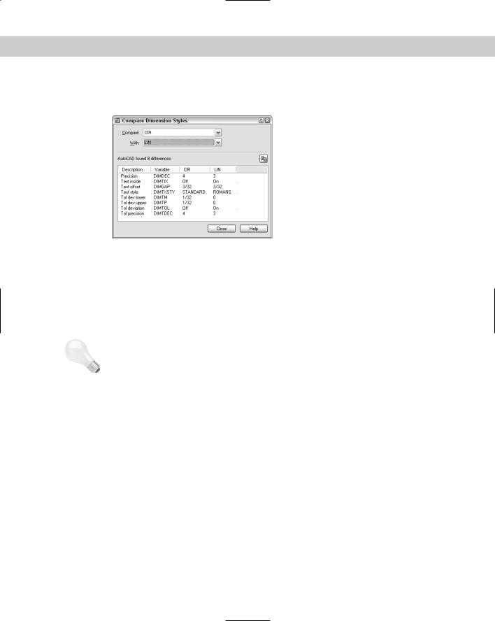
1.Choose Dimension Style from the Dimension toolbar and choose Compare. The Compare Dimension Styles dialog box (shown in Figure 15-32) opens.
Figure 15-32: The Compare Dimension Styles dialog box enables you to compare the properties of two dimension styles.
2.In the Compare and With drop-down boxes, choose the two dimension styles you want to compare. The resulting list shows the differences by system variable. For more information about system variables used in dimensions, see the sidebar, “Dimension system variables.”
3.Click Close twice to return to your drawing.
Tip |
Click the Copy button at the right side of the Compare Dimension Styles dialog box to copy the |
|
comparison to the Clipboard. You can then paste it into another document (for example, an |
|
e-mail message to a client). |
Copying dimension styles from other drawings
With proper planning, dimension styles make dimensioning much easier and produce moreuniform results. Although you can save dimension styles in your templates, you may sometimes need to work with someone else’s drawing or an old drawing that doesn’t contain the dimension styles you need. As explained in Chapters 11 and 13, you can use the DesignCenter to import features from other drawings. To import a dimension style, follow these steps:
1.Choose DesignCenter from the Standard toolbar to open the DesignCenter.
2.In the left pane, navigate to the drawing that has the dimension style you want.
3.Double-click the drawing icon or click its plus sign.
4.To see the list of the dimension styles, double-click the dimension style’s icon in either the left or right pane.
5.Double-click the dimension style’s icon to import it into your drawing.
6.If you want, click the DesignCenter’s Close button to close the DesignCenter.
404 Part II Drawing in Two Dimensions
On the
CD-ROM
The Express Tools offer two commands, DIMIM and DIMEX, which enable you to save (export) and retrieve (import) dimension styles. Choose Express Dimension Dimstyle Import or Dimstyle Export. For information on installing Express Tools, see Appendix A.
The drawing used in the following Step-by-Step exercise on changing dimension styles, ab15- b.dwg, is in the Drawings folder on the CD-ROM.
STEP-BY-STEP: Changing Dimension Styles
1.Open ab15-b.dwg from your CD-ROM.
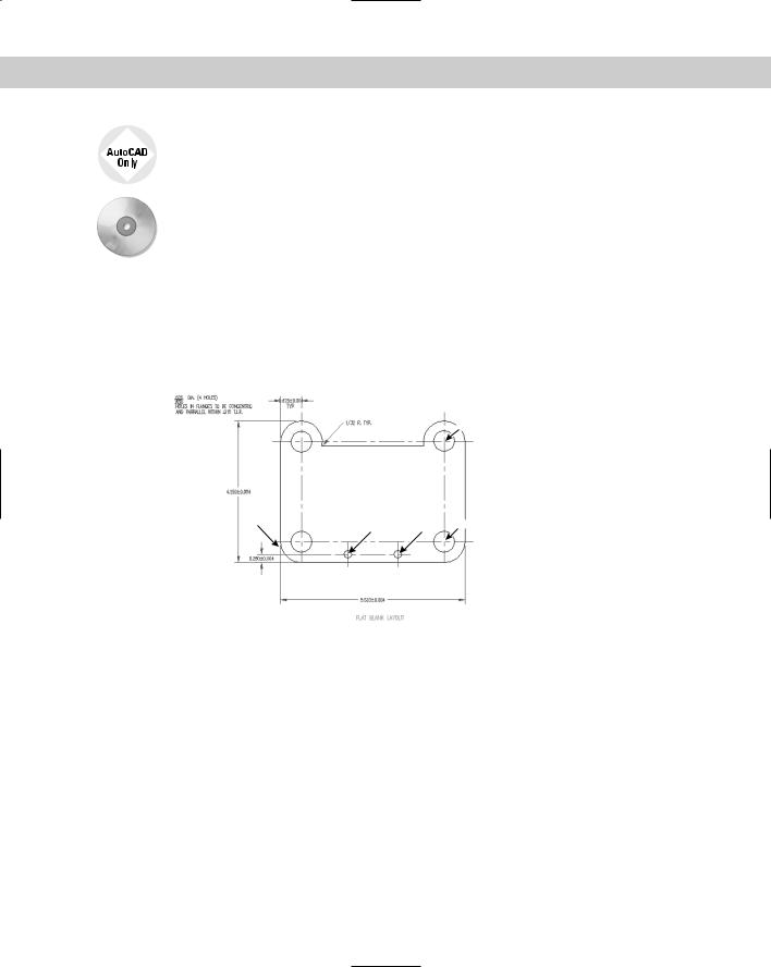
2.Save the file as ab15-05.dwg in your AutoCAD Bible folder. This is a tension arm for a commercial dryer, as shown in Figure 15-33. ORTHO and OSNAP should be on. Set running object snaps for endpoint, intersection, and center. The Dims layer is current. If the Dimension toolbar is not visible, right-click any toolbar and choose Dimension.
4
1 |
2 |
3 |
5 |
|
Figure 15-33: The tension arm needs some additional dimensions.
3.The current dimension style is CIR. From the Dim Style Control drop-down list on the Dimension toolbar, choose LIN.
4.Choose Linear Dimension from the Dimension toolbar. At the Specify first
extension line origin or <select object>: prompt, choose the endpoint at
1 in Figure 15-33. (If necessary, press Tab until you see the endpoint tooltip.) At the
Specify second extension line origin: prompt, choose the intersection at 2. At the Specify dimension line location or [Mtext/Text/Angle/Horizontal/ Vertical/Rotated]: prompt, choose an appropriate location above the bottom-most dimension.
5.Choose Dimension Style from the Dimension toolbar. Choose Override and click the Tolerances tab. Change the Tolerance Method to None. Click the Lines and Arrows tab. In the Extension Lines section, check Suppress Ext Line 1 to suppress the first extension line. Click OK. In the Dimension Style Manager, click Close.
Chapter 15 Creating Dimension Styles and Tolerances |
405 |
6. Choose Linear Dimension from the Dimension toolbar. At the Specify first extension line origin or <select object>: prompt, choose the intersection at 2 in Figure 15-33. At the Specify second extension line origin: prompt, choose the intersection at 3. At the Specify dimension line location or [Mtext/Text/ Angle/Horizontal/Vertical/Rotated]: prompt, pick the endpoint object snap at the right side of the previous dimension’s dimension line in order to align the two dimensions.
7.The first dimension (the one you created in Step 4) needs to be updated to remove the tolerance. Choose Dimension Update from the Dimension toolbar. At the Select objects: prompt, choose the first dimension. Right-click to end object selection to update the dimension.
8.To list the overrides, choose Dimension Style from the Dimension toolbar. Choose Compare. In the Compare Dimension Styles dialog box, <style overrides> should be displayed in the Compare drop-down list, and LIN should be displayed in the With drop-down list. You see a list of the overrides, which are the only differences between the two. Click Close.
9.To remove the overrides (no tolerance and the first extension line suppressed), rightclick <style overrides> in the Dimension Style Manager and choose Delete. You get
the message, Are you sure you want to delete ‘<style overrides>’? Choose Yes. Click Close to return to the drawing.
10. Choose Linear Dimension from the Dimension toolbar. At the Specify first extension line origin or <select object>: prompt, choose the intersection at 4 in Figure 15-33. At the Specify second extension line origin: prompt, choose the intersection at 5. At the Specify dimension line location or [Mtext/Text/ Angle/Horizontal/Vertical/Rotated]: prompt, pick an appropriate location to the right of the model.
11.To compare the CIR and LIN dimension styles, choose Dimension Style from the Dimension toolbar. Choose Compare. LIN should appear in the Compare drop-down list. Choose CIR from the With drop-down list. The result is a list of the differences. Click Close twice to return to your drawing.
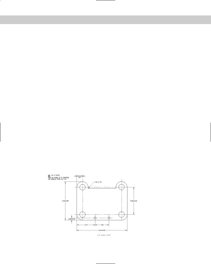
12.Save your drawing. It should look like Figure 15-34.
Figure 15-34: The dimensions have been added.