

- •Foreword
- •Preface
- •Is This Book for You?
- •How This Book Is Organized
- •How to Use This Book
- •Doing the Exercises
- •Conventions Used in This Book
- •What the Icons Mean
- •About the CD-ROM
- •Other Information
- •Contacting the Author
- •Acknowledgments
- •Contents at a Glance
- •Contents
- •Getting Acquainted with AutoCAD and AutoCAD LT
- •Starting AutoCAD and AutoCAD LT
- •Creating a New Drawing
- •Using the AutoCAD and AutoCAD LT Interface
- •Creating Your First Drawing
- •Saving a Drawing
- •Summary
- •Creating a New Drawing from a Template
- •Working with Templates
- •Opening a Drawing with Default Settings
- •Opening an Existing Drawing
- •Using an Existing Drawing as a Prototype
- •Saving a Drawing Under a New Name
- •Summary
- •The Command Line
- •Command Techniques
- •Of Mice and Pucks
- •Getting Help
- •Summary
- •Typing Coordinates
- •Displaying Coordinates
- •Picking Coordinates on the Screen
- •Locating Points
- •Summary
- •Unit Types
- •Drawing Limits
- •Understanding Scales
- •Inserting a Title Block
- •Common Setup Options
- •The MVSETUP Command
- •Summary
- •Using the LINE Command
- •Drawing Rectangles
- •Drawing Polygons
- •Creating Construction Lines
- •Creating Rays
- •Summary
- •Drawing Circles
- •Drawing Arcs
- •Creating Ellipses and Elliptical Arcs
- •Making Donuts
- •Placing Points
- •Summary
- •Panning
- •The ZOOM Command
- •Aerial View
- •Named Views
- •Tiled Viewports
- •Snap Rotation
- •User Coordinate Systems
- •Isometric Drawing
- •Summary
- •Editing a Drawing
- •Selecting Objects
- •Summary
- •Copying and Moving Objects
- •Using Construction Commands
- •Creating a Revision Cloud
- •Hiding Objects with a Wipeout
- •Double-Clicking to Edit Objects
- •Grips
- •Editing with the Properties Palette
- •Selection Filters
- •Groups
- •Summary
- •Working with Layers
- •Changing Object Color, Linetype, and Lineweight
- •Working with Linetype Scales
- •Importing Layers and Linetypes from Other Drawings
- •Matching Properties
- •Summary
- •Drawing-Level Information
- •Object-Level Information
- •Measurement Commands
- •AutoCAD’s Calculator
- •Summary
- •Creating Single-Line Text
- •Understanding Text Styles
- •Creating Multiline Text
- •Creating Tables
- •Inserting Fields
- •Managing Text
- •Finding Text in Your Drawing
- •Checking Your Spelling
- •Summary
- •Working with Dimensions
- •Drawing Linear Dimensions
- •Drawing Aligned Dimensions
- •Creating Baseline and Continued Dimensions
- •Dimensioning Arcs and Circles
- •Dimensioning Angles
- •Creating Ordinate Dimensions
- •Drawing Leaders
- •Using Quick Dimension
- •Editing Dimensions
- •Summary
- •Understanding Dimension Styles
- •Defining a New Dimension Style
- •Changing Dimension Styles
- •Creating Geometric Tolerances
- •Summary
- •Creating and Editing Polylines
- •Drawing and Editing Splines
- •Creating Regions
- •Creating Boundaries
- •Creating Hatches
- •Creating and Editing Multilines
- •Creating Dlines
- •Using the SKETCH Command
- •Digitizing Drawings with the TABLET Command
- •Summary
- •Preparing a Drawing for Plotting or Printing
- •Creating a Layout in Paper Space
- •Working with Plot Styles
- •Plotting a Drawing
- •Summary
- •Combining Objects into Blocks
- •Inserting Blocks and Files into Drawings
- •Managing Blocks
- •Using Windows Features
- •Working with Attributes
- •Summary
- •Understanding External References
- •Editing an Xref within Your Drawing
- •Controlling Xref Display
- •Managing Xrefs
- •Summary
- •Preparing for Database Connectivity
- •Connecting to Your Database
- •Linking Data to Drawing Objects
- •Creating Labels
- •Querying with the Query Editor
- •Working with Query Files
- •Summary
- •Working with 3D Coordinates
- •Using Elevation and Thickness
- •Working with the User Coordinate System
- •Summary
- •Working with the Standard Viewpoints
- •Using DDVPOINT
- •Working with the Tripod and Compass
- •Getting a Quick Plan View
- •Shading Your Drawing
- •Using 3D Orbit
- •Using Tiled Viewports
- •Defining a Perspective View
- •Laying Out 3D Drawings
- •Summary
- •Drawing Surfaces with 3DFACE
- •Drawing Surfaces with PFACE
- •Creating Polygon Meshes with 3DMESH
- •Drawing Standard 3D Shapes
- •Drawing a Revolved Surface
- •Drawing an Extruded Surface
- •Drawing Ruled Surfaces
- •Drawing Edge Surfaces
- •Summary
- •Drawing Standard Shapes
- •Creating Extruded Solids
- •Drawing Revolved Solids
- •Creating Complex Solids
- •Sectioning and Slicing Solids
- •Using Editing Commands in 3D
- •Editing Solids
- •Listing Solid Properties
- •Summary
- •Understanding Rendering
- •Creating Lights
- •Creating Scenes
- •Working with Materials
- •Using Backgrounds
- •Doing the Final Render
- •Summary
- •Accessing Drawing Components with the DesignCenter
- •Accessing Drawing Content with Tool Palettes
- •Setting Standards for Drawings
- •Organizing Your Drawings
- •Working with Sheet Sets
- •Maintaining Security
- •Keeping Track of Referenced Files
- •Handling Errors and Crashes
- •Managing Drawings from Prior Releases
- •Summary
- •Importing and Exporting Other File Formats
- •Working with Raster Images
- •Pasting, Linking, and Embedding Objects
- •Summary
- •Sending Drawings
- •Opening Drawings from the Web
- •Creating Object Hyperlinks
- •Publishing Drawings
- •Summary
- •Working with Customizable Files
- •Creating Keyboard Shortcuts for Commands
- •Customizing Toolbars
- •Customizing Tool Palettes
- •Summary
- •Creating Macros with Script Files
- •Creating Slide Shows
- •Creating Slide Libraries
- •Summary
- •Creating Linetypes
- •Creating Hatch Patterns
- •Summary
- •Creating Shapes
- •Creating Fonts
- •Summary
- •Working with Menu Files
- •Customizing a Menu
- •Summary
- •Introducing Visual LISP
- •Getting Help in Visual LISP
- •Working with AutoLISP Expressions
- •Using AutoLISP on the Command Line
- •Creating AutoLISP Files
- •Summary
- •Creating Variables
- •Working with AutoCAD Commands
- •Working with Lists
- •Setting Conditions
- •Managing Drawing Objects
- •Getting Input from the User
- •Putting on the Finishing Touches
- •Summary
- •Understanding Local and Global Variables
- •Working with Visual LISP ActiveX Functions
- •Debugging Code
- •Summary
- •Starting to Work with VBA
- •Writing VBA Code
- •Getting User Input
- •Creating Dialog Boxes
- •Modifying Objects
- •Debugging and Trapping Errors
- •Moving to Advanced Programming
- •A Final Word
- •Installing AutoCAD and AutoCAD LT
- •Configuring AutoCAD
- •Starting AutoCAD Your Way
- •Configuring a Plotter
- •System Requirements
- •Using the CD with Microsoft Windows
- •What’s on the CD
- •Troubleshooting
- •Index
Chapter 20 Working with External Databases |
577 |
Figure 20-14: The horizontal angle.
9.In the drawing, press Esc to deselect the objects and remove the grips. To check the link, click any other row in the Data View window to move the cursor. (Try to position the Data View window so that you can see both the row you were working with and the objects you linked it to at the same time.) Choose Data View View Linked Records. At the Select objects: prompt, select one of the objects in the angle and press Enter. AutoCAD displays the correct row in the database.
10.Save your drawing and keep it open for the next exercise.
Creating Labels
A label is multiline text that appears in your drawing, displaying data from a row in your database. You can choose which fields from the row are displayed. There are two types of labels:
Attached labels are attached to objects and are displayed with a leader pointing to the object. If you move the object, the label moves as well. Use an attached label when the row in the database applies to one or more specific objects in your drawing.
Freestanding labels are independent of any object. You would use freestanding labels when your database applies to the drawing as a whole.
Creating label templates
Before creating a label, you need to create a label template. A label template specifies which fields will be included in the label as well as text formatting. Here’s how to create a label template:
1.Choose dbConnect Templates New Label Template.
2.In the Select a Database Object dialog box, choose a link template to use with the label template. Click Continue.
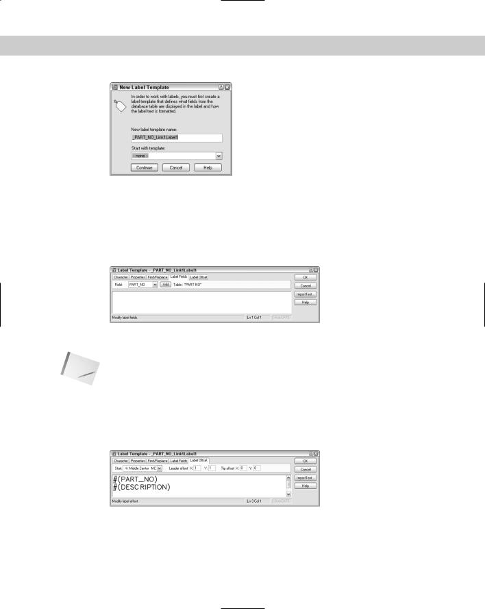
3.In the New Label Template dialog box, shown in Figure 20-15, type a template name in the New Label Template Name text box. AutoCAD suggests a default name. If you have an existing label template you would like to use as a basis for the new label template, choose it from the Start with Template drop-down list. Click Continue.
578 Part III Working with Data
Figure 20-15: The New Label Template dialog box.
4.AutoCAD opens the Label Template dialog box, shown in Figure 20-16, with the Label Fields tab displayed. Use the Character and Properties tabs to format the text. (Note that this dialog box looks like the pre-2004 Multiline Text Editor.)
5.On the Label Fields tab, choose a field that you want to appear on the label from the Field drop-down list. Then click Add. Continue to add fields as desired. You can add text to this field. For example, you could type Part No: before the PART_NO field.
|
Figure 20-16: Use the Label Template dialog box to format |
|
and define label templates. |
Note |
If you add text before or after the field, don’t forget to add a space between the text and the |
|
field so that the result is Part No: 9003-242-001 rather than Part No:9003-242-001, for |
|
example. |
6.Click the Label Offset tab, shown in Figure 20-17. This tab defines the placement of the label and the leader that connects the label with the object. In the Start drop-down list, choose a justification. This defines where on the object AutoCAD places the tip of the leader.
Figure 20-17: The Label Offset tab of the Label Template dialog box.
7.In the Leader Offset text boxes, type an X and Y offset (in units). This offset represents the X and Y distances between the point of the leader arrow and the insertion point of the text. (If this distance is too small to fit an arrow, the arrow is suppressed.)

Chapter 20 Working with External Databases |
579 |
8.In the Tip Offset text boxes, type an X and Y offset (in units). This offset represents the distance between the point of the leader arrow and the object it points to. By default, this is set to 0,0 so that the point of the leader arrow touches its object.
9.Click OK to close the Label Template dialog box and place the label.
After you create the label template, you can create attached and freestanding labels. The settings on the Label Offset tab apply only to attached labels.
You can edit a label template to change the included fields or the formatting. To edit a label template, choose dbConnect Templates Edit Label Template. In the Select a Database Object dialog box, choose the label template you want to edit and click Continue. Then use the Label Template dialog box to edit the label template using the same steps you used to create it. Click OK after you’re done.
Creating attached labels
You create a link between a row and an object and an associated attached label at the same time. You need to have a table open and to have defined both a link and a label template. If you have defined more than one link or label template, choose the desired template(s) from the drop-down list at the top of the Data View window. Follow these steps:
1.Select the record you want to link by clicking its row header in the Data View window.
2.Choose Data View Link and Label Settings Create Attached Labels. This puts you in Creating Attached Labels mode, which means that from now on any links you create also create labels.
3.Choose Data View Link.
4.At the Select objects: prompt, choose the object(s) you want to attach to the label. End object selection.
5.AutoCAD automatically places the label based on the label template. If you selected more than one object, labels are placed on all the objects (which can get confusing).
Of course, you can then move the labels and leaders to a more suitable location.
If you’ve already created a link to an object, follow the same procedure. The link is re-created along with the attached label.
Creating freestanding labels
To create a freestanding label, you need to have a table open with at least a link and a label template. If you have more than one template defined, choose the one you want to use in the drop-down list at the top of the Data View window. Follow these steps:
1.Select the record that you want to link to the freestanding label.
2.Choose Data View Link and Label Settings Create Freestanding Labels.
3.Choose Data View Link.
4.At the Specify point for label: prompt, pick a point in your drawing. AutoCAD places the freestanding label and displays this message on the command line: 1 Record(s) linked with 1 Label(s).
580 Part III Working with Data
When you create a freestanding label, the row and the label are linked. If you select a row linked to a freestanding label and choose Data View View Linked Objects, AutoCAD selects the label.
If the data in the database is changed from within the DBMS, the labels in your drawing may become outdated. To ensure that your labels are always accurate, you should periodically update them. To update labels, choose dbConnect Labels Reload Labels. In the Select a Database Object dialog box, choose the label template you want to use and click OK.
STEP-BY-STEP: Creating a Label Template and a Label
1.Continue with ab20-01.dwg from the previous exercise. The Data View window should still be open. Press Esc to make sure no objects are still selected.
2.Choose dbConnect Templates New Label Template.
3.In the Select a Database Object dialog box, click Continue.
4.In the New Label Template dialog box, click Continue to use the default name.
5.In the Label Template dialog box, click the Label Fields tab. Choose PART_NO from the Field drop-down list. Click Add.
6.Choose DESCRIPTION from the Field drop-down list and click Add.
7.Click the Label Offset tab. In the Start drop-down list, choose Top Left. Set the Leader offset X and Y values to 2.
8.Click the Character tab. Select all the text and change the height to 5⁄16.
9.Click OK.
10.Choose Data View Link and Label Settings Create Attached Labels.
11.Choose Data View Link.
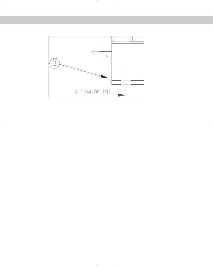
12.At the Select objects: prompt, choose the horizontal line marked at the top of the angle that you linked in the previous exercise. Press Enter to end object selection. AutoCAD automatically places the label.
13.The label covers existing objects. Pick the text of the label and then click its grip. Move the text to the left and pick a better location. The leader automatically changes direction and ends at the left side.
14.Save your drawing. Leave it open for the next Step-by-Step exercise.
Querying with the Query Editor
You can use SQL (Structured Query Language) statements to gather more information about the elements in the drawing and database files. SQL is the language used by almost all database-management systems for refining the information you get from a database.
AutoCAD uses the Query Editor to enable you to design queries. For example, you can do the following:
Query the contents of a database to view a specified subset of the data
View a subset of records that falls into a certain range of values
Access all the tables in one data source with a series of SQL commands

Chapter 20 Working with External Databases |
581 |
In addition, the Link Select dialog box enables you to create a selection set of objects by combining SQL queries and direct selection of objects in your drawing.
To open the Query Editor, follow these steps:
1.Choose dbConnect Queries New Query on a Link Template. (You can also rightclick the table in the dbConnect Manager and choose New Query.)
2.In the Select a Database Object dialog box, choose the link template you want to use and click Continue.
3.In the New Query dialog box (shown in Figure 20-18), type a name for the new query or accept the name AutoCAD supplies. To base a query on an existing query, choose an existing query from the drop-down list. Click Continue.
Figure 20-18: The New Query dialog box.
AutoCAD opens the Query Editor, shown in Figure 20-19. The Query Editor is designed to provide something for everyone — whether you’re just starting out or you’re an expert at SQL.
To restore the original view in the Data View window, do one of the following:
Close the Data View window and then reopen it from the dbConnect window.
Click the Query Builder tab and right-click any used cell. Choose Clear Grid. Click Yes at the warning message. Then click Execute.
Figure 20-19: The Query Editor’s four tabs enable you to build queries to refine how you view your database.

582 Part III Working with Data
Using the Quick Query tab
Use the Quick Query tab to create simple queries based on one field, an operator, and a single value. For example, you can create a query that finds all records from the current table where the field DWG_SIZE equals E. You can also find all records where DWG_SIZE does not equal E.
The advantage to using Quick Query over the Find dialog box, described earlier in this chapter, is that Quick Query displays all the records matching the query and hides the rest. You don’t have to click Find Next to move from record to record.
From the Field box, choose a field. In the Operator drop-down list, choose an operator, such as equal (=) or greater than (>). In the Value box, type a value for the field. If you’re not sure what values are available, click Look Up Values. (This can be slow in a large database or when you’re working with a database across a busy network.)
Caution |
Queries are case-sensitive. A value of “B” is not the same as “b.” You need to be aware of the |
|
case used in your database. Some databases are all uppercase, making it easy to specify val- |
|
ues. Just turn on Caps Lock and type away. |
Choose Indicate Records in Data View and/or Indicate Objects in Drawing. By default, both are checked. To save the query for future use, click Store. Click Execute to see the results.
To return to the Query Editor, choose Return to Query on the Data View window toolbar.
Table 20-2 lists the available operators.
|
Table 20-2: Query Operators |
|
|
Operator |
Description |
|
|
Equal (=) |
Records that match the value exactly. |
Not equal (<>) |
All records except those that match the value exactly. |
Greater than (>) |
Records greater than the value. Includes text. For example, D is greater |
|
than B. |
Less than (<)
Greater than or equal (>=) Less than or equal (<=) Like
Records less than the value.
Records that are greater than or match exactly the value.
Records that are less than or match exactly the value.
Records that contain the value. You must use the % wildcard (which is like the * wildcard used in Windows).
In |
Records that match the values you specify. You list the values, separated |
|
by a comma. For example, you could find records for which the field |
|
DWG_SIZE is B or D by typing B,D in the value box. |
Is null |
Records that have no value. The value box is unavailable. You can use |
|
this to find missing data. |
Is not null |
Records that have a value. You can use this to remove from view all |
|
records with missing data. |
|
|

Chapter 20 Working with External Databases |
583 |
Using the Range Query tab
The Range Query tab, shown in Figure 20-20, finds records based on one field and a range of values. For example, you can find all records where the field DWG_SIZE ranges from B to D. The range can be either textual or numeric.
To construct a range query, choose a field from the Fields list. Then type the beginning value of the range in the From box and the ending value of the range in the Through box. In both cases, you can click Look Up Values to choose from a list.
Click Store to save the query. Click Execute to execute the query.
Figure 20-20: Use the Range Query tab to find records that match a range of values.
Using the Query Building tab
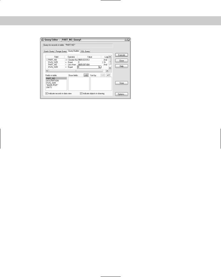
The Query Builder enables you to create multiple criteria. For example, you can create a query that finds records where the field DWG_SIZE ranges from B to D and the field PART_NO is greater than 9029-072-001. In order to build the criteria, you use Boolean operators and parenthetical grouping. This tab also enables you to specify which fields will appear in the Data View window and to sort the records. Using all these options offers a great deal of flexibility to create a complex query without knowing SQL. Here’s how it works:
And operator: Displays the records that meet both the criteria before and after the And operator.
Or operator: Displays records that meet either of the criteria before and after the Or operator.
Parenthetical grouping: Enables you to group sets of criteria. For example, you can group two criteria that use an And operator and a second group of two criteria that use an And operator. Then you can put an Or operator between the two groups.
Figure 20-21 shows an example of a query using all three elements.
584 Part III Working with Data
Figure 20-21: Use the Query Builder tab to design a query with multiple criteria.
Building a query with multiple criteria
To create a query using multiple criteria, follow these steps:
1.On the first line, choose a field from the Field column. (When you click the first cell in the Field column, a drop-down arrow appears.)
2.Choose an Operator from the Operator column.
3.Type a value in the Value cell. (An ellipsis button appears, and you can choose from all the values in the database.)
4.Click in the Logical cell to insert the And operator. Clicking again changes the operator to Or.
5.Move to the second line and create the next row of criteria. Continue until you’ve specified all the criteria you want.
6.Add parenthetical grouping. Click to the left of the Field column of a row to insert a left parenthesis and between the Value and Logical columns to insert a right parenthesis. Continue to insert all the parentheses you need. You can’t insert parentheses until you have enough rows defined for a parenthesis to make sense.
7.Click Store to save the query. Click Execute to execute the Query.
Specifying fields and sorting
You can also limit which fields appear in the Data View table. First define the query in the top half of the tab. The query does not need to be complex. Then select the first field from the Fields in Table list. Click Add above the Show Fields list. Continue until you have all the fields you want. By default, all the fields are shown. To start from scratch, right-click in the Show fields box and choose Clear All. To remove one field, right-click it and choose Clear Field Name.
To sort the data, choose the first field that you want to sort by from the Show Fields list. (You can only sort by fields that you’re showing.) Click Add above the Sort By list. By default, AutoCAD sorts by ascending order. To sort by descending order, click the Ascending/Descending button. You can click it again to change the order back to ascending. You can also repeat the process for additional fields.
Click Store to save the query. Click Execute to execute the Query.

Chapter 20 Working with External Databases |
585 |
Using the SQL Query tab
Here’s where the fun is. Try creating a query in one of the first three tabs and then click the SQL Query tab. Lo and behold, there is your query in SQL language. This is a great way to learn SQL. (I’m still waiting for a macro recorder that does the same thing in VBA, such as the one contained in Microsoft Office.) Figure 20-22 shows the SQL Query tab for the same query shown in Figure 20-21.
Note AutoCAD 2004 uses the SQL 92 standard. Not all DBMSs are fully compliant with SQL 92 so check your system’s documentation to see what SQL commands and syntax are valid for your database.
Figure 20-22: The SQL Query tab enables you to create free-form SQL queries and displays queries created on the other tabs in SQL.
The SQL Query tab is the only tab you can use to create a query to search more than one database table. Choose a table in the Table section and click Add. You can build the query by specifying fields, an operator, and values. As you work, you see the results in the top box, in SQL language.
The Check button enables you to check the SQL query before executing it. Click Store to save the query. Click Execute to execute the Query.
Although complete coverage of SQL syntax is beyond the scope of this book, you may find a few rules helpful:
Text data must be enclosed in single quotation marks (‘B’).
Column names are not case-sensitive, but column values are.
There are certain SQL keywords that are used in the program. You cannot use these as table or column names. Examples include CHAR, GROUP, SQL, TABLE, USER, and CURRENT.
In most standard SQL syntax, you need to end each statement with a semicolon (;) — however, this is not necessary in AutoCAD.
You cannot use AutoCAD or DOS wildcard characters, such as ? or * in column values or names.
To name more than one specification, separate each one by commas.

586 Part III Working with Data
The SELECT statement is probably the most common SQL statement. The SELECT statement can retrieve a subset of the rows in one or more tables, retrieve a subset of the columns in one or more tables, or link rows in two or more tables to retrieve common data to both tables.
The following shows the syntax of the SQL SELECT statement, including modifying statements that instruct the DBMS exactly which rows to select.
SELECT <select list>
FROM <table name> [{,<table name>}...] [WHERE <search condition>]
[GROUP BY <column spec>[{,<column spec>}...] [HAVING <search condition>]
[ORDER BY <sort spec> [{,<sort spec>}...]
In the preceding syntax, square brackets ([]) indicate optional elements, an ellipsis (...) indicates that the statement may be repeated, and curly brackets ({}) mean that the elements are listed in sequence.
Here is the meaning of the statement functions:
The SELECT statement specifies the columns to retrieve.
The FROM clause specifies the tables containing the specified columns.
The WHERE clause specifies the rows you want to retrieve in the tables.
The GROUP BY clause divides a table into groups. Groups are designated by a column name or by the results of computed numeric data type columns.
The ORDER BY clause sorts results into one or more columns in either ascending (ASC) or descending (DESC) order.
STEP-BY-STEP: Creating a Query
1.You should still have ab20-01.dwg and the PART_NO Data View window open. Choose dbConnect Queries New Query on a Link Template.
2.In the Select a Database Object dialog box, click Continue.
3.In the New Query dialog box, click Continue to open the Query Editor.
4.Your goal is to locate the part number of a trip arm that appears in a size-B drawing you have open because the part number has been smudged on the paper drawing. You know that arms all have a part number starting with 9001. Because you need to specify a range of part numbers, click the Range Query tab.
5.PART_NO is already selected in the Field box. In the From range, type 9001-000-000. In the Through range, type 9001-999-999. This will include all part numbers that start with 9001.
6.You also need to specify the drawing size. To add to the query, click the Query Builder tab. Your range query is already there. You could have built it on the Query Builder tab, but using the Range Query tab was much easier.
7.Click in the second row of the Logical column, at the end of the last existing line of the query. AutoCAD places an And operator there.
8.Click in the third row of the Field column to open the drop-down list. Choose DWG_SIZE.

Chapter 20 Working with External Databases |
587 |
9.Click in the third row of the Operator column. By default, AutoCAD places the Equal operator, which is what you want.
10.Click in the third row of the Value column. Type B. (Make sure to make it uppercase.)
11.Click Execute. You now have only four items in the Data View table and can easily find the trip arm’s part number.
12.Save your drawing.
Creating selection sets with Link Select
Link Select enables you to create combined selection sets of objects. You can define the selection sets either by using the Query Editor or by selecting objects directly in your drawing, or you can use a combination of these two methods. You first define a selection set called A. Then you define a selection set called B. Then you combine the two selection sets using logical operators.
You need to have your links already set up so that AutoCAD knows the relationship between your records and objects in the drawing.
As you work, the status area at the bottom of the dialog box displays the results of the running Link Select operation, both in terms of the number of linked objects and the number of records that currently meet your specifications.
Table 20-3 shows how the logical operators work.
Table 20-3: Logical Operators for Selection Sets in Link Select
Operator |
Function |
|
|
Union |
Combines both selection sets |
Subtract A-B |
Subtracts the second selection set of objects from the first |
Subtract B-A |
Subtracts the first selection set of objects from the second |
Intersect |
Selects only objects that are contained in both selection sets |
|
|
The Link Select dialog box contains its own version of the Query Editor so that you can build queries without leaving the dialog box.
To use Link Select, follow these steps:
1.Choose dbConnect Links Link Select, to open the Link Select dialog box, shown in Figure 20-23.
2.At the top-center of the dialog box, choose either Use Query or Select in Drawing.
•If you choose Use Query, use the Query tabs to specify a query.
•If you choose Select in Drawing, click Select (the Execute button changes to the Select button) to return to your drawing and choose objects in the drawing at the Select objects: prompt. End object selection to return to the Link Select dialog box.