


Chapter 8 Viewing Your Drawing 131
Aerial View
Aerial View functions like a souped-up version of ZOOM Dynamic. You can use Aerial View to pan and zoom. If you need to pan and zoom often, you can leave the Aerial View window open and use it whenever you need to. Aerial View is most useful in large maps or floor plans, or any drawing with lots of detail. You can use it transparently.
To open Aerial View, choose View Aerial View. The Aerial View window opens, as shown in Figure 8-8.The Aerial View window can be active or inactive. When active, its title bar is shown in color (usually blue). When inactive, the title bar is gray. Inside the window, you see your entire drawing. To close Aerial View, click the Aerial View window’s own Close button. Aerial View has its own toolbar and menu.
While you work in your drawing, the drawing window is active and the Aerial View window is inactive. To pan and zoom by using Aerial View:
1.Click anywhere inside the Aerial View window to activate Aerial View. You see a pan/ zoom box that looks like the box you see when you use ZOOM Dynamic. It has an X in it, indicating that you can pan.
2.Move the pan/zoom box over the part of the drawing you want to zoom in on. The display in the main screen pans as you move your mouse.
3.Click to switch to Zoom mode. You see the arrow in the box, indicating that you can zoom. Move your mouse to resize the window so that it covers the area you want to see. In the main drawing window, you immediately see the new zoomed view.
4.Continue to click to switch between Zoom and Pan modes as necessary.
5.Right-click or press Esc to fix the new view.
To quickly zoom out in the Aerial View display, click Zoom Out on the Aerial View toolbar. To quickly zoom in, click Zoom In on the toolbar. To see your entire drawing in the Aerial View display only, click Global on the toolbar.
Zoom In
Zoom Out
Global
Figure 8-8: The Aerial View window.
132 Part II Drawing in Two Dimensions
The Aerial View Options menu contains two options that affect how Aerial View works. Both features are also available by right-clicking the Aerial View window shortcut menu.
Auto Viewport applies only when you have more than one viewport. I discuss viewports later in this chapter. If this option is checked, the view in the Aerial View window changes as you change the active viewport in the main drawing area.
Dynamic Update determines whether the view in the Aerial View window is continually (dynamically) updated as you edit your drawing. If you find that Aerial View slows down your computer (but you don’t want to close it entirely), choose this option to turn Dynamic Update off. Choose the option again to turn it on.
Named Views
After you’ve done a lot of panning and zooming in a drawing, you may find that you return to the same part of your drawing again and again, especially if the drawing undergoes a lot of changes. In a large drawing, it can take some time to display the part of the drawing that you want, especially if AutoCAD or AutoCAD LT needs to regenerate the drawing. You can speed up the process by saving views.
A view is simply a display of a drawing on your screen. A view can show any part of your drawing at any magnification. After you have the display, you give the view a name and save it. AutoCAD or AutoCAD LT then lets you retrieve that view at any time, without zooming or panning.
New |
You can also turn a view into a floating viewport, which you use to lay out your drawing for |
Feature |
plotting. For example, if you have a top view, a side view, and a section view, you can easily use |
|
|
|
these views for your final plot. You turn a view into a viewport using the Sheet Set Manager, |
|
which I cover in Chapter 26. For now, you should be aware that you can use views both for the |
|
purpose of facilitating drawing and editing as well as for the final layout of your design for |
|
plotting. (AutoCAD only.) |
Saving a view
First display the view that you want to save on the screen. You can use the ZOOM and PAN commands or Aerial View. Then choose View Named Views to start the VIEW
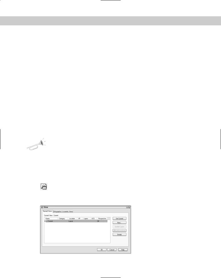
command. (You can also choose Named Views from the View toolbar.) The View dialog box opens with the Named Views tab active, as shown in Figure 8-9.
Figure 8-9: The View dialog box.
Chapter 8 Viewing Your Drawing 133
The View dialog box has the following columns:
Name: Displays the name of saved named views. You can click the name of a selected view to change its name.
Category: You can assign categories for views for the purpose of organizing sheets in the Sheet Set Manager. Typical categories might be elevation and plan or top and section. (AutoCAD only.) For more information, see Chapter 26.
Location: You can place views on the Model tab, where you usually draw, or on a layout tab. I explain layouts in Chapter 17.
VP: You can associate a view with a floating viewport on a sheet in a sheet set. (AutoCAD only.) I explain floating viewports briefly in this chapter and cover them thoroughly in Chapter 17. Sheet sets are covered in Chapter 26.
Layers: You can save layer visibility settings with the named view so that every time you display the view, you see the same layer settings. I explain layers in Chapter 11.
UCS: You can save a UCS (User Coordinate System) with the view, so that each view can have its own UCS. I explain UCSs later in this chapter.
Perspective: This column states whether the named view is a perspective view. You can create a perspective view using the DVIEW command in both AutoCAD and AutoCAD LT, covered in this chapter. In AutoCAD only, you can also use the 3DORBIT command (see Chapter 22).
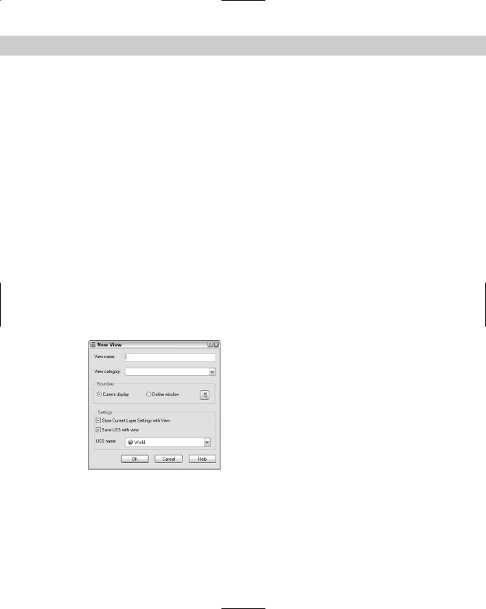
When you first open this dialog box, it shows only one view, called Current, which is the current display. Click New to open the New View dialog box, shown in Figure 8-10. Type a name for your view in the View Name text box.
Figure 8-10: The New View dialog box.
View names can be up to 255 characters and can include spaces. As I explained in the previous discussion of the View dialog box, you can save a User Coordinate System, a category, and layer visibility settings with a view. Select the Current Display option button to use the current display as the view. Otherwise, choose Select Window, click the Define View Window button, and specify a window around the view that you want.
Choose OK to return to the View dialog box, where you see your new view listed. Click OK to return to your drawing.

134 Part II Drawing in Two Dimensions
Tip |
In a very large drawing, you can create views as soon as you create the title block — for exam- |
|
ple, one for each quadrant of the drawing, and another for the title block lettering. This helps |
|
you move quickly from one section of the drawing to another. As you determine the need for |
|
more specific views, you can add them. |
You can use the New View dialog box to define several views at once. Here’s how:
1.Choose View Named Views.
2.Click New.
3.Type the name of the first view in the View Name text box.
4.Choose the Define Window radio button.
5.Click the Define View Window button to return to your drawing.
6.If necessary, adjust the display by zooming and panning. The display change is done transparently.
7.At the Specify first corner: prompt, pick one corner of a rectangular window.
8.At the Specify opposite corner: prompt, pick the diagonally opposite corner of the window to return to the New View dialog box.
9.Click OK to return to the View dialog box.
10.Repeat Steps 2 through 8 for all additional views.
Displaying a view
The View dialog box enables you to easily display any view you have saved. Follow these steps:
1.Choose View Named Views.
2.Choose the view you want to restore.
3.Click Set Current.
4.Click OK.
For quick access to named views, open the View toolbar and choose a named view from the drop-down list.
Using other View control functions
You can use the View dialog box to manage named views. Choose View Named Views to open the View dialog box. You can also find these features by right-clicking inside the View dialog box.
To delete a view, choose the view you want to delete and press the Delete key on your keyboard.
To rename a view, click it once and then a second time, but without double-clicking. Type a new name and press Enter.

Chapter 8 Viewing Your Drawing 135
On the
CD-ROM
To change the layer states that you saved with the view, change the states of any layers before opening the dialog box. Then open the View dialog box, choose a named view, and click Update Layers. The view now uses the current layer states.
To edit the boundaries of a view, choose the Edit Boundaries button. You are now back in your drawing and the current view boundaries are shown in black or white (depending on the color of your background). At the prompts, specify the two opposite corners that you want to bound the view and press Enter.
To see a description of a view, choose the view for which you want to see a description and click Details. The View Details dialog box opens, which provides some statistics about the view.
The drawing used in the following Step-by-Step exercise on working with views, ab08-b.dwg, is in the Drawings folder on the CD-ROM.
STEP-BY-STEP: Working with Views
1.Open ab08-b.dwg from the CD-ROM if it is not already open from the previous exercise.
2.Save the file as ab08-01.dwg in your AutoCAD Bible folder.
3.Choose View Named Views to open the View dialog box.
4.Click New to open the New View dialog box.
5.In the View Name text box, type top left.
6.In the Category text box, type quarter-sections if you are using AutoCAD. If you use the Sheet Set Manager to define sheets (as explained in Chapter 26), this category could be used for a series of layout sheets that display quarters of the building.
7.Click the Define Window option button or the Define View Window button. This action returns you to your drawing temporarily.
8.At the Specify first corner: prompt, pick the top-left corner of your screen. At the Specify opposite corner: prompt, pick somewhere around the center of the warehouse. You are now back in the New View dialog box.
9.Click OK once.
10.Click New. Type bottom left in the text box of the New View dialog box.
11.Select Define Window and then click the Define View Window button. At the Specify first corner: prompt, pick the bottom-left corner of your screen. At the Specify Opposite corner: prompt, pick again around the center of the warehouse. Back in the New View dialog box, click OK. The View dialog box should list both of your views. Click OK to close the View dialog box.
12.Choose View Named Views. Choose bottom left from the View dialog box. Click Set Current and then click OK. AutoCAD or AutoCAD LT displays the view.
13.Save your drawing. The views you created are now part of the drawing database.
136 Part II Drawing in Two Dimensions
Using named views to manage a drawing
Using named views provides three additional advantages:
You can use named views when you open a drawing so that one of its views is immediately displayed.
You can open only the part of a drawing contained in a view.
You can turn a named view into a floating viewport for plotting purposes. (AutoCAD only.)
A drawing with a view
After you’ve saved views, you can use them to open a drawing so that a view is immediately displayed. Click Open on the Standard toolbar. In the Select File dialog box, choose the file that you want to open and check the Select Initial View check box. Then click Open. In the Select Initial View dialog box, choose the view that you want to display and click OK.
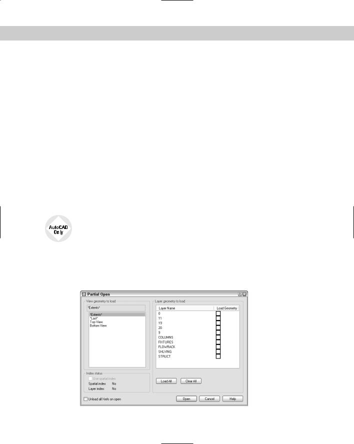
Partially opening a drawing
You may have a very large drawing that is slow and cumbersome to work with when it is completely opened. For example, if you have a surveyor’s drawing of an entire county, but you need to work only with one plat, you might want to open a named view containing only that plat.
You can open only the part of a drawing contained in a named view.
To partially open a drawing from within AutoCAD, follow these steps:
1.Choose File Open to open the Select File dialog box.
2.Choose a drawing and then click the Open button’s drop-down box. Choose Partial Open to open the Partial Open dialog box, shown in Figure 8-11.
Figure 8-11: Use the Partial Open dialog box to open only the part of a drawing contained in a named view.