

- •Foreword
- •Preface
- •Is This Book for You?
- •How This Book Is Organized
- •How to Use This Book
- •Doing the Exercises
- •Conventions Used in This Book
- •What the Icons Mean
- •About the CD-ROM
- •Other Information
- •Contacting the Author
- •Acknowledgments
- •Contents at a Glance
- •Contents
- •Getting Acquainted with AutoCAD and AutoCAD LT
- •Starting AutoCAD and AutoCAD LT
- •Creating a New Drawing
- •Using the AutoCAD and AutoCAD LT Interface
- •Creating Your First Drawing
- •Saving a Drawing
- •Summary
- •Creating a New Drawing from a Template
- •Working with Templates
- •Opening a Drawing with Default Settings
- •Opening an Existing Drawing
- •Using an Existing Drawing as a Prototype
- •Saving a Drawing Under a New Name
- •Summary
- •The Command Line
- •Command Techniques
- •Of Mice and Pucks
- •Getting Help
- •Summary
- •Typing Coordinates
- •Displaying Coordinates
- •Picking Coordinates on the Screen
- •Locating Points
- •Summary
- •Unit Types
- •Drawing Limits
- •Understanding Scales
- •Inserting a Title Block
- •Common Setup Options
- •The MVSETUP Command
- •Summary
- •Using the LINE Command
- •Drawing Rectangles
- •Drawing Polygons
- •Creating Construction Lines
- •Creating Rays
- •Summary
- •Drawing Circles
- •Drawing Arcs
- •Creating Ellipses and Elliptical Arcs
- •Making Donuts
- •Placing Points
- •Summary
- •Panning
- •The ZOOM Command
- •Aerial View
- •Named Views
- •Tiled Viewports
- •Snap Rotation
- •User Coordinate Systems
- •Isometric Drawing
- •Summary
- •Editing a Drawing
- •Selecting Objects
- •Summary
- •Copying and Moving Objects
- •Using Construction Commands
- •Creating a Revision Cloud
- •Hiding Objects with a Wipeout
- •Double-Clicking to Edit Objects
- •Grips
- •Editing with the Properties Palette
- •Selection Filters
- •Groups
- •Summary
- •Working with Layers
- •Changing Object Color, Linetype, and Lineweight
- •Working with Linetype Scales
- •Importing Layers and Linetypes from Other Drawings
- •Matching Properties
- •Summary
- •Drawing-Level Information
- •Object-Level Information
- •Measurement Commands
- •AutoCAD’s Calculator
- •Summary
- •Creating Single-Line Text
- •Understanding Text Styles
- •Creating Multiline Text
- •Creating Tables
- •Inserting Fields
- •Managing Text
- •Finding Text in Your Drawing
- •Checking Your Spelling
- •Summary
- •Working with Dimensions
- •Drawing Linear Dimensions
- •Drawing Aligned Dimensions
- •Creating Baseline and Continued Dimensions
- •Dimensioning Arcs and Circles
- •Dimensioning Angles
- •Creating Ordinate Dimensions
- •Drawing Leaders
- •Using Quick Dimension
- •Editing Dimensions
- •Summary
- •Understanding Dimension Styles
- •Defining a New Dimension Style
- •Changing Dimension Styles
- •Creating Geometric Tolerances
- •Summary
- •Creating and Editing Polylines
- •Drawing and Editing Splines
- •Creating Regions
- •Creating Boundaries
- •Creating Hatches
- •Creating and Editing Multilines
- •Creating Dlines
- •Using the SKETCH Command
- •Digitizing Drawings with the TABLET Command
- •Summary
- •Preparing a Drawing for Plotting or Printing
- •Creating a Layout in Paper Space
- •Working with Plot Styles
- •Plotting a Drawing
- •Summary
- •Combining Objects into Blocks
- •Inserting Blocks and Files into Drawings
- •Managing Blocks
- •Using Windows Features
- •Working with Attributes
- •Summary
- •Understanding External References
- •Editing an Xref within Your Drawing
- •Controlling Xref Display
- •Managing Xrefs
- •Summary
- •Preparing for Database Connectivity
- •Connecting to Your Database
- •Linking Data to Drawing Objects
- •Creating Labels
- •Querying with the Query Editor
- •Working with Query Files
- •Summary
- •Working with 3D Coordinates
- •Using Elevation and Thickness
- •Working with the User Coordinate System
- •Summary
- •Working with the Standard Viewpoints
- •Using DDVPOINT
- •Working with the Tripod and Compass
- •Getting a Quick Plan View
- •Shading Your Drawing
- •Using 3D Orbit
- •Using Tiled Viewports
- •Defining a Perspective View
- •Laying Out 3D Drawings
- •Summary
- •Drawing Surfaces with 3DFACE
- •Drawing Surfaces with PFACE
- •Creating Polygon Meshes with 3DMESH
- •Drawing Standard 3D Shapes
- •Drawing a Revolved Surface
- •Drawing an Extruded Surface
- •Drawing Ruled Surfaces
- •Drawing Edge Surfaces
- •Summary
- •Drawing Standard Shapes
- •Creating Extruded Solids
- •Drawing Revolved Solids
- •Creating Complex Solids
- •Sectioning and Slicing Solids
- •Using Editing Commands in 3D
- •Editing Solids
- •Listing Solid Properties
- •Summary
- •Understanding Rendering
- •Creating Lights
- •Creating Scenes
- •Working with Materials
- •Using Backgrounds
- •Doing the Final Render
- •Summary
- •Accessing Drawing Components with the DesignCenter
- •Accessing Drawing Content with Tool Palettes
- •Setting Standards for Drawings
- •Organizing Your Drawings
- •Working with Sheet Sets
- •Maintaining Security
- •Keeping Track of Referenced Files
- •Handling Errors and Crashes
- •Managing Drawings from Prior Releases
- •Summary
- •Importing and Exporting Other File Formats
- •Working with Raster Images
- •Pasting, Linking, and Embedding Objects
- •Summary
- •Sending Drawings
- •Opening Drawings from the Web
- •Creating Object Hyperlinks
- •Publishing Drawings
- •Summary
- •Working with Customizable Files
- •Creating Keyboard Shortcuts for Commands
- •Customizing Toolbars
- •Customizing Tool Palettes
- •Summary
- •Creating Macros with Script Files
- •Creating Slide Shows
- •Creating Slide Libraries
- •Summary
- •Creating Linetypes
- •Creating Hatch Patterns
- •Summary
- •Creating Shapes
- •Creating Fonts
- •Summary
- •Working with Menu Files
- •Customizing a Menu
- •Summary
- •Introducing Visual LISP
- •Getting Help in Visual LISP
- •Working with AutoLISP Expressions
- •Using AutoLISP on the Command Line
- •Creating AutoLISP Files
- •Summary
- •Creating Variables
- •Working with AutoCAD Commands
- •Working with Lists
- •Setting Conditions
- •Managing Drawing Objects
- •Getting Input from the User
- •Putting on the Finishing Touches
- •Summary
- •Understanding Local and Global Variables
- •Working with Visual LISP ActiveX Functions
- •Debugging Code
- •Summary
- •Starting to Work with VBA
- •Writing VBA Code
- •Getting User Input
- •Creating Dialog Boxes
- •Modifying Objects
- •Debugging and Trapping Errors
- •Moving to Advanced Programming
- •A Final Word
- •Installing AutoCAD and AutoCAD LT
- •Configuring AutoCAD
- •Starting AutoCAD Your Way
- •Configuring a Plotter
- •System Requirements
- •Using the CD with Microsoft Windows
- •What’s on the CD
- •Troubleshooting
- •Index

Chapter 18 Working with Blocks and Attributes |
531 |
3.Choose the Space Delimited File (SDF) option.
4.Choose Select Objects. Pick the eight armchairs in the lobby and the two offices. Press Enter to end selection.
5.Choose Template File. In the Template File dialog box, navigate to and choose ab18-i. txt from the CD-ROM. Click Open.
6.Choose Output File. In the Output File dialog box, choose your AutoCAD Bible folder and name the file ab18-02.txt. Click Save.
7. Click OK. The command line displays the message 8 records in extract file.
8.To view the output file, from the Windows task bar choose Start Run. Type Notepad and click Run. In Notepad, choose File Open and locate the ab18-02.txt file in your AutoCAD Bible folder. Click Open.
This exercise shows how to extract attributes using space delimited format. This format is easier to import into AutoCAD by copying and pasting. However, comma delimited format is easier to import into most spreadsheet programs.
Summary
In this chapter, I covered all the ways you can use blocks and attributes in your drawings. You read about:
Combining objects into blocks in your drawings so that you can edit them as a unit
Inserting blocks at any scale and rotation
Saving a block as a file
Copying objects by using the Windows Clipboard and drag-and-drop
Using the DesignCenter to import blocks from other drawings
Using attributes to place text and to create simple databases
Defining attributes
Inserting blocks with attributes and assigning values to the attributes
Extracting attribute data in both AutoCAD and AutoCAD LT
In the next chapter, I explain how to insert references (xrefs) to other files in your drawings.
|
|
|


Referencing
Other Drawings
Sometimes you need to refer to another drawing without inserting it. You may want to use part of another drawing as an example
for your current drawing or to see how the model in your drawing fits in with models in other drawings. Using an external reference is like laying one drawing on top of another and being able to see both at the same time.
Understanding External References
External references (commonly called xrefs) enable you to view
any drawing as a reference while in your current drawing. The external drawing is not part of your current drawing. The current drawing keeps track of the location and name of an external reference so you can always reference it easily. As with blocks, you can snap to objects in the external reference, thereby using it as a reference for the drawing process. You can also change the visibility settings of the xref’s layers.
Xrefs have several advantages over blocks:
Xrefs keep your drawing smaller than blocks. The externally referenced drawing doesn’t become part of your drawing. Your drawing maintains only a reference (name and location) to the other drawing.
You always have the most updated version of the xref. Each time you open a drawing, a current copy of the xref loads. By contrast, you would need to reinsert a file inserted as a block to see the most updated version.
In a team project, several people can use the same drawing as an xref, each having access to the latest changes.
Xrefs can be attached and detached easily for maximum flexibility or overlaid for temporary use. For example, you may not want the xref to be part of your drawing. If you’re using only the xref for reference, you may detach it before plotting.
19C H A P T E R
In This Chapter
Understanding external references
Attaching external references
Editing external references from within your drawing
Controlling the display of external references
Managing external references

534 Part III Working with Data
Attaching an external reference
The first step is to attach the external reference, which is just another drawing, to your current (host) drawing. When working with xrefs, you may find it useful to use the Reference toolbar. To open the Reference toolbar, right-click any toolbar and choose Reference.
To attach an xref, follow these steps:
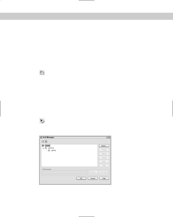
1.Choose External Reference from the Reference toolbar (or choose Insert Xref Manager) to start the XREF command. The Xref Manager (shown in Figure 19-1)
opens. It is your one-stop shopping mall for external references. This dialog box enables you to manage all your xrefs in one place.
If you don’t have any xrefs in use in a drawing, the External Reference dialog box is blank. If you do have xrefs in your drawing, this screen shows your current external references.
Figure 19-1: The Xref Manager.
2.To attach an external reference, choose Attach in the Xref Manager to open the Select Reference File dialog box. Choose the file you want to attach and click Open. The External Reference dialog box (shown in Figure 19-2) opens. The dialog box displays the file you chose along with its path (location).
3.Choose the type of xref in the Reference Type section:
•Attachment: Use an attachment when you want to be sure that the xref will be displayed if someone else xrefs your current drawing. In other words, that person will see your current drawing and your xref will be nested within it.
•Overlay: Use an overlay when you’re sharing drawings in a networked environment and don’t want to change your drawing by attaching an xref. If someone else attaches your drawing while you’re working on it, the overlay is not displayed.
New |
The new XREFTYPE system variable determines which of these two choices, Attachment or |
Feature |
Overlay, is automatically chosen in the Reference Type section. The default value, 0, uses the |
|
|
|
Attachment option. |

Chapter 19 Referencing Other Drawings 535
New
Feature
Figure 19-2: The External Reference dialog box.
4.From the Path Type drop-down list, choose the type of path you want to use:
•Full path: Specifies the full path of the xref drawing, including the drive letter (such as c:).
•Relative path: Specifies only part of the xref drawing’s path, assuming the current drive or folder. This option enables you to move an xref to a different drive that has the same folder structure.
•No path: Uses the current folder of the host drawing. This option enables you to move an xref to another folder with a different hierarchy.
5.Use the bottom half of the dialog box to specify the insertion point; X, Y, and Z scale factors; and rotation angle either in the dialog box or on-screen. These prompts are the same ones you use when inserting a block or file.
A new check box in the Scale section lets you specify the use of a uniform scale, so the Y and Z values are always the same as the X value.
6. Click OK to attach the xref.
If your current view does not show the entire xref, do a ZOOM Extents.
Cross- |
You can also attach an xref from a tool palette. For more information on tool palettes, see |
Reference |
Chapter 26. |
|
After you have the xref in your drawing, you can start to work. The xref is like a block, but you cannot explode it. However, you can use object snaps on all the objects in an xref, just as you can with blocks. This enables you to use the xref as a basis for your own drawing.
Opening an xref
Sometimes you need to open the xref to work on it directly. You may see an error that you want to correct, for example. The XOPEN command opens xrefs. The easiest way to use XOPEN is to click the xref to select it in your drawing, right-click, and choose Open Xref. The xref opens in its own window. If you look in the Xref Manager, the xref’s status is listed as Open.
536 Part III Working with Data
You can also select the file in the Xref Manager and click Open. When you click OK to close the Xref Manager, the xref drawing opens.
Viewing xref relationships
To see what type of xrefs you have in your drawing, choose External Reference from the Reference toolbar or Insert Xref Manager. The external references are listed in the Xref Manager. You can choose one of two views:
List view lists all the xrefs along with their status, size, type, date, and time saved, and the saved path, if any.
Tree view lists all the xrefs in a graphical view that shows their relationships. This view is great for understanding nested xrefs.
New |
When you insert a block that has an attached xref, the xref is maintained. In previous |
Feature |
releases, the xref was detached. |
|
Note You can change the width of the columns in List view by placing the cursor on a column dividing line until it changes to a two-headed arrow. Then drag in either direction.
Click any xref, and the Xref Found At box displays the location of the xref.
If the Xref Manager cannot find a drawing, it helps to know where it searches for xrefs. The Xref Manager searches for xrefs according to a specific order:
Path specified: To find the specified path xref.
Current folder: To find the current folder of the host drawing.
Project path: To check or change the project path, choose Tools Options and click the Files tab. Double-click Project Files Search Path. Click Add and then click Browse to navigate to a folder where you keep drawings that you may want to use as xrefs.
Support path: To check or change the project path, choose Tools Options and click the Files tab. Double-click Support File Search Path. Click Add and then click Browse to navigate to a folder.
Start-in folder: To find the start-in folder, right-click your AutoCAD 2005 or AutoCAD LT 2005 desktop shortcut and choose Properties.
On the |
The drawings used in the following Step-by-Step exercise on attaching xrefs, ab19-a.dwg |
CD-ROM |
and ab19-b.dwg, are in the Drawings folder on the CD-ROM. |
STEP-BY-STEP: Attaching Xrefs
1.Open ab19-a.dwg from the CD-ROM. This is the floor plan for a house. If the Reference toolbar is not displayed, right-click any toolbar and choose Reference.
2.Open Windows Explorer (right-click Start on the task bar and choose Explore). Copy ab19-b.dwg from the CD-ROM to your AutoCAD Bible folder.
Chapter 19 Referencing Other Drawings 537
3.In your drawing, choose External Reference Attach from the Reference toolbar. In the Select Reference File dialog box, choose ab19-b.dwg. Choose Open.
4.In the External Reference dialog box, you see the filename displayed. Make sure all Specify On-Screen check boxes are unchecked and click OK. You see ab19-b.dwg, which is a title block, in ab19-a.dwg.
5.Save the drawing as ab19-01.dwg in your AutoCAD Bible folder. Click the drawing’s Close box to close the drawing.
6.Start a new drawing using the acad.dwt template. Choose Format Units and choose Architectural. In the Units to Scale Drag-and-Drop Content drop-down list, choose Inches. Choose OK. Save it as ab19-02.dwg in your AutoCAD Bible folder.
7.Choose External Reference Attach from the Reference toolbar. In the Select
Reference File dialog box, choose ab19-01.dwg, which you just saved in your AutoCAD Bible folder. Choose Open.
8.In the External Reference dialog box, you see the filename displayed. Leave the defaults and click OK. Choose Zoom Extents from the Zoom flyout on the Standard toolbar. You see ab19-01.dwg, which includes both the title block and the floor plan of the house in your new drawing. The title block drawing (ab19-b.dwg) is a nested xref in the floor plan (ab19-01.dwg) xref. You see the following message (press F2 to open the Text Window so you can see the message that scrolls by):
Attach Xref “ab19-01”: C:\AutoCAD Bible\ab19-01.dwg “ab19-01” loaded.
Attach Xref “ab19-b”: C:\AutoCAD Bible\ab19-b.dwg “ab19-b” loaded.
9.To help you visualize the relationships among the three drawings, choose External Reference from the Reference toolbar. The Xref Manager lists both drawings. Click
Tree View at the top of the dialog box. You now see the two xrefs listed in a tree structure, showing their relationship more clearly, as shown in Figure 19-3. Click Cancel.
Figure 19-3: Tree view shows nested xrefs clearly.