


Starting to Draw
Learning AutoCAD or AutoCAD LT is a bit like trying to decide which came first — the chicken or the egg. On one hand, you need to
know many basics before you can start drawing. On the other hand, understanding those basics can be very difficult if you haven’t had the experience of drawing something. In this chapter, you resolve this problem by creating a simple drawing in AutoCAD or AutoCAD LT. The next few chapters then fill you in on basic information you need to move on to more complex drawings. By experiencing the drawing process first, the initial learning curve will be easier and smoother.
Getting Acquainted with AutoCAD and AutoCAD LT
AutoCAD and its younger brother, AutoCAD LT, are both created by Autodesk. Together they are the most widely used technical drawing programs anywhere. AutoCAD alone has more than 3,000,000 registered users. According to Autodesk, CAD stands for computer-aided design, but can also stand for computer-aided drafting or drawing.
The first version of AutoCAD, running under DOS, came out in 1982. AutoCAD was the first significant CAD program to run on a desktop computer. At the time, most other technical drawing programs ran on high-end workstations or even mainframes. AutoCAD LT was introduced in 1993, as a less expensive alternative to AutoCAD, for people who didn’t need all of AutoCAD’s advanced features.
AutoCAD’s advantages
AutoCAD’s success has been attributed to its famous open architecture — the flexibility that the end user has to customize the program using source code files in plain text (ASCII) format — and programming languages (such as AutoLISP and Visual Basic for Applications).
As a result, AutoCAD is the most flexible drafting program available, applicable to all fields. AutoCAD’s support for languages other than English, including those using other alphabets, is unparalleled, making AutoCAD without serious competition abroad. As a result, AutoCAD is used in all disciplines and in more than 150 countries.
C 1H A P T E R
In This Chapter
Getting acquainted with AutoCAD and AutoCAD LT
Starting AutoCAD
and AutoCAD LT
Creating a new drawing
Using the AutoCAD and AutoCAD LT interface
Creating your first drawing
Saving your drawing
Closing a drawing and exiting AutoCAD and AutoCAD LT

4 |
Part I AutoCAD and AutoCAD LT Basics |
Through a high level of technical innovation and expertise, Autodesk has created a program with unequaled features and capabilities, including 3D surface and solid modeling and visualization, access to external databases, intelligent dimensioning, importing and exporting of other file formats, Internet support, and much more.
The major disciplines that use AutoCAD are
Architectural, Engineering, and Construction (AEC)
Mechanical
Geographic Information Systems (GIS)
Surveying and Civil Engineering
Facilities management
Electrical/electronic
Multimedia
However, AutoCAD has many other lesser-known uses, such as pattern making in the garment industry, sign making, and so on. In this book, I try to provide examples from many fields. The world of AutoCAD is very broad, and you can learn from seeing the many approaches that AutoCAD makes possible.
AutoCAD LT’s features
AutoCAD LT’s advantage is its lower cost and its compatibility with AutoCAD. The programming code that creates AutoCAD LT is a subset of the code used in AutoCAD. Here are the major differences between AutoCAD and AutoCAD LT:
AutoCAD includes features that enable CAD managers to hold drawings to certain standards, such as layer names and text styles. AutoCAD LT doesn’t contain these features.
AutoCAD LT is not customizable to the extent that AutoCAD is; AutoCAD is both programmable and fully customizable.
AutoCAD LT includes only minimal 3D options; AutoCAD includes a full-featured 3D capability.
AutoCAD LT has fewer presentation features than AutoCAD, which includes gradient fills, true color display, and 3D rendering.
AutoCAD LT is deployable on a network but does not include AutoCAD’s network license management feature that includes reporting and flexible licensing.
AutoCAD LT does not offer database connectivity; AutoCAD does.
AutoCAD LT does not include AutoCAD’s quick-dimensioning feature, which allows you to quickly insert a number of dimensions one after the other.
AutoCAD LT does not include two of AutoCAD 2005’s new features — sheet sets and fields.
AutoCAD and AutoCAD LT have a few other minor differences as well. Some of these differences are only in the user interface, so you can accomplish the same task but the procedure is slightly different.
Chapter 1 Starting to Draw |
5 |
Starting AutoCAD and AutoCAD LT
This section starts the quick tour of AutoCAD and AutoCAD LT. The first step is to start the program.
On the |
The CD-ROM contains a 30-day trial version of AutoCAD 2005. Look in \Software\AutoCAD |
CD-ROM |
2005. You can order AutoCAD LT 2005 at www.autodesk.com/30day. |
This book covers AutoCAD 2005 and AutoCAD LT 2005 running on Windows 2000 or Windows XP Home/Professional. Every computer is set up somewhat differently, so you may need to adjust the following steps slightly. If you didn’t install the software yourself and are unfamiliar with the folders (also called directories) on your computer, get help from someone who is familiar with your computer system.
Cross- |
If you need help installing AutoCAD or AutoCAD LT, see Appendix A. |
Reference |
|
By default, installing AutoCAD or AutoCAD LT places a shortcut on your desktop, as shown in Figure 1-1. You can double-click one of the shortcuts to launch the program that is installed on your machine, or you may choose one of the following:
For AutoCAD: Start (All) Programs Autodesk AutoCAD 2005 AutoCAD2005
For AutoCAD LT: Start (All) Programs Autodesk AutoCAD LT 2005 AutoCAD LT 2005
Figure 1-1: A shortcut on the desktop provides a quick way to open
AutoCAD or AutoCAD LT.
Creating a New Drawing
After you launch AutoCAD or AutoCAD LT, you are automatically in a new drawing named Drawing1.dwg. You can see the drawing name on the title bar. You can start drawing immediately. In Chapter 2, I explain how to start a drawing based on a template and how to open an existing drawing.
STEP-BY-STEP: Starting AutoCAD or AutoCAD LT
1.Click Start on the taskbar at the bottom of your screen.
2.Choose one of the following:
•For AutoCAD: (All) Programs Autodesk AutoCAD 2005 AutoCAD 2005
•For AutoCAD LT: (All) Programs Autodesk AutoCAD LT 2005 AutoCAD LT 2005 You see a blank drawing named Drawing1.dwg.

6 |
Part I AutoCAD and AutoCAD LT Basics |
If you are continuing with this chapter, keep this drawing open. I cover exiting from AutoCAD and AutoCAD LT later in this chapter.
Using the AutoCAD and AutoCAD LT Interface
You’re probably eager to start drawing. First, though, it helps to get the lay of the land.
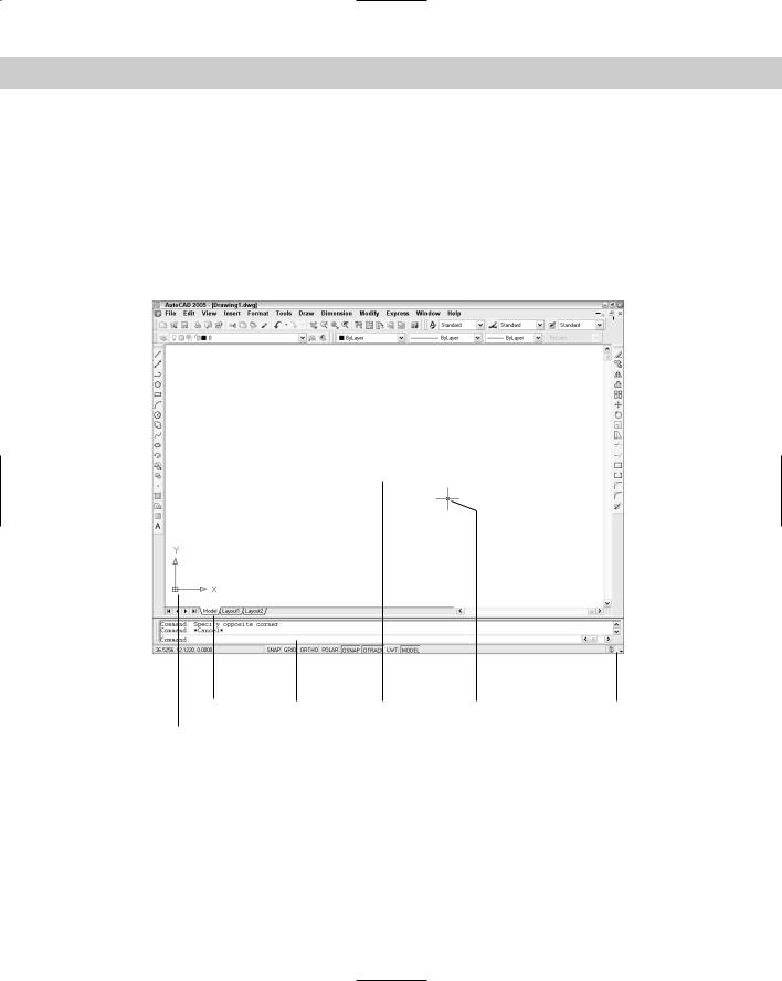
Figure 1-2 shows the screen that appears when you first open AutoCAD or AutoCAD LT. Your screen may look somewhat different — remember that AutoCAD and AutoCAD LT can be customized in many ways — but the general features will be the same.
Cross-
Reference
You may see the Tool Palettes window with some sample office furniture and hatches. You may also see (AutoCAD only) the Sheet Set Manager. I cover the Tools Palettes and Sheet Set Manager in Chapter 26. For now, you can click the palettes’ close button to get them out of the way. You may also see the Info Palette, which I cover in Chapter 3. Finally, your screen is probably black, rather than the white screen you see in Figure 1-2. I explain how to change the drawing area color in Appendix A. The AutoCAD LT screen is very similar to the AutoCAD screen.
The AutoCAD/AutoCAD LT screen consists of four important areas. These are discussed in the next sections.
The drawing area
The blank area in the middle of the screen, the graphics window or drawing area, is where you draw. You can think of this as a sheet of drafting paper, except that this piece of paper can be any size — even the size of a huge factory!
At the bottom of the drawing area is a tab labeled Model. You draw on this tab. You use the layout tabs to lay out your drawing for plotting. (See Chapter 17 for details.)
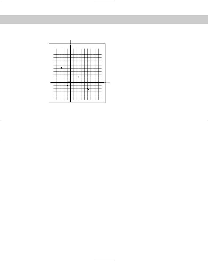
When you start to draw, you need to specify where to start drawing. One way is to use coordinates. To specify a coordinate, the universally accepted convention is to put the X coordinate first, followed by a comma, and then the Y coordinate. Figure 1-3 shows some coordinates on X and Y axes.
Cross- Chapter 4 is devoted to explaining how to specify coordinates. To create three-dimensional Reference models, you need to add a Z coordinate when specifying a point. Chapter 21 discusses three-
dimensional coordinates.
The UCS icon
Notice the symbol with two arrows at the bottom-left corner of the drawing area in Figure 1-2. This symbol is called the User Coordinate System (UCS) icon. The arrows point to the positive directions of the X and Y axes to help you keep your bearings.
Cross- |
You can change the look of this icon, as I explain in Chapter 8. |
Reference |
|
Chapter 1 Starting to Draw |
7 |
|
|
|
|
|
|
|
|
|
|
|
|
Drawing close button |
||||||||
|
|
|
|
|
|
|
|
|
Styles toolbar Application close button |
|||||||||||
|
|
|
|
|
|
|
|
|
|
|
|
Application maximize button |
|
|||||||
Draw toolbar |
|
|
|
Properties toolbar |
Application minimize button |
|
|
|
||||||||||||
|
|
Layers toolbar Standard toolbar |
|
|
|
Drawing minimize button |
|
|
|
|
|
|||||||||
|
|
Menu bar |
|
Title bar |
|
|
|
|
|
Drawing maximize button |
|
|
|
|
||||||
|
|
|
|
|
|
|
|
|
|
|
|
|
|
|
|
|
|
|
|
|
|
|
|
|
|
|
|
|
|
|
|
|
|
|
|
|
|
|
|
|
|
|
|
|
|
|
|
|
|
|
|
|
|
|
|
|
|
|
|
|
|
|
|
|
|
|
|
|
|
|
|
|
|
|
|
|
|
|
|
|
|
|
|
|
|
|
|
|
|
|
|
|
|
|
|
|
|
|
|
|
|
|
|
|
|
|
|
|
|
|
|
|
|
|
|
|
|
|
|
|
|
|
|
|
|
|
|
|
|
|
|
|
|
|
|
|
|
|
|
|
|
|
|
|
|
|
|
|
|
|
|
|
|
|
|
|
|
|
|
|
|
|
|
|
|
|
|
|
|
|
|
|
|
|
|
|
|
|
|
|
|
|
|
|
|
|
|
|
|
|
|
|
|
|
|
|
|
|
|
|
|
|
|
|
|
|
|
|
|
Layout tabs |
Status bar |
Crosshairs |
|
Modify toolbar |
Model tab Command line Drawing area |
Pickbox |
Status bar menu |
||
User Coordinate System (UCS) icon
Figure 1-2: The AutoCAD and AutoCAD LT screen are almost identical.
The crosshairs
In the drawing area of Figure 1-2, notice the two intersecting lines with a small box at their intersection. The small box is called the pickbox because it helps you to pick objects. The lines are called crosshairs. They show you the location of the mouse cursor in relation to other objects in your drawing.
8 |
Part I AutoCAD and AutoCAD LT Basics |
Y axis
-3,5 
 3,2
3,2
0,0 |
X axis |
|
-1,-1 
 6,-2
6,-2
Figure 1-3: Some X,Y coordinates.
As you move your mouse around, the pickbox and crosshairs move with your mouse. At the bottom of your screen, at the left end of the status bar (described later), you can see the X,Y coordinates changing as you move the mouse.
The menus and toolbars
At the top of your screen is the title bar, and directly beneath the title bar is a menu bar. Below that are two rows of toolbars. In addition, your screen has two more toolbars, the Draw and Modify toolbars, which are probably docked at the left and right sides of the screen (refer to Figure 1-2). Use the menus and toolbars together to give AutoCAD or AutoCAD LT commands to draw, edit, get information, and so on.
Because you can customize the menus and toolbars to suit your needs, your screen may appear somewhat different. AutoCAD and AutoCAD LT provide many more toolbars that you can display when you need them. Some examples of the toolbars are Dimension, View, and Zoom. You learn about these and more, later in this book.
The command line
At the bottom of the screen, you see a separate window showing approximately three lines of text. (You can change it to show as many lines as you like by dragging the top edge of the window up or down.) Notice the word Command:. This is the command line. All commands can be executed by typing them on the command line.
Even if you use a menu item or toolbar button to execute a command, you may need to look at the command line to see how AutoCAD or AutoCAD LT responds. Often, AutoCAD and AutoCAD LT provide options that must be typed in from the keyboard. Also, text that you type appears on the command line. For example, when you type coordinates specifying a point, they appear on the command line. To see more of the command line, press F2 to open the AutoCAD or