

- •Foreword
- •Preface
- •Is This Book for You?
- •How This Book Is Organized
- •How to Use This Book
- •Doing the Exercises
- •Conventions Used in This Book
- •What the Icons Mean
- •About the CD-ROM
- •Other Information
- •Contacting the Author
- •Acknowledgments
- •Contents at a Glance
- •Contents
- •Getting Acquainted with AutoCAD and AutoCAD LT
- •Starting AutoCAD and AutoCAD LT
- •Creating a New Drawing
- •Using the AutoCAD and AutoCAD LT Interface
- •Creating Your First Drawing
- •Saving a Drawing
- •Summary
- •Creating a New Drawing from a Template
- •Working with Templates
- •Opening a Drawing with Default Settings
- •Opening an Existing Drawing
- •Using an Existing Drawing as a Prototype
- •Saving a Drawing Under a New Name
- •Summary
- •The Command Line
- •Command Techniques
- •Of Mice and Pucks
- •Getting Help
- •Summary
- •Typing Coordinates
- •Displaying Coordinates
- •Picking Coordinates on the Screen
- •Locating Points
- •Summary
- •Unit Types
- •Drawing Limits
- •Understanding Scales
- •Inserting a Title Block
- •Common Setup Options
- •The MVSETUP Command
- •Summary
- •Using the LINE Command
- •Drawing Rectangles
- •Drawing Polygons
- •Creating Construction Lines
- •Creating Rays
- •Summary
- •Drawing Circles
- •Drawing Arcs
- •Creating Ellipses and Elliptical Arcs
- •Making Donuts
- •Placing Points
- •Summary
- •Panning
- •The ZOOM Command
- •Aerial View
- •Named Views
- •Tiled Viewports
- •Snap Rotation
- •User Coordinate Systems
- •Isometric Drawing
- •Summary
- •Editing a Drawing
- •Selecting Objects
- •Summary
- •Copying and Moving Objects
- •Using Construction Commands
- •Creating a Revision Cloud
- •Hiding Objects with a Wipeout
- •Double-Clicking to Edit Objects
- •Grips
- •Editing with the Properties Palette
- •Selection Filters
- •Groups
- •Summary
- •Working with Layers
- •Changing Object Color, Linetype, and Lineweight
- •Working with Linetype Scales
- •Importing Layers and Linetypes from Other Drawings
- •Matching Properties
- •Summary
- •Drawing-Level Information
- •Object-Level Information
- •Measurement Commands
- •AutoCAD’s Calculator
- •Summary
- •Creating Single-Line Text
- •Understanding Text Styles
- •Creating Multiline Text
- •Creating Tables
- •Inserting Fields
- •Managing Text
- •Finding Text in Your Drawing
- •Checking Your Spelling
- •Summary
- •Working with Dimensions
- •Drawing Linear Dimensions
- •Drawing Aligned Dimensions
- •Creating Baseline and Continued Dimensions
- •Dimensioning Arcs and Circles
- •Dimensioning Angles
- •Creating Ordinate Dimensions
- •Drawing Leaders
- •Using Quick Dimension
- •Editing Dimensions
- •Summary
- •Understanding Dimension Styles
- •Defining a New Dimension Style
- •Changing Dimension Styles
- •Creating Geometric Tolerances
- •Summary
- •Creating and Editing Polylines
- •Drawing and Editing Splines
- •Creating Regions
- •Creating Boundaries
- •Creating Hatches
- •Creating and Editing Multilines
- •Creating Dlines
- •Using the SKETCH Command
- •Digitizing Drawings with the TABLET Command
- •Summary
- •Preparing a Drawing for Plotting or Printing
- •Creating a Layout in Paper Space
- •Working with Plot Styles
- •Plotting a Drawing
- •Summary
- •Combining Objects into Blocks
- •Inserting Blocks and Files into Drawings
- •Managing Blocks
- •Using Windows Features
- •Working with Attributes
- •Summary
- •Understanding External References
- •Editing an Xref within Your Drawing
- •Controlling Xref Display
- •Managing Xrefs
- •Summary
- •Preparing for Database Connectivity
- •Connecting to Your Database
- •Linking Data to Drawing Objects
- •Creating Labels
- •Querying with the Query Editor
- •Working with Query Files
- •Summary
- •Working with 3D Coordinates
- •Using Elevation and Thickness
- •Working with the User Coordinate System
- •Summary
- •Working with the Standard Viewpoints
- •Using DDVPOINT
- •Working with the Tripod and Compass
- •Getting a Quick Plan View
- •Shading Your Drawing
- •Using 3D Orbit
- •Using Tiled Viewports
- •Defining a Perspective View
- •Laying Out 3D Drawings
- •Summary
- •Drawing Surfaces with 3DFACE
- •Drawing Surfaces with PFACE
- •Creating Polygon Meshes with 3DMESH
- •Drawing Standard 3D Shapes
- •Drawing a Revolved Surface
- •Drawing an Extruded Surface
- •Drawing Ruled Surfaces
- •Drawing Edge Surfaces
- •Summary
- •Drawing Standard Shapes
- •Creating Extruded Solids
- •Drawing Revolved Solids
- •Creating Complex Solids
- •Sectioning and Slicing Solids
- •Using Editing Commands in 3D
- •Editing Solids
- •Listing Solid Properties
- •Summary
- •Understanding Rendering
- •Creating Lights
- •Creating Scenes
- •Working with Materials
- •Using Backgrounds
- •Doing the Final Render
- •Summary
- •Accessing Drawing Components with the DesignCenter
- •Accessing Drawing Content with Tool Palettes
- •Setting Standards for Drawings
- •Organizing Your Drawings
- •Working with Sheet Sets
- •Maintaining Security
- •Keeping Track of Referenced Files
- •Handling Errors and Crashes
- •Managing Drawings from Prior Releases
- •Summary
- •Importing and Exporting Other File Formats
- •Working with Raster Images
- •Pasting, Linking, and Embedding Objects
- •Summary
- •Sending Drawings
- •Opening Drawings from the Web
- •Creating Object Hyperlinks
- •Publishing Drawings
- •Summary
- •Working with Customizable Files
- •Creating Keyboard Shortcuts for Commands
- •Customizing Toolbars
- •Customizing Tool Palettes
- •Summary
- •Creating Macros with Script Files
- •Creating Slide Shows
- •Creating Slide Libraries
- •Summary
- •Creating Linetypes
- •Creating Hatch Patterns
- •Summary
- •Creating Shapes
- •Creating Fonts
- •Summary
- •Working with Menu Files
- •Customizing a Menu
- •Summary
- •Introducing Visual LISP
- •Getting Help in Visual LISP
- •Working with AutoLISP Expressions
- •Using AutoLISP on the Command Line
- •Creating AutoLISP Files
- •Summary
- •Creating Variables
- •Working with AutoCAD Commands
- •Working with Lists
- •Setting Conditions
- •Managing Drawing Objects
- •Getting Input from the User
- •Putting on the Finishing Touches
- •Summary
- •Understanding Local and Global Variables
- •Working with Visual LISP ActiveX Functions
- •Debugging Code
- •Summary
- •Starting to Work with VBA
- •Writing VBA Code
- •Getting User Input
- •Creating Dialog Boxes
- •Modifying Objects
- •Debugging and Trapping Errors
- •Moving to Advanced Programming
- •A Final Word
- •Installing AutoCAD and AutoCAD LT
- •Configuring AutoCAD
- •Starting AutoCAD Your Way
- •Configuring a Plotter
- •System Requirements
- •Using the CD with Microsoft Windows
- •What’s on the CD
- •Troubleshooting
- •Index
538 Part III Working with Data
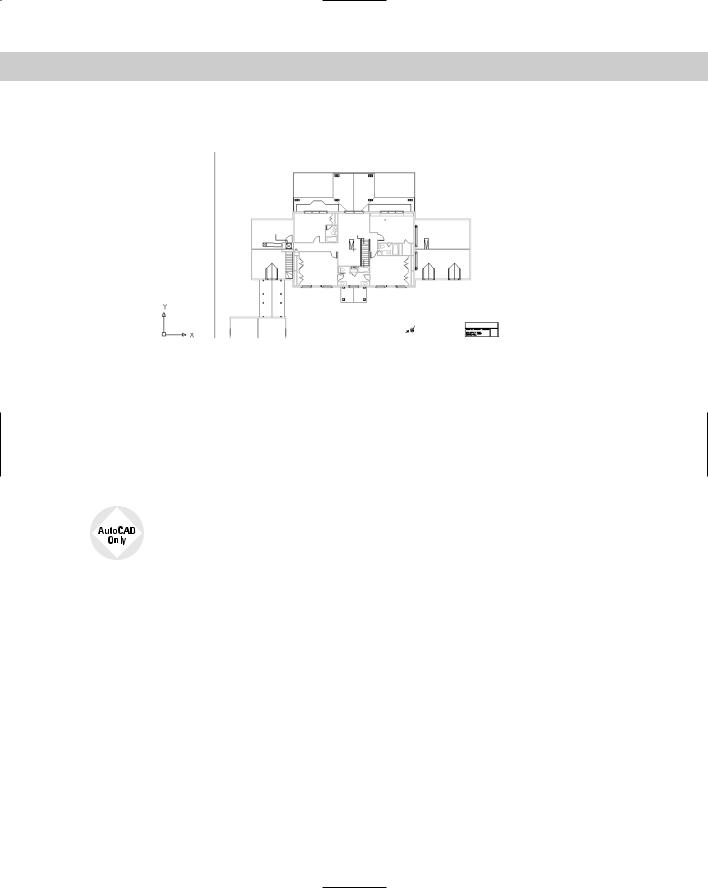
10. Save your drawing. It should look like Figure 19-4.
Figure 19-4: The current drawing is blank but displays an xref of a house plan that has a nested xref of a title block.
Editing an Xref within Your Drawing
While you’re working in a drawing with an external reference, you may decide that the external reference needs some modification. The same may apply if you inserted a file as a block. You can make changes to the xref or block and save those changes back to the original drawing. You can even transfer objects from your drawing to the xref or block, and vice versa. This feature is called in-place editing.
AutoCAD LT doesn’t include the in-place editing feature. Instead, you need to explode the block and redefine it (for blocks) or open the original file and modify it (for xrefs).
The steps to edit an xref or block are as follows:
1.Choose the xref or block in your drawing.
2.Choose from any nested xrefs.
3.Select the objects you want to edit to add them to the working set of objects being edited.
4.Edit the objects.
5.If desired, add or remove objects from the working set to transfer them to or from the xref or block.
6.Save the changes back to the xref or block.
Choosing the xref or block to edit
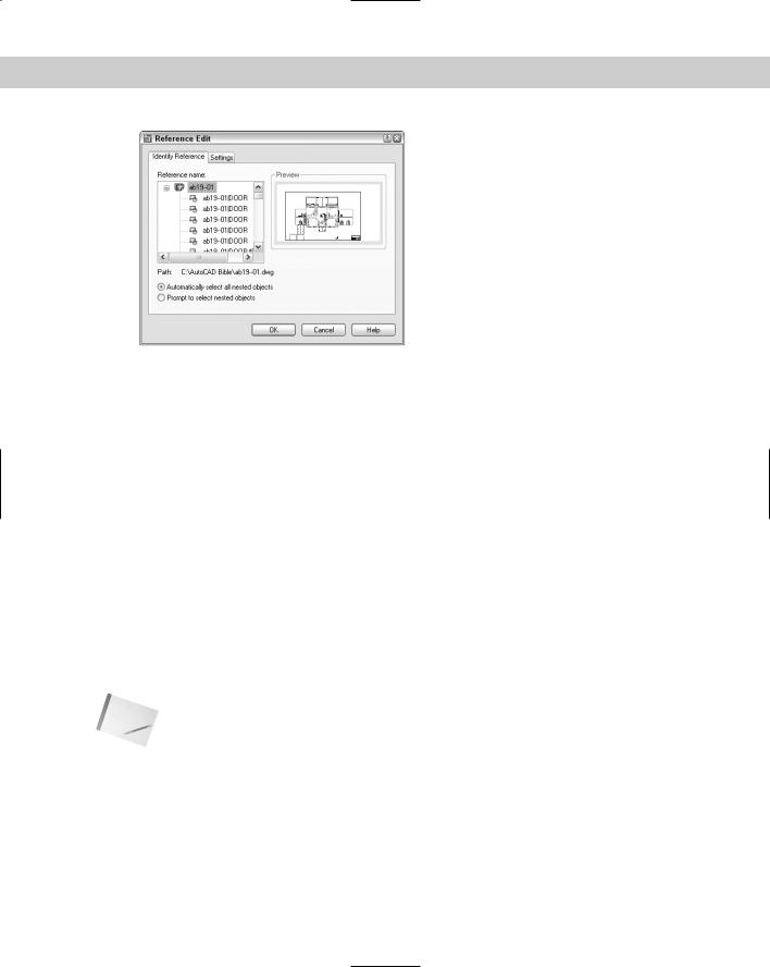
To start the process of in-place editing, double-click the xref you want to edit. The Reference Edit dialog box opens, shown in Figure 19-5. You can also choose Modify Xref and Block Editing Edit Reference In-Place and then select the xref you want to edit.
Chapter 19 Referencing Other Drawings 539
Figure 19-5: The Reference Edit dialog box enables you to choose which reference you want to edit, including nested references.
As you click each of the available references, its preview appears at the right. If the xref has nested objects, choose one of the following options (if not, ignore this section of the dialog box):
Automatically select all nested objects: Includes all nested objects in the editing
Prompt to select nested objects: Prompts you to select the nested objects you want to edit
For more control, click the Settings tab to set the following options:
Create unique layer, style, and block names: Displays layer, style, and block names with a prefix of $#$, to help distinguish them from these named items in your main drawing
Display attribute definitions for editing: Enables you to edit attribute definitions of blocks with attributes (See Chapter 18 for details on attributes)
Lock objects not in working set: Locks objects in the host drawing so that you can’t accidentally modify them
Click OK to close the Reference Edit dialog box.
Note If the references come from an earlier release, you see a warning that if you save your changes back to the xref, that xref will be updated to an AutoCAD 2005 or AutoCAD LT 2005 drawing.
If you checked the Prompt to Select Nested Objects option, you get a prompt to select nested objects. Complete object selection to define the working set — the objects you can edit. Other objects are faded by 50 percent (the default, determined by the XFADECTL system variable).
The Refedit toolbar opens, shown in Figure 19-6, and you see the message Use REFCLOSE or the Refedit toolbar to end reference editing session on the command line. You’re now ready to edit the xref or block.
540 Part III Working with Data
Figure 19-6: The Refedit toolbar.
Editing the xref
There are several types of edits you can make on the working set of objects from the xref or block:
If you change an object’s properties, such as its layer, the object will have the new object property.
If you erase an object, the object is deleted from the xref or block.
If you draw a new object, the object is added to the xref or block. An exception is if you create a new object by editing objects outside the working set. For example, if you break a line (not in the working set) into two lines, nothing is added to the working set.
You can transfer an object from the main drawing to the xref or block. Select an object and choose Add Objects to Working Set. Remember that the working set consists of objects from the xref or block, so if you add objects to the working set, they become part of the xref or block.
You can transfer an object from the xref or block to the main drawing. Select an object and choose Remove Objects from Working Set. The working set consists of objects from the xref or block, so if you remove objects from the working set, they’re no longer part of the xref or block; instead, they become part of your main drawing.
After you finish editing the working set, if you like what you did, choose Save Back Changes to Reference from the Refedit toolbar. Otherwise, choose Discard Changes to Reference.
When you save changes to a block, block definitions are redefined and all instances of the block are regenerated according to the new definition. If you gave an xref object properties that don’t exist in the xref, such as a layer, the new property is copied to the xref so that the object can keep that property.
On the |
The drawings used in the following Step-by-Step exercise on editing an xref in place, |
CD-ROM |
ab19-a.dwg and ab19-b.dwg, are in the Drawings folder on the CD-ROM. |
STEP-BY-STEP: Editing an Xref in Place
1.Open ab19-a.dwg from the CD-ROM. Save it as ab19-03.dwg in your AutoCAD Bible folder.
2.Open ab19-b.dwg from the CD-ROM. Save it as ab19-04.dwg in your AutoCAD Bible folder. Click the Close box of ab19-04.dwg to close the drawing (but not the program), leaving ab19-03.dwg on your screen.
3.Choose Insert External Reference and choose ab19-04.dwg from the AutoCAD Bible folder. Click Open. From the External Reference dialog box, uncheck all the Specify OnScreen check boxes and click OK to insert the xref.
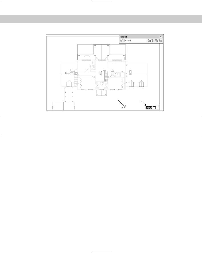
4.Double-click the title block. The Reference Edit dialog box opens. Choose ab19-04.dwg. It is displayed in the preview box. Click OK. The Refedit toolbar opens. You can now edit the xref. Your screen should look like Figure 19-7.
Chapter 19 Referencing Other Drawings 541
2 1
Figure 19-7: The title block is an xref in the drawing of the floor plan.
5.Select the title block again and choose Explode.
6.Choose Draw Text Single Line Text. At the Specify start point of text or
[Justify/Style]: prompt, pick 1 in Figure 19-7. At the Specify height <0'-0 3/16">: prompt, type 10 . Press Enter again for the rotation angle.
7.Type Davis Floor Plan and press Enter twice to end the command.
8.Choose the text (the name and address of the architect) at the bottom of the title block and change its color to red to make it stand out.
9.Select the letter N and arrow symbol at 2 in Figure 19-7. To transfer these objects from the xref to the floor plan drawing, choose Remove Objects from Working Set from the Refedit toolbar.
10.To save the changes, choose Save Back Changes to Reference. Click OK again at the dialog box that informs you that all reference edits will be saved. You see the following information on the command line:
The following symbols will be permanently bound to the current drawing:
Layers: $0$TITLEBLK
Text Styles: $0$ROMANS, $0$ROMAND Blocks: $0$KNTITL
Enter option [Save/Discard reference changes] <Save>: _sav Regenerating model.
11 objects added to ab19-04
1 object removed from ab19-04
1 xref instance updated
ab19-04 redefined and reloaded.