

- •Foreword
- •Preface
- •Is This Book for You?
- •How This Book Is Organized
- •How to Use This Book
- •Doing the Exercises
- •Conventions Used in This Book
- •What the Icons Mean
- •About the CD-ROM
- •Other Information
- •Contacting the Author
- •Acknowledgments
- •Contents at a Glance
- •Contents
- •Getting Acquainted with AutoCAD and AutoCAD LT
- •Starting AutoCAD and AutoCAD LT
- •Creating a New Drawing
- •Using the AutoCAD and AutoCAD LT Interface
- •Creating Your First Drawing
- •Saving a Drawing
- •Summary
- •Creating a New Drawing from a Template
- •Working with Templates
- •Opening a Drawing with Default Settings
- •Opening an Existing Drawing
- •Using an Existing Drawing as a Prototype
- •Saving a Drawing Under a New Name
- •Summary
- •The Command Line
- •Command Techniques
- •Of Mice and Pucks
- •Getting Help
- •Summary
- •Typing Coordinates
- •Displaying Coordinates
- •Picking Coordinates on the Screen
- •Locating Points
- •Summary
- •Unit Types
- •Drawing Limits
- •Understanding Scales
- •Inserting a Title Block
- •Common Setup Options
- •The MVSETUP Command
- •Summary
- •Using the LINE Command
- •Drawing Rectangles
- •Drawing Polygons
- •Creating Construction Lines
- •Creating Rays
- •Summary
- •Drawing Circles
- •Drawing Arcs
- •Creating Ellipses and Elliptical Arcs
- •Making Donuts
- •Placing Points
- •Summary
- •Panning
- •The ZOOM Command
- •Aerial View
- •Named Views
- •Tiled Viewports
- •Snap Rotation
- •User Coordinate Systems
- •Isometric Drawing
- •Summary
- •Editing a Drawing
- •Selecting Objects
- •Summary
- •Copying and Moving Objects
- •Using Construction Commands
- •Creating a Revision Cloud
- •Hiding Objects with a Wipeout
- •Double-Clicking to Edit Objects
- •Grips
- •Editing with the Properties Palette
- •Selection Filters
- •Groups
- •Summary
- •Working with Layers
- •Changing Object Color, Linetype, and Lineweight
- •Working with Linetype Scales
- •Importing Layers and Linetypes from Other Drawings
- •Matching Properties
- •Summary
- •Drawing-Level Information
- •Object-Level Information
- •Measurement Commands
- •AutoCAD’s Calculator
- •Summary
- •Creating Single-Line Text
- •Understanding Text Styles
- •Creating Multiline Text
- •Creating Tables
- •Inserting Fields
- •Managing Text
- •Finding Text in Your Drawing
- •Checking Your Spelling
- •Summary
- •Working with Dimensions
- •Drawing Linear Dimensions
- •Drawing Aligned Dimensions
- •Creating Baseline and Continued Dimensions
- •Dimensioning Arcs and Circles
- •Dimensioning Angles
- •Creating Ordinate Dimensions
- •Drawing Leaders
- •Using Quick Dimension
- •Editing Dimensions
- •Summary
- •Understanding Dimension Styles
- •Defining a New Dimension Style
- •Changing Dimension Styles
- •Creating Geometric Tolerances
- •Summary
- •Creating and Editing Polylines
- •Drawing and Editing Splines
- •Creating Regions
- •Creating Boundaries
- •Creating Hatches
- •Creating and Editing Multilines
- •Creating Dlines
- •Using the SKETCH Command
- •Digitizing Drawings with the TABLET Command
- •Summary
- •Preparing a Drawing for Plotting or Printing
- •Creating a Layout in Paper Space
- •Working with Plot Styles
- •Plotting a Drawing
- •Summary
- •Combining Objects into Blocks
- •Inserting Blocks and Files into Drawings
- •Managing Blocks
- •Using Windows Features
- •Working with Attributes
- •Summary
- •Understanding External References
- •Editing an Xref within Your Drawing
- •Controlling Xref Display
- •Managing Xrefs
- •Summary
- •Preparing for Database Connectivity
- •Connecting to Your Database
- •Linking Data to Drawing Objects
- •Creating Labels
- •Querying with the Query Editor
- •Working with Query Files
- •Summary
- •Working with 3D Coordinates
- •Using Elevation and Thickness
- •Working with the User Coordinate System
- •Summary
- •Working with the Standard Viewpoints
- •Using DDVPOINT
- •Working with the Tripod and Compass
- •Getting a Quick Plan View
- •Shading Your Drawing
- •Using 3D Orbit
- •Using Tiled Viewports
- •Defining a Perspective View
- •Laying Out 3D Drawings
- •Summary
- •Drawing Surfaces with 3DFACE
- •Drawing Surfaces with PFACE
- •Creating Polygon Meshes with 3DMESH
- •Drawing Standard 3D Shapes
- •Drawing a Revolved Surface
- •Drawing an Extruded Surface
- •Drawing Ruled Surfaces
- •Drawing Edge Surfaces
- •Summary
- •Drawing Standard Shapes
- •Creating Extruded Solids
- •Drawing Revolved Solids
- •Creating Complex Solids
- •Sectioning and Slicing Solids
- •Using Editing Commands in 3D
- •Editing Solids
- •Listing Solid Properties
- •Summary
- •Understanding Rendering
- •Creating Lights
- •Creating Scenes
- •Working with Materials
- •Using Backgrounds
- •Doing the Final Render
- •Summary
- •Accessing Drawing Components with the DesignCenter
- •Accessing Drawing Content with Tool Palettes
- •Setting Standards for Drawings
- •Organizing Your Drawings
- •Working with Sheet Sets
- •Maintaining Security
- •Keeping Track of Referenced Files
- •Handling Errors and Crashes
- •Managing Drawings from Prior Releases
- •Summary
- •Importing and Exporting Other File Formats
- •Working with Raster Images
- •Pasting, Linking, and Embedding Objects
- •Summary
- •Sending Drawings
- •Opening Drawings from the Web
- •Creating Object Hyperlinks
- •Publishing Drawings
- •Summary
- •Working with Customizable Files
- •Creating Keyboard Shortcuts for Commands
- •Customizing Toolbars
- •Customizing Tool Palettes
- •Summary
- •Creating Macros with Script Files
- •Creating Slide Shows
- •Creating Slide Libraries
- •Summary
- •Creating Linetypes
- •Creating Hatch Patterns
- •Summary
- •Creating Shapes
- •Creating Fonts
- •Summary
- •Working with Menu Files
- •Customizing a Menu
- •Summary
- •Introducing Visual LISP
- •Getting Help in Visual LISP
- •Working with AutoLISP Expressions
- •Using AutoLISP on the Command Line
- •Creating AutoLISP Files
- •Summary
- •Creating Variables
- •Working with AutoCAD Commands
- •Working with Lists
- •Setting Conditions
- •Managing Drawing Objects
- •Getting Input from the User
- •Putting on the Finishing Touches
- •Summary
- •Understanding Local and Global Variables
- •Working with Visual LISP ActiveX Functions
- •Debugging Code
- •Summary
- •Starting to Work with VBA
- •Writing VBA Code
- •Getting User Input
- •Creating Dialog Boxes
- •Modifying Objects
- •Debugging and Trapping Errors
- •Moving to Advanced Programming
- •A Final Word
- •Installing AutoCAD and AutoCAD LT
- •Configuring AutoCAD
- •Starting AutoCAD Your Way
- •Configuring a Plotter
- •System Requirements
- •Using the CD with Microsoft Windows
- •What’s on the CD
- •Troubleshooting
- •Index

602 Part IV Drawing in Three Dimensions
|
2 |
Figure 21-10: A wireframe model of a |
|
3 |
chair. |
||
|
 1
1
Creating 3D polylines
You’ve already created 3D lines by specifying 3D coordinates for the endpoints. The LINE command is a true 3D command because it accepts 3D coordinates. However, many commands cannot accept 3D coordinates. For example, you cannot place the center of a circle on one Z coordinate and the circumference on another. The whole circle must be on the same XY plane. Later in this chapter, I explain how to change the UCS to get around this restriction.
This doesn’t mean that you don’t use circles in 3D work. You can always create a circle in one XY plane and then use that circle as a base for a cylinder, for example. The point is that the CIRCLE command itself is only a 2D command.
One command that has a 3D counterpart is PLINE. The 3D command is called 3DPOLY. The 3DPOLY command is like the PLINE command with a few differences:
You cannot draw arcs.
You cannot give the polyline a width.
You cannot use a noncontinuous linetype.
The 3DPOLY command can accept all 3D coordinates. You can also edit it with the PEDIT command, although there are fewer options.
Tip |
If you want to create curved shapes in 3D space, you can create 2D polylines with a width |
|
and then add a thickness and an elevation. Elevation and thickness are both explained in the |
|
next section. |
Using Elevation and Thickness
Wireframes have a number of limitations. In Figure 21-10, the chair you drew in the previous exercise, you can see the back leg through the seat of the chair. Also, creating the detail of a real chair would be tedious if you were to use individual lines or 3D polylines. Finally, wireframes don’t have any surface or solid properties. You can’t display them in any realistic fashion or calculate properties, such as area, mass, and so on.

Chapter 21 Specifying 3D Coordinates 603
Creating surfaces with thickness
You can create simple surfaces by adding thickness to 2D objects. When you add thickness to a 2D object, the object is pushed out into the third dimension. For example, a circle becomes a cylinder and a rectangle becomes a box. Remember that you won’t see the thickness if you’re looking at the object from the top. Figure 21-11 shows some objects created using thickness.
Figure 21-11: 3D surfaces created by adding thickness to 2D objects.
Surfaces created by adding thickness are sometimes called 21⁄2D objects. Although they have three dimensions, the third dimension can only be a straight side perpendicular to the 2D object at the base.
The parallel lines on the cylinder are called tessellation lines. These lines help you visualize curved surfaces. They aren’t actually part of the cylinder — you can’t use object snaps on them, for example.
To add thickness to an existing 2D object, choose Properties on the Standard toolbar and select the object. (You can also select the object first.) In the Properties palette, click the Thickness property and change the number in the Thickness text box. Press Enter.
You can also change the current thickness. The current thickness affects new objects as you draw them, but not existing objects. There are two ways to change the current thickness:
Choose Properties on the Standard toolbar with no object selected. Click the Thickness property and type a value in the text box. Press Enter.
Use the ELEV command (which can also change the current elevation, discussed in the next section) by typing it on the command line. The ELEV command prompts you for the current elevation and the current thickness. To change the current thickness, type a number and press Enter.
In most cases, you use a positive number, which extrudes objects in the positive direction of the Z axis. However, you can use a negative number to extrude objects in the negative direction of the Z axis. As soon as you change the current thickness, all objects you draw have that thickness.

604 Part IV Drawing in Three Dimensions
Tip |
Because it’s easy to forget the current thickness, unless you’re drawing a number of objects |
|
with the same thickness, it’s usually safer to draw objects with no thickness and then change |
|
the thickness. If you do change the current thickness, don’t forget to change it back to zero |
|
when you’re finished creating the 3D objects. |
Using the HIDE command
Because objects with thickness are surfaces, not wireframes, you can use the HIDE command to hide lines that would normally be hidden from view in real life. AutoCAD and AutoCAD LT calculate which lines are behind surfaces from the current viewpoint you’re using and hides them. Figure 21-12 shows the same objects as Figure 21-11 after using the HIDE command. You may notice that the cylinder has a top but the triangular prism and the box don’t. For a further explanation, see the sidebar, “Do objects with thickness have tops and bottoms?”
To return to the wireframe display, use the REGEN command.
Figure 21-12: 3D surfaces after using the HIDE command.
Do objects with thickness have tops and bottoms?
If you look carefully at Figure 21-12, you see that the cylinder has a top but the triangular prism and the box don’t. You get top and bottom surfaces on some objects with thickness, but not on others.
When you add a thickness to objects created with the SOLID command (a 2D command), circles, and wide polylines, they are surfaces with tops and bottoms.
However, if you draw a closed polyline, for example with the RECTANG or POLYGON command, and give it a thickness, there is no top or bottom surface. The same is true for a closed figure you draw with the LINE command.
Therefore, if you want a top and bottom, use the SOLID command, draw a polyline with a width greater than zero, or draw a circle. (Hatching a closed figure with a solid fill does not have the same effect as the SOLID command.) These objects create opaque horizontal surfaces. You can see the difference when you use the HIDE command.
Chapter 21 Specifying 3D Coordinates 605
Two system variables, INTERSECTIONDISPLAY and INTERSECTIONCOLOR, control the display of polylines at the face intersections of solid and surface objects, including surfaces that you create using thickness. The HLSETTINGS command opens a dialog box so that you can set these system variables, as well as the others listed in this section that affect the display of hidden lines.
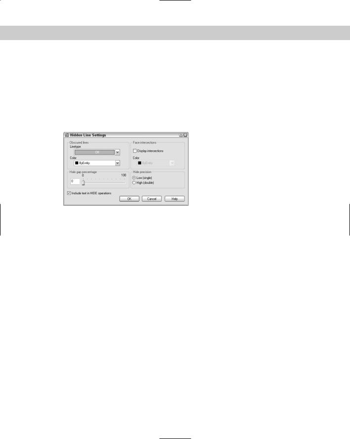
Several system variables affect the 3D display only when you use the HIDE command or the Hidden option of the SHADEMODE command. Like the HIDE command, they work on both solids and surfaces. Type hlsettings on the command line to open the Hidden Line Settings dialog box, shown in Figure 21-13.
Figure 21-13: The Hidden Line
Settings dialog box.
Here’s how to use the Hidden Line Settings dialog box:
Use the Obscured lines section to choose a linetype and color for displaying hidden lines. (This sets the OBSCUREDLTYPE system variable.) When you choose a linetype, hidden lines are shown in the linetype you choose. These linetypes are not affected as you zoom in or out. Choose from these linetypes:
Off
Solid
Dashed
Dotted
Short Dash
Medium Dash
Long Dash
Double Short Dash
Double Medium Dash
Double Long Dash
Medium Long Dash
Sparse Dot
606 Part IV Drawing in Three Dimensions
If you choose a linetype, then choose a color from the Color drop-down list (the OBSCUREDCOLOR system variable). You can choose from one of the standard color index numbers (from 1 to 255). Use the Off setting (the default) to fully hide back lines.
Use the Halo Gap Percentage section to create a gap that shortens lines at the point that they would be hidden by the HIDE command, in order to set off the lines from the unhidden portion of the model. By default, this percentage (the HALOGAP system variable) is set to 0, which creates no gap. Set the gap as a percentage of an inch — the gap doesn’t change as you zoom in or out.
Use the Display Intersections check box in the Face Intersections section to turn on the display of polylines at the intersections of 3D model faces. Then use the Color drop-down list to choose a color for the polylines.
Use the Hide Precision section of the Hidden Line Settings dialog box if you want a more exact calculation of the HIDE command results.
Check Include Text in HIDE Operations (the HIDETEXT system variable) to hide text behind other objects and for text to hide other objects. When this item is unchecked, text will not hide other objects, or be hidden, unless it has a thickness.
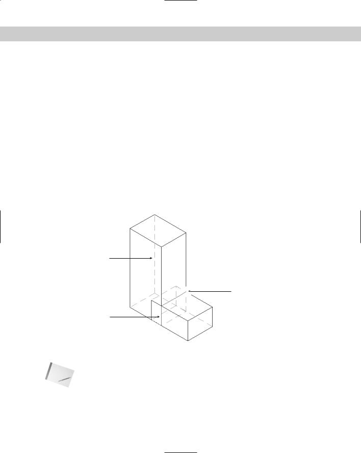
Figure 21-14 shows a model using a HALOGAP value of 15; a green, dashed line to display hidden lines; and face intersections displayed in red.
Obscured line
Halo gap
Face intersection
Figure 21-14: This model uses HALOGAP, OBSCUREDLTYPE, and
OBSCUREDCOLOR to display hidden lines.
Note The word wireframe is used in two ways. First, it means 3D objects that are created using only lines and 3D polylines. These objects have no surfaces or solidity. Second, it means surfaces and solids that are displayed as if they are created with lines and 3D polylines, such as the models in Figure 21-11. This can get confusing. In this book, I usually distinguish between wireframes and wireframe display. If the subject is surfaces and solids, the term wireframe generally means wireframe display.

Chapter 21 Specifying 3D Coordinates 607
Adding elevation to objects
Until now, all your 3D objects were based on 2D objects that were on the XY plane. In other words, their Z coordinate was zero. Although you generally don’t want objects to float in the air, you certainly may want to place one object on top of another. To do this, you need to start the object above the XY plane — you can also place objects below the XY plane — and give an object elevation, which is its Z coordinate.
To give elevation to an existing object, you can use one of two methods:
Select the object and choose Properties on the Standard toolbar. Click the Elevation property, type a new elevation in the text box, and press Enter.
Move the object(s) with the MOVE command in the Z direction.
For new objects, change the current elevation with the ELEV command as described earlier in this chapter in the discussion on thickness.
Note |
For some objects, you can use the Properties palette to change the Z coordinate. This works |
|
for circles, lines, arcs, and ellipses, but not for polylines. To elevate an entire line, you need to |
|
change the Z coordinate of both the start point and the endpoint. Choose Properties on the |
|
Standard toolbar to open the Properties palette. |
When you change the current elevation, all objects you create are drawn on that elevation. Remember to change the elevation back to zero when you want to draw on the XY plane again.
Caution |
If you specify an object snap of an object on a different elevation than your current elevation |
|
(with a different Z coordinate), AutoCAD and AutoCAD LT use the elevation of the object |
|
snap, not the current elevation. However, if you specify the first point of a 2D command, such |
|
as PLINE (to create a polyline), on the current elevation, you can use object snaps at a dif- |
|
ferent elevation for subsequent points. Because the entire polyline must be on the same ele- |
|
vation, subsequent points follow the elevation of the first point. |
STEP-BY-STEP: Working with Elevation,
Thickness, and the HIDE Command
1.Start a new drawing using the acad.dwt template.
2.Save it as ab21-03.dwg in your AutoCAD Bible folder.
3.Start the CIRCLE command. Specify the center as 6,6 and the radius as 18.
4.Do a Zoom Extents.
5.Choose Properties on the Standard toolbar. Select the circle. Click the Thickness property. In the Thickness text box, type 3 . Choose Properties again to close the Properties palette.
6.Type elev . At the Specify new default elevation <0.0000>: prompt, type 3 .
Because you just changed the existing circle’s thickness to 3, you set the elevation to 3
to place an object on top of the circle. At the Specify new default thickness <0.0000>: prompt, type 24 .