

- •Foreword
- •Preface
- •Is This Book for You?
- •How This Book Is Organized
- •How to Use This Book
- •Doing the Exercises
- •Conventions Used in This Book
- •What the Icons Mean
- •About the CD-ROM
- •Other Information
- •Contacting the Author
- •Acknowledgments
- •Contents at a Glance
- •Contents
- •Getting Acquainted with AutoCAD and AutoCAD LT
- •Starting AutoCAD and AutoCAD LT
- •Creating a New Drawing
- •Using the AutoCAD and AutoCAD LT Interface
- •Creating Your First Drawing
- •Saving a Drawing
- •Summary
- •Creating a New Drawing from a Template
- •Working with Templates
- •Opening a Drawing with Default Settings
- •Opening an Existing Drawing
- •Using an Existing Drawing as a Prototype
- •Saving a Drawing Under a New Name
- •Summary
- •The Command Line
- •Command Techniques
- •Of Mice and Pucks
- •Getting Help
- •Summary
- •Typing Coordinates
- •Displaying Coordinates
- •Picking Coordinates on the Screen
- •Locating Points
- •Summary
- •Unit Types
- •Drawing Limits
- •Understanding Scales
- •Inserting a Title Block
- •Common Setup Options
- •The MVSETUP Command
- •Summary
- •Using the LINE Command
- •Drawing Rectangles
- •Drawing Polygons
- •Creating Construction Lines
- •Creating Rays
- •Summary
- •Drawing Circles
- •Drawing Arcs
- •Creating Ellipses and Elliptical Arcs
- •Making Donuts
- •Placing Points
- •Summary
- •Panning
- •The ZOOM Command
- •Aerial View
- •Named Views
- •Tiled Viewports
- •Snap Rotation
- •User Coordinate Systems
- •Isometric Drawing
- •Summary
- •Editing a Drawing
- •Selecting Objects
- •Summary
- •Copying and Moving Objects
- •Using Construction Commands
- •Creating a Revision Cloud
- •Hiding Objects with a Wipeout
- •Double-Clicking to Edit Objects
- •Grips
- •Editing with the Properties Palette
- •Selection Filters
- •Groups
- •Summary
- •Working with Layers
- •Changing Object Color, Linetype, and Lineweight
- •Working with Linetype Scales
- •Importing Layers and Linetypes from Other Drawings
- •Matching Properties
- •Summary
- •Drawing-Level Information
- •Object-Level Information
- •Measurement Commands
- •AutoCAD’s Calculator
- •Summary
- •Creating Single-Line Text
- •Understanding Text Styles
- •Creating Multiline Text
- •Creating Tables
- •Inserting Fields
- •Managing Text
- •Finding Text in Your Drawing
- •Checking Your Spelling
- •Summary
- •Working with Dimensions
- •Drawing Linear Dimensions
- •Drawing Aligned Dimensions
- •Creating Baseline and Continued Dimensions
- •Dimensioning Arcs and Circles
- •Dimensioning Angles
- •Creating Ordinate Dimensions
- •Drawing Leaders
- •Using Quick Dimension
- •Editing Dimensions
- •Summary
- •Understanding Dimension Styles
- •Defining a New Dimension Style
- •Changing Dimension Styles
- •Creating Geometric Tolerances
- •Summary
- •Creating and Editing Polylines
- •Drawing and Editing Splines
- •Creating Regions
- •Creating Boundaries
- •Creating Hatches
- •Creating and Editing Multilines
- •Creating Dlines
- •Using the SKETCH Command
- •Digitizing Drawings with the TABLET Command
- •Summary
- •Preparing a Drawing for Plotting or Printing
- •Creating a Layout in Paper Space
- •Working with Plot Styles
- •Plotting a Drawing
- •Summary
- •Combining Objects into Blocks
- •Inserting Blocks and Files into Drawings
- •Managing Blocks
- •Using Windows Features
- •Working with Attributes
- •Summary
- •Understanding External References
- •Editing an Xref within Your Drawing
- •Controlling Xref Display
- •Managing Xrefs
- •Summary
- •Preparing for Database Connectivity
- •Connecting to Your Database
- •Linking Data to Drawing Objects
- •Creating Labels
- •Querying with the Query Editor
- •Working with Query Files
- •Summary
- •Working with 3D Coordinates
- •Using Elevation and Thickness
- •Working with the User Coordinate System
- •Summary
- •Working with the Standard Viewpoints
- •Using DDVPOINT
- •Working with the Tripod and Compass
- •Getting a Quick Plan View
- •Shading Your Drawing
- •Using 3D Orbit
- •Using Tiled Viewports
- •Defining a Perspective View
- •Laying Out 3D Drawings
- •Summary
- •Drawing Surfaces with 3DFACE
- •Drawing Surfaces with PFACE
- •Creating Polygon Meshes with 3DMESH
- •Drawing Standard 3D Shapes
- •Drawing a Revolved Surface
- •Drawing an Extruded Surface
- •Drawing Ruled Surfaces
- •Drawing Edge Surfaces
- •Summary
- •Drawing Standard Shapes
- •Creating Extruded Solids
- •Drawing Revolved Solids
- •Creating Complex Solids
- •Sectioning and Slicing Solids
- •Using Editing Commands in 3D
- •Editing Solids
- •Listing Solid Properties
- •Summary
- •Understanding Rendering
- •Creating Lights
- •Creating Scenes
- •Working with Materials
- •Using Backgrounds
- •Doing the Final Render
- •Summary
- •Accessing Drawing Components with the DesignCenter
- •Accessing Drawing Content with Tool Palettes
- •Setting Standards for Drawings
- •Organizing Your Drawings
- •Working with Sheet Sets
- •Maintaining Security
- •Keeping Track of Referenced Files
- •Handling Errors and Crashes
- •Managing Drawings from Prior Releases
- •Summary
- •Importing and Exporting Other File Formats
- •Working with Raster Images
- •Pasting, Linking, and Embedding Objects
- •Summary
- •Sending Drawings
- •Opening Drawings from the Web
- •Creating Object Hyperlinks
- •Publishing Drawings
- •Summary
- •Working with Customizable Files
- •Creating Keyboard Shortcuts for Commands
- •Customizing Toolbars
- •Customizing Tool Palettes
- •Summary
- •Creating Macros with Script Files
- •Creating Slide Shows
- •Creating Slide Libraries
- •Summary
- •Creating Linetypes
- •Creating Hatch Patterns
- •Summary
- •Creating Shapes
- •Creating Fonts
- •Summary
- •Working with Menu Files
- •Customizing a Menu
- •Summary
- •Introducing Visual LISP
- •Getting Help in Visual LISP
- •Working with AutoLISP Expressions
- •Using AutoLISP on the Command Line
- •Creating AutoLISP Files
- •Summary
- •Creating Variables
- •Working with AutoCAD Commands
- •Working with Lists
- •Setting Conditions
- •Managing Drawing Objects
- •Getting Input from the User
- •Putting on the Finishing Touches
- •Summary
- •Understanding Local and Global Variables
- •Working with Visual LISP ActiveX Functions
- •Debugging Code
- •Summary
- •Starting to Work with VBA
- •Writing VBA Code
- •Getting User Input
- •Creating Dialog Boxes
- •Modifying Objects
- •Debugging and Trapping Errors
- •Moving to Advanced Programming
- •A Final Word
- •Installing AutoCAD and AutoCAD LT
- •Configuring AutoCAD
- •Starting AutoCAD Your Way
- •Configuring a Plotter
- •System Requirements
- •Using the CD with Microsoft Windows
- •What’s on the CD
- •Troubleshooting
- •Index
352 Part II Drawing in Two Dimensions
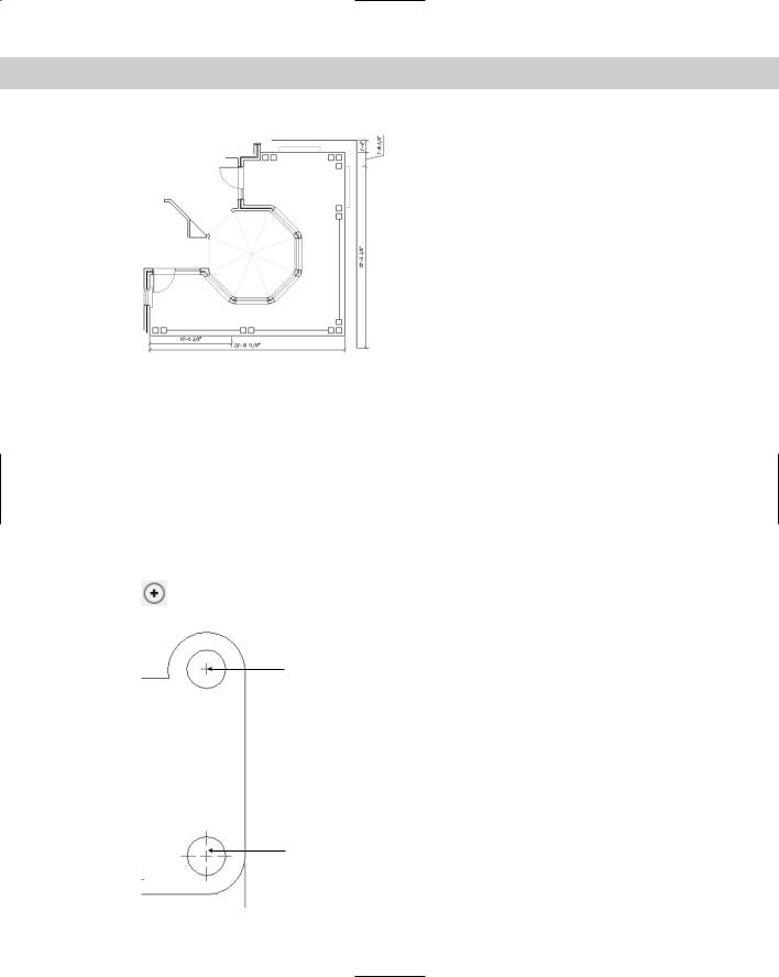
Figure 14-13: The floor plan with baseline and continued dimensions.
Dimensioning Arcs and Circles
When you dimension an arc or a circle, you measure its radius or diameter. It’s also common to mark arc and circle centers to clarify what you’re measuring. Arc and circle dimensions are most commonly used in mechanical drawings.
Marking arc and circle centers
Circle and arc centers are often marked in mechanical drawings because the center is an important aspect of a circle or arc but is not obvious without a mark. You set the size and type of mark when you create a dimension style, as explained in the next chapter. You can use a center mark (a small cross) or centerlines, as shown in Figure 14-14.
Choose Center Mark from the Dimension toolbar. At the Select arc or circle: prompt, pick the arc or circle you want to mark. The command draws the mark or lines.
Figure 14-14: Circles — one with a center mark and the other with centerlines.
Center mark
Centerlines
Chapter 14 Drawing Dimensions 353
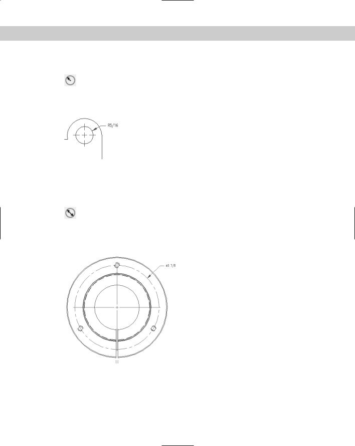
Creating radial dimensions
To dimension the radius of a circle or arc, choose Radius Dimension from the Dimension toolbar. The command responds with the Select arc or circle: prompt. Select an
arc or circle. At the Specify dimension line location or [Mtext/Text/Angle]: prompt, pick where you want the dimension line to appear. The command automatically adds an R before the measurement to indicate the radius, as shown in Figure 14-15.
Figure 14-15: This radius dimension uses a leader (a line and arrow pointing to the object) outside the circle because the circle is too small to place the dimension inside it.
You can also choose the MText, Text, or Angle option, as described in the “Drawing Linear Dimensions” section earlier in this chapter.
Creating diameter dimensions
To dimension the diameter of a circle or arc, choose Diameter Dimension from the Dimension toolbar. The command responds with the Select arc or circle: prompt.
Select an arc or circle. At the Specify dimension line location or [Mtext/Text/ Angle]: prompt, pick where you want the dimension line to appear. The command automatically adds the diameter symbol before the measurement to indicate the dimension, as shown in Figure 14-16.
Figure 14-16: A diameter dimension.
You can also choose the MText, Text, or Angle option, as described in the section “Drawing Linear Dimensions.”

354 Part II Drawing in Two Dimensions
Dimensioning Angles
You have several options for dimensioning angles. You may want to dimension the angular relationship between two lines, but the lines may intersect at their midpoints or may not intersect at all. Therefore, you need to be able to specify the vertex of the angle you want to dimension. Figure 14-17 shows an angular dimension with the points used to define it.
To create an angular dimension, choose Angular Dimension from the Dimension toolbar. The command displays the Select arc, circle, line, or <specify vertex>:
prompt and responds differently depending on what you select:
If you press Enter, the command asks for the angle vertex, the first angle endpoint, and the second angle endpoint. These three points define the angle.
If you select an arc, the command dimensions the entire arc, using the arc’s center as the angle vertex.
If you select a circle, the command uses the pick point as the first angle endpoint and the circle’s center as the angle vertex. You then see the Specify second angle endpoint: prompt. Pick a point on the circle.
If you select a line, the command asks for a second line. The command measures the angle between the two lines. If the lines don’t intersect, the command uses their implied intersection as the angle vertex.
Second angle endpoint |
First angle endpoint |
Angle vertex
Figure 14-17: An angular dimension.
Thanks to Mary Redfern of the Bethlehem Corporation,
Easton, Pennsylvania, for this drawing.
After you define the angle, the command responds with the Specify dimension arc line location or [Mtext/Text/Angle]: prompt. Pick a point for the dimension arc line — which is the same thing as a dimension line except that the command uses an arc for angular dimensions.
You can also choose the MText, Text, or Angle option, as covered in the section “Drawing Linear Dimensions.”
Chapter 14 Drawing Dimensions 355
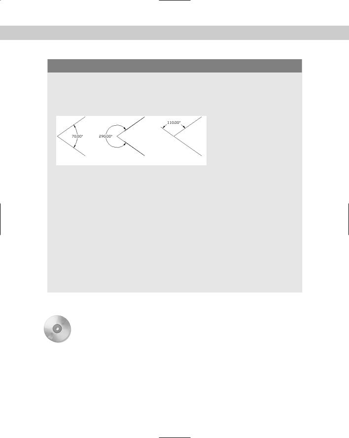
Dimensioning minor, major, and supplemental angles
When two lines meet at an angle, they create two angles — the minor angle and the major angle. The angle that is less than 180 degrees is the minor angle. The major angle is always more than 180 degrees. You can also measure the supplemental angle, which is the difference between 180 degrees and the minor angle. These angles are shown here.
Minor Angle |
Major Angle |
Supplemental Angle |
Here’s how you create each type of dimension. Start the DIMANGULAR command. The command responds with the Select arc, circle, line, or <specify vertex>: prompt.
To dimension the minor angle, select both lines. Then at the Specify dimension arc line location or [Mtext/Text/Angle]: prompt, place the dimension arc line inside the angle, as shown in the figure. (You can also press Enter, specify the angle vertex and the two lines, and place the dimension arc line inside the angle.)
To dimension the major angle, press Enter. (Do not select the lines.) At the prompts, specify the angle vertex and the two lines. At the Specify dimension arc line location or [Mtext/ Text/Angle]: prompt, place the dimension arc line outside the angle, as shown in the figure.
To dimension the supplemental angle, select both lines. At the Specify dimension arc line location or [Mtext/Text/Angle]: prompt, place the dimension arc line outside the angle, as shown in the figure.
As you can see, how you specify the angle and where you place the dimension arc line determine which angle you measure.
In the following exercise, you get to practice drawing radial, diameter, and angular dimensions.
On the |
The drawing used in the following Step-by-Step exercise on drawing radial, diameter, and |
CD-ROM |
angular dimensions, ab14-c.dwg, is in the Drawings folder on the CD-ROM. |
STEP-BY-STEP: Drawing Radial, Diameter,
and Angular Dimensions
1.Open ab14-c.dwg from your CD-ROM.
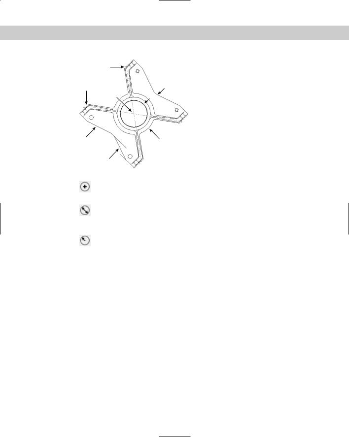
2.Save the file as ab14-04.dwg in your AutoCAD Bible folder. This is a view of a bearing housing for an industrial washing machine, as shown in Figure 14-18. OSNAP should be on. Set running object snaps to endpoint, intersection, and center. If the Dimension toolbar isn’t visible, right-click any toolbar and check Dimension.
356 Part II Drawing in Two Dimensions
4 |
|
5 |
2 |
|
|
3 |
1 |
8 |
6 |
|
7
Figure 14-18: A bearing housing for an industrial washing machine.
Thanks to Robert Mack of the Dexter Company, Fairfield, Iowa, for this drawing.
3.Choose Center Mark from the Dimension toolbar. At the Select arc or circle: prompt, pick one of the four small circles at the corners of the model. Repeat the
command for the other three circles.
4.Choose Diameter Dimension from the Dimension toolbar. At the Select arc or circle: prompt, choose the outer of the two circles at 1 in Figure 14-18. At the
Specify dimension line location or [Mtext/Text/Angle]: prompt, pick a location for the dimension line.
5.Choose Radius Dimension from the Dimension toolbar. At the Select arc or circle: prompt, choose 2 from Figure 14-18. At the Specify dimension line loca-
tion or [Mtext/Text/Angle]: prompt, pick a location for the dimension line. The line may appear to the left of the angle; try moving the cursor until the dimension appears to its right.
6. Choose Angular Dimension from the Dimension toolbar. Follow the prompts:
Select arc, circle, line, or <specify vertex>: Specify angle vertex: Pick 3 in Figure 14-18.
Specify first angle endpoint: Pick the endpoint at 4. (Press Tab if necessary until you see the endpoint tooltip.)
Specify second angle endpoint: Pick the endpoint at 5.
Specify dimension arc line location or [Mtext/Text/Angle]: Choose a location for the dimension line.
7.Repeat the DIMANGULAR command. At the Select arc, circle, line, or <specify vertex>: prompt, pick the arc at 6. At the Specify dimension arc line location or [Mtext/Text/Angle]: prompt, pick a location for the dimension line.
8.Repeat the DIMANGULAR command. At the Select arc, circle, line, or press ENTER: prompt, pick 7 in Figure 14-18. At the Second line: prompt, pick 8. At the
Dimension arc line location (Mtext/Text/Angle): prompt, pick a location for the dimension line to the left of the model.
9.Save your drawing. It should look like Figure 14-19.