

114 Part II Drawing in Two Dimensions
14.Start the ARC command. Follow the prompts:
Specify start point of arc or [Center]: Use the Endpoint object snap to pick the endpoint of the line you just drew.
Specify second point of arc or [Center/End]: Right-click and choose End.
Specify end point of arc: Choose the From object snap.
_from Base point: Use the Center object snap to pick the center of
the rightmost circle.
<Offset>: @5/8,0
Specify center point of arc or [Angle/Direction/Radius]: r Specify radius of arc: 5/8
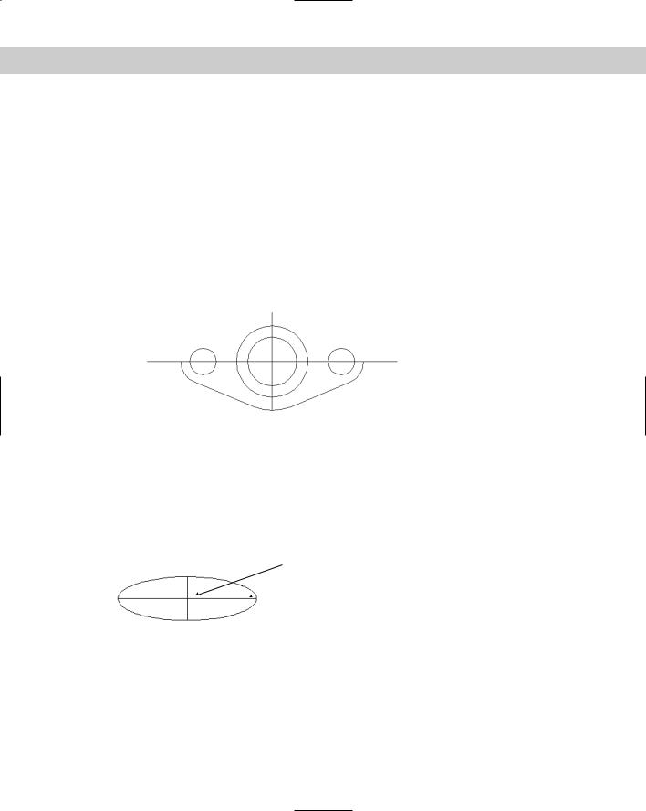
15.Save your drawing. Your drawing should look like Figure 7-6. You can complete this drawing in Chapter 10 by creating a mirror image.
Figure 7-6: The partially completed sealing plate, created by using lines, circles, and arcs.
Creating Ellipses and Elliptical Arcs
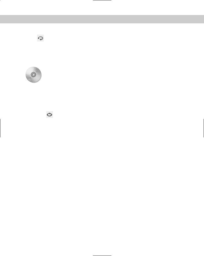
You can create ellipses (ovals), and you can also create elliptical arcs, which are partial ellipses. Like a circle, an ellipse has a center. The difference, of course, is that an ellipse has a longer radius along its major axis and a shorter radius along its minor axis, as shown in Figure 7-7.
Center
 Major axis
 Minor axis
Figure 7-7: The parts of an ellipse.
Understanding ellipse options
You can draw ellipses by defining a center first. Another option is to define the axis endpoints first. If you want to draw an elliptical arc, you must specify the start and end angle.

Chapter 7 Drawing Curves and Points 115
Ellipses
The default option is to specify endpoints 1 and 2 of the first axis. Then you specify the second axis distance, which is the distance from the first axis line to the circumference along the second axis. Instead of specifying a second axis distance, you can choose the Rotation option.
The Rotation option defines the minor axis by defining an angle from 0 degrees to 90 degrees, which is the ratio of the major axis to the minor axis. (Actually, the command only accepts up to 89.4 degrees.) When the angle is 0, you get a circle. As the angle increases, the ellipse gets flatter and flatter until you reach 89.4 degrees. A 45-degree angle results in a minor axis whose length is the square root of the major-axis length.
Instead of specifying endpoints, you can type c to specify the center of the ellipse. Then specify the endpoint of the first axis, which can be either the major or the minor axis. Finally, specify the other axis distance, which is the radius from the center to the circumference along the second axis. Again, instead of specifying the second axis distance, you can define the ellipse by using the Rotation option.
Elliptical arcs
To draw an elliptical arc, use the Arc option of the ELLIPSE command. In AutoCAD only, there is an Ellipse Arc button on the Draw toolbar. (This button is equivalent to choosing the Arc option of the ELLIPSE command and offers no additional functionality.) The first prompts are the same as for an ellipse because you must first define the ellipse. Then the command continues with the Specify start angle or [Parameter]: prompt, offering the following options:
Start angle: This option is the default. Specify the start angle, which the command redefines to start along the major axis. The command responds with the Specify end angle or [Parameter/Included angle]: prompt.
End angle: Specify the end angle to complete the ellipse arc.
Included angle: After specifying the start angle, you can complete the arc by specifying the included angle from the start point to the endpoint, going counterclockwise.
Parameter: Choose this option to define the arc portion by the ellipse’s area rather than its included angle (which defines the arc portion by its circumference). The command responds with the Specify start parameter or [Angle]: and Specify end parameter or [Angle/Included angle]: prompts. By typing in angles, you define the percent of the full ellipse’s area that you want to include. (For example, starting at 15 degrees and ending at 105 degrees includes 90 degrees and therefore draws one-quarter of an ellipse.) The options in brackets let you return to regular angle specification.
Drawing ellipses
To draw an ellipse, choose Ellipse from the Draw toolbar. In addition to the information the command explicitly requests in the prompts, you need to know the angle of the first axis that you define. Not all ellipses are horizontal or vertical. You control this when you stip-
ulate the second point of the first axis. The second axis is automatically perpendicular to the first axis.
116 Part II Drawing in Two Dimensions
To draw an elliptical arc, choose Ellipse Arc from the Draw toolbar (in AutoCAD) or use the Arc option of the ELLIPSE command. When you draw an elliptical arc, the command
introduces a helpful but sometimes confusing feature: While you’re defining the arc angles, the command redefines 0 degrees along the major axis. This helps you define the included angle in an orientation that relates to the ellipse, rather than the usual orientation where 0 degrees is to the right.
In this exercise, you practice drawing ellipses and elliptical arcs.
On the |
The drawing used in the following Step-by-Step exercise on drawing ellipses and elliptical |
CD-ROM |
arcs, ab07-c.dwg, is in the Drawings folder on the CD-ROM. |
STEP-BY-STEP: Drawing Ellipses and Elliptical Arcs
1.Open ab07-c.dwg from the CD-ROM.
2.Save the file as ab07-03.dwg in your AutoCAD Bible folder. The drawing shows an empty conference room. Snap is on, set to 6". Check that OSNAP is on with a running object snap set for endpoint only.
3.Choose Ellipse from the Draw toolbar. At the Specify axis endpoint of ellipse or [Arc/Center]: prompt, right-click and choose Center. At the
Specify center of ellipse: prompt, choose 8',10', which is a snap point. At the Specify endpoint of axis: prompt, move the cursor to the right until the coordinates read 3'<0 and click. (If necessary, press F6 until you see polar coordinates.) At the
Specify distance to other axis or [Rotation]: prompt, move the cursor up until the coordinates read 6'6"<90 and click. This completes the conference table.
4.Choose Ellipse from the Draw toolbar. Follow the prompts:
Specify axis endpoint of ellipse or [Arc/Center]: Right-click and choose Arc.
Specify axis endpoint of elliptical arc or [Center]: Right-click and choose Center.
Specify center of elliptical arc: Pick 8',3', a snap point.
Specify endpoint of axis: Move the cursor to the right until the coordinates read 1'<0 and pick.
Specify distance to other axis or [Rotation]: Move the cursor up
until the coordinates read 6"<90 and pick.
Specify start angle or [Parameter]: 162
Specify end angle or [Parameter/Included angle]: 18
5.Turn off ORTHO. Start the LINE command. At the Specify first point: prompt, use the Endpoint running object snap and pick the right side of the elliptical arc. At the Specify next point or [Undo]: prompt, press F6 to change to dynamic absolute coordinates (if necessary) and pick the snap point 8'6",3'. (You may have to turn off OSNAP in the middle of the command to pick this point and avoid getting an endpoint.) End the LINE command.
6.Start the LINE command. At the Specify first point: prompt, choose the Endpoint object snap and pick the left side of the ellipse arc. At the Specify next point or [Undo]: prompt, pick the snap point 7'6",3'. End the LINE command.
7.Choose Ellipse again. Follow the prompts:

Chapter 7 Drawing Curves and Points 117
Specify axis endpoint of ellipse or [Arc/Center]: Right-click and choose Arc.
Specify axis endpoint of elliptical arc or [Center]: Use the Endpoint object snap to pick the free endpoint of the line on the right. Specify other endpoint of axis: Use the Endpoint object snap to pick the free endpoint of the line on the left.
Specify distance to other axis or [Rotation]: @3<90
Specify start angle or [Parameter]: Use the Endpoint object snap to pick the free endpoint of the line on the right.
Specify end angle or [Parameter/Included angle]: Use Endpoint object snap to pick the free endpoint of the line on the left.
8.Choose Ellipse from the Draw toolbar. At the Specify axis endpoint of ellipse or [Arc/Center]: prompt, pick point 2',18', a snap point. At the Specify other endpoint of axis: prompt, pick point 2',16', also a snap point. At the Specify distance to other axis or [Rotation]: prompt, move the cursor to the right until the coordinates read 6"<0. (Press F6 twice if necessary.) This is also a snap point. Click the mouse button to complete the small side table.
9.Save your drawing. It should look like Figure 7-8.
Figure 7-8: The conference room with a conference table, a chair, and a side table.
Making Donuts
A donut is a wide polyline that looks like two concentric circles. You define a diameter for the inner and outer circles. AutoCAD and AutoCAD LT accept both DONUT and DOUGHNUT if you type in the command. Donuts are often used in electrical drawings to create symbols. If the inner circle’s radius is zero, you create a filled-in circle.
118 Part II Drawing in Two Dimensions
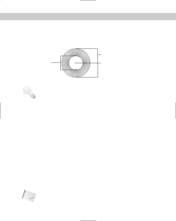
The setting of the FILL command determines whether the donut is filled. Type fill and type on or off . FILL is on by default. Turning FILL off displays a radial pattern of lines, as shown in Figure 7-9. Type regen or choose View Regen to update existing donuts to the new FILL setting.
Outside diameter
Inside diameter |
Center |
|
Figure 7-9: The parts of a donut, shown with FILL off. |
Tip |
If you have many filled objects in your drawing, your drawing may take some time to display. |
|
You can save time by turning FILL off while you draw. Then turn FILL on just before you need |
|
to print or plot the drawing. |
|
Understanding DONUT options |
|
The DONUT command has the following prompts: |
Specify inside diameter of donut <0.5000>: Type the diameter of the inside circle or pick two points to specify the inside diameter. The number in brackets is the last inside diameter that you defined or 0.5 if you haven’t previously used the DONUT command in this drawing session.
Specify outside diameter of donut <1.0000>: Type the diameter of the outside circle or pick two points to specify the outside diameter. The outside diameter must be larger than the inside diameter. The number in brackets is the last outside diameter that you defined or 1.0 if you haven’t previously used the DONUT command in this drawing session.
Specify second point: If you define the inside or outside diameter by picking a point, the command asks for a second point. Use this technique if you’re using object snaps to define the diameters.
Specify center of donut or <exit>: Specify the center of the donut. Pressing Enter ends the command.
Drawing donuts
Drawing donuts is relatively easy. Choose Draw Donut. Then specify the inner and outer diameters and the center. The DONUT command continues to prompt for centers so you can place additional donuts. Press Enter to end the command.
Note |
You can use the hatch feature to fill in any object with a solid fill, with a great deal more flex- |
|
ibility in the shape of your objects. (Chapter 16 discusses hatching.) As a result, the DONUT |
|
command is not as essential as it once was. |