

- •Foreword
- •Preface
- •Is This Book for You?
- •How This Book Is Organized
- •How to Use This Book
- •Doing the Exercises
- •Conventions Used in This Book
- •What the Icons Mean
- •About the CD-ROM
- •Other Information
- •Contacting the Author
- •Acknowledgments
- •Contents at a Glance
- •Contents
- •Getting Acquainted with AutoCAD and AutoCAD LT
- •Starting AutoCAD and AutoCAD LT
- •Creating a New Drawing
- •Using the AutoCAD and AutoCAD LT Interface
- •Creating Your First Drawing
- •Saving a Drawing
- •Summary
- •Creating a New Drawing from a Template
- •Working with Templates
- •Opening a Drawing with Default Settings
- •Opening an Existing Drawing
- •Using an Existing Drawing as a Prototype
- •Saving a Drawing Under a New Name
- •Summary
- •The Command Line
- •Command Techniques
- •Of Mice and Pucks
- •Getting Help
- •Summary
- •Typing Coordinates
- •Displaying Coordinates
- •Picking Coordinates on the Screen
- •Locating Points
- •Summary
- •Unit Types
- •Drawing Limits
- •Understanding Scales
- •Inserting a Title Block
- •Common Setup Options
- •The MVSETUP Command
- •Summary
- •Using the LINE Command
- •Drawing Rectangles
- •Drawing Polygons
- •Creating Construction Lines
- •Creating Rays
- •Summary
- •Drawing Circles
- •Drawing Arcs
- •Creating Ellipses and Elliptical Arcs
- •Making Donuts
- •Placing Points
- •Summary
- •Panning
- •The ZOOM Command
- •Aerial View
- •Named Views
- •Tiled Viewports
- •Snap Rotation
- •User Coordinate Systems
- •Isometric Drawing
- •Summary
- •Editing a Drawing
- •Selecting Objects
- •Summary
- •Copying and Moving Objects
- •Using Construction Commands
- •Creating a Revision Cloud
- •Hiding Objects with a Wipeout
- •Double-Clicking to Edit Objects
- •Grips
- •Editing with the Properties Palette
- •Selection Filters
- •Groups
- •Summary
- •Working with Layers
- •Changing Object Color, Linetype, and Lineweight
- •Working with Linetype Scales
- •Importing Layers and Linetypes from Other Drawings
- •Matching Properties
- •Summary
- •Drawing-Level Information
- •Object-Level Information
- •Measurement Commands
- •AutoCAD’s Calculator
- •Summary
- •Creating Single-Line Text
- •Understanding Text Styles
- •Creating Multiline Text
- •Creating Tables
- •Inserting Fields
- •Managing Text
- •Finding Text in Your Drawing
- •Checking Your Spelling
- •Summary
- •Working with Dimensions
- •Drawing Linear Dimensions
- •Drawing Aligned Dimensions
- •Creating Baseline and Continued Dimensions
- •Dimensioning Arcs and Circles
- •Dimensioning Angles
- •Creating Ordinate Dimensions
- •Drawing Leaders
- •Using Quick Dimension
- •Editing Dimensions
- •Summary
- •Understanding Dimension Styles
- •Defining a New Dimension Style
- •Changing Dimension Styles
- •Creating Geometric Tolerances
- •Summary
- •Creating and Editing Polylines
- •Drawing and Editing Splines
- •Creating Regions
- •Creating Boundaries
- •Creating Hatches
- •Creating and Editing Multilines
- •Creating Dlines
- •Using the SKETCH Command
- •Digitizing Drawings with the TABLET Command
- •Summary
- •Preparing a Drawing for Plotting or Printing
- •Creating a Layout in Paper Space
- •Working with Plot Styles
- •Plotting a Drawing
- •Summary
- •Combining Objects into Blocks
- •Inserting Blocks and Files into Drawings
- •Managing Blocks
- •Using Windows Features
- •Working with Attributes
- •Summary
- •Understanding External References
- •Editing an Xref within Your Drawing
- •Controlling Xref Display
- •Managing Xrefs
- •Summary
- •Preparing for Database Connectivity
- •Connecting to Your Database
- •Linking Data to Drawing Objects
- •Creating Labels
- •Querying with the Query Editor
- •Working with Query Files
- •Summary
- •Working with 3D Coordinates
- •Using Elevation and Thickness
- •Working with the User Coordinate System
- •Summary
- •Working with the Standard Viewpoints
- •Using DDVPOINT
- •Working with the Tripod and Compass
- •Getting a Quick Plan View
- •Shading Your Drawing
- •Using 3D Orbit
- •Using Tiled Viewports
- •Defining a Perspective View
- •Laying Out 3D Drawings
- •Summary
- •Drawing Surfaces with 3DFACE
- •Drawing Surfaces with PFACE
- •Creating Polygon Meshes with 3DMESH
- •Drawing Standard 3D Shapes
- •Drawing a Revolved Surface
- •Drawing an Extruded Surface
- •Drawing Ruled Surfaces
- •Drawing Edge Surfaces
- •Summary
- •Drawing Standard Shapes
- •Creating Extruded Solids
- •Drawing Revolved Solids
- •Creating Complex Solids
- •Sectioning and Slicing Solids
- •Using Editing Commands in 3D
- •Editing Solids
- •Listing Solid Properties
- •Summary
- •Understanding Rendering
- •Creating Lights
- •Creating Scenes
- •Working with Materials
- •Using Backgrounds
- •Doing the Final Render
- •Summary
- •Accessing Drawing Components with the DesignCenter
- •Accessing Drawing Content with Tool Palettes
- •Setting Standards for Drawings
- •Organizing Your Drawings
- •Working with Sheet Sets
- •Maintaining Security
- •Keeping Track of Referenced Files
- •Handling Errors and Crashes
- •Managing Drawings from Prior Releases
- •Summary
- •Importing and Exporting Other File Formats
- •Working with Raster Images
- •Pasting, Linking, and Embedding Objects
- •Summary
- •Sending Drawings
- •Opening Drawings from the Web
- •Creating Object Hyperlinks
- •Publishing Drawings
- •Summary
- •Working with Customizable Files
- •Creating Keyboard Shortcuts for Commands
- •Customizing Toolbars
- •Customizing Tool Palettes
- •Summary
- •Creating Macros with Script Files
- •Creating Slide Shows
- •Creating Slide Libraries
- •Summary
- •Creating Linetypes
- •Creating Hatch Patterns
- •Summary
- •Creating Shapes
- •Creating Fonts
- •Summary
- •Working with Menu Files
- •Customizing a Menu
- •Summary
- •Introducing Visual LISP
- •Getting Help in Visual LISP
- •Working with AutoLISP Expressions
- •Using AutoLISP on the Command Line
- •Creating AutoLISP Files
- •Summary
- •Creating Variables
- •Working with AutoCAD Commands
- •Working with Lists
- •Setting Conditions
- •Managing Drawing Objects
- •Getting Input from the User
- •Putting on the Finishing Touches
- •Summary
- •Understanding Local and Global Variables
- •Working with Visual LISP ActiveX Functions
- •Debugging Code
- •Summary
- •Starting to Work with VBA
- •Writing VBA Code
- •Getting User Input
- •Creating Dialog Boxes
- •Modifying Objects
- •Debugging and Trapping Errors
- •Moving to Advanced Programming
- •A Final Word
- •Installing AutoCAD and AutoCAD LT
- •Configuring AutoCAD
- •Starting AutoCAD Your Way
- •Configuring a Plotter
- •System Requirements
- •Using the CD with Microsoft Windows
- •What’s on the CD
- •Troubleshooting
- •Index

656 Part IV Drawing in Three Dimensions
Tip |
As soon as you have a separate layer for the hidden portion of the model, you can modify |
|
that layer’s color and/or linetype to show the hidden lines in a contrasting color or linetype. |
Summary
In this chapter, I covered all the ways to view your 3D drawing. You read about:
Using the standard viewpoints on the Viewpoint flyout for a quick look
Utilizing the DDVPOINT command to specify exact angles
Using the tripod and compass for flexibility
Using the PLAN command to quickly return you to plan view
Shading your drawing in one of several modes — these shading modes persist until you turn them off.
Applying 3D orbit to view your model from any position. You can zoom and pan, create parallel and perspective views, and set clipping planes. You can also create a continuously moving orbit.
Using the DVIEW command to let you create parallel and perspective views. You set the camera and target where you can create front and back clipping planes.
Employing the three commands — SOLVIEW, SOLDRAW, and SOLPROF — that help you lay out views of a 3D drawing for plotting
In the next chapter, I explain how to create 3D surfaces.
|
|
|

Creating 3D
Surfaces
In this chapter, you learn to create all types of surfaces, also called meshes. Surfaces have a great advantage over 3D wireframe models
because you can hide back surfaces and create shaded images for easier visualization of your models. Surfaces also enable you to create unusual shapes, such as for topological maps or free-form objects.
This entire chapter applies to AutoCAD only. For information on surfaces that AutoCAD LT can create, see Chapter 21.
Figure 23-1 shows a lamp created by using surfaces.
Figure 23-1: A lamp created with surfaces.
23C H A P T E R
In This Chapter
Drawing surfaces with 3DFACE and PFACE
Creating 3D polygon meshes
Drawing standard 3D shapes
Drawing a revolved surface
Creating extruded, ruled, and edge surfaces
658 Part IV Drawing in Three Dimensions
You cannot obtain information about physical properties — such as mass, center of gravity, and so on — from surfaces. Such information can be obtained only from 3D solids, which are covered in the next chapter.
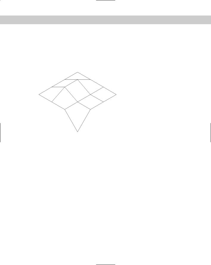
AutoCAD approximates curved surfaces by creating a mesh of planes at varying angles. You see the planes because AutoCAD displays them using a web of intersecting lines. AutoCAD defines the mesh by its vertices — where the lines intersect. Figure 23-2 shows a mesh with its vertices.
Figure 23-2: A surface mesh.
When working with surfaces you may want to display the Surfaces toolbar. Right-click any toolbar and choose Surfaces.
Drawing Surfaces with 3DFACE
Two-dimensional objects are often used to create three-dimensional models. In Chapter 21, I discuss how you can use 2D solids (the SOLID command), wide polylines, and circles to make horizontal surfaces when you add a thickness to them. In fact, the SOLID command is so useful in 3D that you can find its icon on the Surfaces toolbar.
You can also use regions in 3D drawings. Although regions are 2D objects and cannot be given a thickness, when you use the HIDE command, AutoCAD displays the region as a surface. When the drawing is regenerated to a wireframe display, the region is displayed as a wireframe again, losing its surface properties.
Another option is to use 3DFACE, which is a true 3D command. 3DFACE creates threeor foursided surfaces that can be in any plane. You can place surfaces together to make a many-sided surface. While AutoCAD draws lines between these surfaces, you can make the lines invisible to create the effect of a seamless surface. You define the surface by specifying the points that create the corners of the surface. As a result, a 3D face cannot have any curves. 3DFACE only creates surfaces — you cannot give a thickness to a 3D face. However, you can create a 3D solid from a 3D face using the EXTRUDE command. 3D solids are covered in the next chapter.
Chapter 23 Creating 3D Surfaces 659
Using the 3DFACE command
To create a 3D face, choose 3D Face from the Surfaces toolbar. AutoCAD prompts you for first, second, third, and fourth points. You must specify points clockwise or counterclock-
wise, not in the zigzag fashion required by the 2D SOLID command. When creating a 3D face:
Press Enter at the Specify fourth point or [Invisible] <create three-sided face>: prompt to create a three-sided surface. Then press Enter again to end the command.
To create a four-sided surface, specify a fourth point. AutoCAD repeats the Specify
third point or [Invisible] <exit>: prompt. Press Enter to end the command.
To create surfaces of more than four sides, continue to specify points. AutoCAD repeats the thirdand fourth-point prompts until you press Enter — twice after a third point or once after a fourth point.
As you continue to add faces, the last edge created by the third and fourth points becomes the first edge of the new face so that adding a face requires only two additional points.
Tip |
It often helps to prepare for a complex 3D face by creating 2D objects for some or all of the |
|
faces. You can then use Endpoint object snaps to pick the points of the 3D face. Place these |
|
2D objects on a unique layer, such as Frames or Const. |
Making 3D face edges invisible
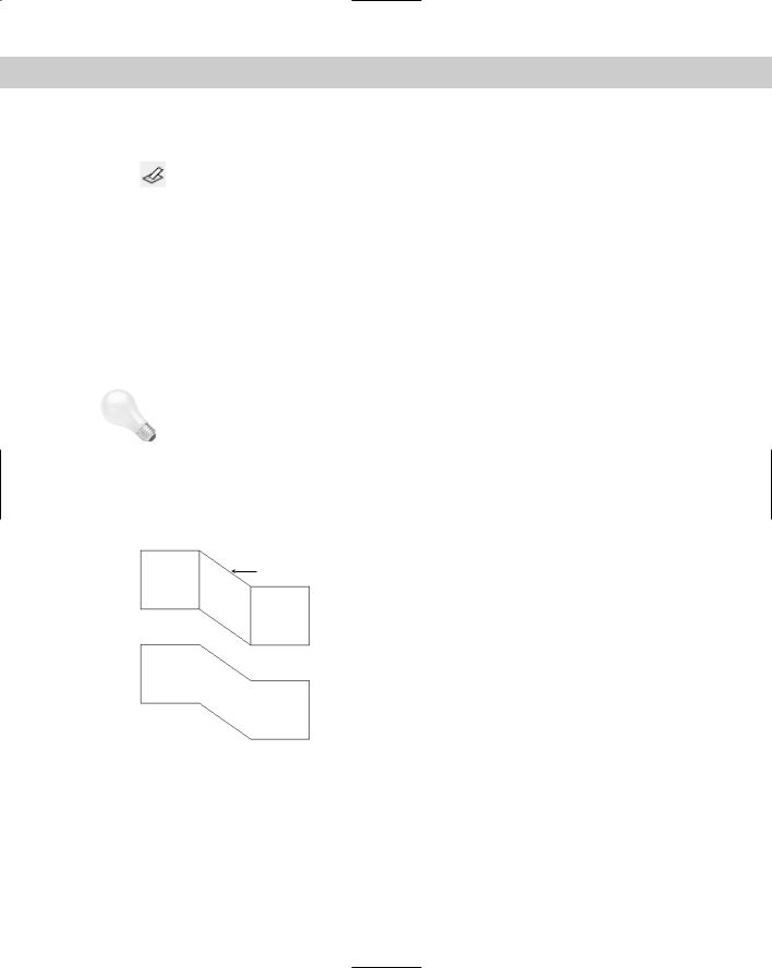
Making edges invisible makes a series of 3D faces look like one 3D face. Figure 23-3 shows three 3D faces with and without internal seams.
|
Figure 23-3: You can make internal edges |
All edges visible |
of a 3D face invisible. |
 Internal edges invisible
You can control the visibility of 3D face edges in several ways.
Controlling visibility during 3D face creation
While you’re drawing the 3D face, you can right-click and choose Invisible before each edge. Then specify the next point. However, it’s sometimes difficult to predict exactly where to indicate the invisible edge.
660 Part IV Drawing in Three Dimensions
Using the EDGE command
After creating the entire 3D face, you can use the EDGE command. The sole purpose of the EDGE command is to make 3D face edges visible and invisible — this is probably the easiest way to control the visibility of 3D face edges.
Choose Edge from the Surfaces toolbar. At the Specify edge of 3dface to toggle visibility or [Display]: prompt, select a visible edge that you want to make invisi-
ble. AutoCAD repeats the prompt so that you can select additional edges. Press Enter to make the edges invisible. Although a visible edge might actually be two edges belonging to two adjacent 3D faces, EDGE makes them both invisible.
To make invisible edges visible, right-click and choose the Display option. AutoCAD displays all the edges in dashed lines and shows the Enter selection method for display of hidden edges [Select/All] <All>: prompt. Press Enter to display all the edges or use the Select option to select 3D faces (you can use windows for selection). Either way, you see the edges of the 3D face you want to edit. AutoCAD then repeats the Specify edge of
3dface to toggle visibility or [Display]: prompt. You can now select the edge you want to make visible. Press Enter to end the command and make the edge visible.
Using the Properties palette
After creating one or more 3D faces, you can also open the Properties palette (choose Properties on the Standard toolbar) and select one 3D face. You can choose more than one, but the results are difficult to predict.
Using this palette to edit 3D face edge visibility presents two difficulties. First, you have no easy way of knowing which edge is which, because the palette only labels them Edge 1, 2, 3, and 4. Second, although the EDGE command makes both edges of adjacent 3D faces visible or invisible, the Properties palette does not. You need to use it for each adjacent face. The best method is to use the EDGE command to control visibility of 3D face edges.
Using the SPLFRAME system variable
Setting the SPLFRAME system variable to 1 and then regenerating the drawing makes all 3D face edges visible. (The SPLFRAME system variable also affects the display of spline-fit polylines, hence its name.) To return edges to their original setting, set SPLFRAME to 0 and do a REGEN.
On the |
The drawing used in the following Step-by-Step exercise on drawing 3D faces, ab23-a.dwg, |
CD-ROM |
is in the Drawings folder on the CD-ROM. |
STEP-BY-STEP: Drawing 3D Faces
1.Open ab23-a.dwg from the CD-ROM.
2.Save it as ab23-01.dwg in your AutoCAD Bible folder. This is a blank drawing with architectural units. Turn on ORTHO. OSNAP should be on. Set running object snaps for endpoints and midpoints. If the Surfaces toolbar is not displayed, right-click any toolbar, and check Surfaces.

Chapter 23 Creating 3D Surfaces 661
3. Choose 3D Face from the Surfaces toolbar. Follow the prompts:
Specify first point or [Invisible]: 6,6 Specify second point or [Invisible]: @20,0
Specify third point or [Invisible] <exit>: @0,2'
Specify fourth point or [Invisible] <create three-sided face>:
@–20,0
Specify third point or [Invisible] <exit>:
4.Start the COPY command. Follow the prompts:
Select objects: Select the 3D face. Select objects:
Specify base point or displacement, or [Multiple]: Right-click and choose Multiple.
Specify base point: Pick any point.
Specify second point of displacement or <use first point as displacement>: @0,0,1.5'
Specify second point of displacement or <use first point as displacement>: @0,0,3'
Specify second point of displacement or <use first point as displacement>:
You don’t see any difference because you’re looking at the three 3D faces in plan view and they’re on top of each other.
5.Choose View 3D Views SE Isometric. Your drawing should look like Figure 23-4. You now have the top, bottom, and middle shelf of the cabinet.
3
6
2
7
4
5
1
8
Figure 23-4: The three 3D faces from an isometric viewpoint.
6. Start the 3DFACE command again. Follow the prompts:

662 Part IV Drawing in Three Dimensions
Specify first point or [Invisible]: Pick the endpoint at 1 in Figure 23-4.
Specify second point or [Invisible]: Pick the endpoint at 2. Specify third point or [Invisible] <exit>: Pick the endpoint at 3. Specify fourth point or [Invisible] <create three-sided face>: Pick the endpoint at 4.
Specify third point or [Invisible] <exit>: Pick the endpoint at 5. Specify fourth point or [Invisible] <create three-sided face>: Pick the endpoint at 6.
Specify third point or [Invisible] <exit>: Pick the endpoint at 7. Specify fourth point or [Invisible] <create three-sided face>: Pick the endpoint at 8.
Specify third point or [Invisible] <exit>:
7.To draw the door of the cabinet, change the current layer to CONST. Start the LINE command and draw a line from 2 in Figure 23-4 to @18<225. End the LINE command. Now start the COPY command and copy the line from 2 to 1. These two construction lines frame the door.
8.To make it easier to work on the door, choose Tools New UCS 3 Point. Follow the prompts:
Specify new origin point <0,0,0>: Pick the left endpoint of the bottom construction line.
Specify point on positive portion of X-axis <-0'-5 3/4",-0'-6 3/4", 0'-0">: Pick 1 in Figure 23-4.
Specify point on positive-Y portion of the UCS XY plane <-0'-7 7/16", -0'-6",0'-">: Pick the left endpoint of the top construction line.
9.Start the LINE command again. Follow the prompts:
Specify first point: Choose the From object snap.
Base point: Pick the left endpoint of the top construction line.
<Offset>: @3,–3
Specify next point or [Undo]: Move the cursor to the right and type
12 .
Specify next point or [Undo]: Move the cursor down and type 30 .
Specify next point or [Close/Undo]: Move the cursor to the left and type 12 .
Specify next point or [Close/Undo]: c
Your drawing should look like Figure 23-5.
10.Change the current layer to 0. Choose 3D Face from the Surfaces toolbar. Follow the prompts:
Specify first point or [Invisible]: Pick the endpoint at 1 in Figure 23-5.
Specify second point or [Invisible]: Pick the endpoint at 2 in Figure 23-5.
Specify third point or [Invisible] <exit>: Pick the endpoint at 3. Specify fourth point or [Invisible] <create three-sided face>: Pick the endpoint at 4 in Figure 23-5. Notice the edge lines between 1 and 2 and between 3 and 4.

Chapter 23 Creating 3D Surfaces 663
Specify third point or [Invisible] <exit>: Right-click and choose Invisible. Pick the endpoint at 5 in Figure 23-5.
Specify fourth point or [Invisible] <create three-sided face>: Pick the endpoint at 6.
Specify third point or [Invisible] <exit>: Right-click and choose Invisible. Pick the endpoint at 7.
Specify fourth point or [Invisible] <create three-sided face>: Pick the endpoint at 8.
Specify third point or [Invisible] <exit>: Pick the endpoint at 1 in Figure 23-5.
Specify fourth point or [Invisible] <create three-sided face>: Pick the endpoint at 2.
Specify third point or [Invisible] <exit>:
5 8
 6
6  7
7
3
2
 4 1
4 1
Figure 23-5: The partially completed cabinet.
11.Choose Edge from the Surfaces toolbar. At the Specify edge of 3dface to toggle visibility or [Display]: prompt, pick the edge between 1 and 2
and then the edge between 3 and 4. (A midpoint marker and SnapTip appear.) Press Enter. The edges disappear.
12.Choose Tools New UCS World.
13.Choose View 3D Views Viewpoint Presets to open the Viewpoint Presets dialog box. Set the From: X Axis angle to 200 degrees. Set the XY Plane angle to 35 degrees. Choose OK.
14.Choose View Hide to see the result. You can clearly see through the window of the cabinet door.
15.Save your drawing. It should look like Figure 23-6.