

- •Foreword
- •Preface
- •Is This Book for You?
- •How This Book Is Organized
- •How to Use This Book
- •Doing the Exercises
- •Conventions Used in This Book
- •What the Icons Mean
- •About the CD-ROM
- •Other Information
- •Contacting the Author
- •Acknowledgments
- •Contents at a Glance
- •Contents
- •Getting Acquainted with AutoCAD and AutoCAD LT
- •Starting AutoCAD and AutoCAD LT
- •Creating a New Drawing
- •Using the AutoCAD and AutoCAD LT Interface
- •Creating Your First Drawing
- •Saving a Drawing
- •Summary
- •Creating a New Drawing from a Template
- •Working with Templates
- •Opening a Drawing with Default Settings
- •Opening an Existing Drawing
- •Using an Existing Drawing as a Prototype
- •Saving a Drawing Under a New Name
- •Summary
- •The Command Line
- •Command Techniques
- •Of Mice and Pucks
- •Getting Help
- •Summary
- •Typing Coordinates
- •Displaying Coordinates
- •Picking Coordinates on the Screen
- •Locating Points
- •Summary
- •Unit Types
- •Drawing Limits
- •Understanding Scales
- •Inserting a Title Block
- •Common Setup Options
- •The MVSETUP Command
- •Summary
- •Using the LINE Command
- •Drawing Rectangles
- •Drawing Polygons
- •Creating Construction Lines
- •Creating Rays
- •Summary
- •Drawing Circles
- •Drawing Arcs
- •Creating Ellipses and Elliptical Arcs
- •Making Donuts
- •Placing Points
- •Summary
- •Panning
- •The ZOOM Command
- •Aerial View
- •Named Views
- •Tiled Viewports
- •Snap Rotation
- •User Coordinate Systems
- •Isometric Drawing
- •Summary
- •Editing a Drawing
- •Selecting Objects
- •Summary
- •Copying and Moving Objects
- •Using Construction Commands
- •Creating a Revision Cloud
- •Hiding Objects with a Wipeout
- •Double-Clicking to Edit Objects
- •Grips
- •Editing with the Properties Palette
- •Selection Filters
- •Groups
- •Summary
- •Working with Layers
- •Changing Object Color, Linetype, and Lineweight
- •Working with Linetype Scales
- •Importing Layers and Linetypes from Other Drawings
- •Matching Properties
- •Summary
- •Drawing-Level Information
- •Object-Level Information
- •Measurement Commands
- •AutoCAD’s Calculator
- •Summary
- •Creating Single-Line Text
- •Understanding Text Styles
- •Creating Multiline Text
- •Creating Tables
- •Inserting Fields
- •Managing Text
- •Finding Text in Your Drawing
- •Checking Your Spelling
- •Summary
- •Working with Dimensions
- •Drawing Linear Dimensions
- •Drawing Aligned Dimensions
- •Creating Baseline and Continued Dimensions
- •Dimensioning Arcs and Circles
- •Dimensioning Angles
- •Creating Ordinate Dimensions
- •Drawing Leaders
- •Using Quick Dimension
- •Editing Dimensions
- •Summary
- •Understanding Dimension Styles
- •Defining a New Dimension Style
- •Changing Dimension Styles
- •Creating Geometric Tolerances
- •Summary
- •Creating and Editing Polylines
- •Drawing and Editing Splines
- •Creating Regions
- •Creating Boundaries
- •Creating Hatches
- •Creating and Editing Multilines
- •Creating Dlines
- •Using the SKETCH Command
- •Digitizing Drawings with the TABLET Command
- •Summary
- •Preparing a Drawing for Plotting or Printing
- •Creating a Layout in Paper Space
- •Working with Plot Styles
- •Plotting a Drawing
- •Summary
- •Combining Objects into Blocks
- •Inserting Blocks and Files into Drawings
- •Managing Blocks
- •Using Windows Features
- •Working with Attributes
- •Summary
- •Understanding External References
- •Editing an Xref within Your Drawing
- •Controlling Xref Display
- •Managing Xrefs
- •Summary
- •Preparing for Database Connectivity
- •Connecting to Your Database
- •Linking Data to Drawing Objects
- •Creating Labels
- •Querying with the Query Editor
- •Working with Query Files
- •Summary
- •Working with 3D Coordinates
- •Using Elevation and Thickness
- •Working with the User Coordinate System
- •Summary
- •Working with the Standard Viewpoints
- •Using DDVPOINT
- •Working with the Tripod and Compass
- •Getting a Quick Plan View
- •Shading Your Drawing
- •Using 3D Orbit
- •Using Tiled Viewports
- •Defining a Perspective View
- •Laying Out 3D Drawings
- •Summary
- •Drawing Surfaces with 3DFACE
- •Drawing Surfaces with PFACE
- •Creating Polygon Meshes with 3DMESH
- •Drawing Standard 3D Shapes
- •Drawing a Revolved Surface
- •Drawing an Extruded Surface
- •Drawing Ruled Surfaces
- •Drawing Edge Surfaces
- •Summary
- •Drawing Standard Shapes
- •Creating Extruded Solids
- •Drawing Revolved Solids
- •Creating Complex Solids
- •Sectioning and Slicing Solids
- •Using Editing Commands in 3D
- •Editing Solids
- •Listing Solid Properties
- •Summary
- •Understanding Rendering
- •Creating Lights
- •Creating Scenes
- •Working with Materials
- •Using Backgrounds
- •Doing the Final Render
- •Summary
- •Accessing Drawing Components with the DesignCenter
- •Accessing Drawing Content with Tool Palettes
- •Setting Standards for Drawings
- •Organizing Your Drawings
- •Working with Sheet Sets
- •Maintaining Security
- •Keeping Track of Referenced Files
- •Handling Errors and Crashes
- •Managing Drawings from Prior Releases
- •Summary
- •Importing and Exporting Other File Formats
- •Working with Raster Images
- •Pasting, Linking, and Embedding Objects
- •Summary
- •Sending Drawings
- •Opening Drawings from the Web
- •Creating Object Hyperlinks
- •Publishing Drawings
- •Summary
- •Working with Customizable Files
- •Creating Keyboard Shortcuts for Commands
- •Customizing Toolbars
- •Customizing Tool Palettes
- •Summary
- •Creating Macros with Script Files
- •Creating Slide Shows
- •Creating Slide Libraries
- •Summary
- •Creating Linetypes
- •Creating Hatch Patterns
- •Summary
- •Creating Shapes
- •Creating Fonts
- •Summary
- •Working with Menu Files
- •Customizing a Menu
- •Summary
- •Introducing Visual LISP
- •Getting Help in Visual LISP
- •Working with AutoLISP Expressions
- •Using AutoLISP on the Command Line
- •Creating AutoLISP Files
- •Summary
- •Creating Variables
- •Working with AutoCAD Commands
- •Working with Lists
- •Setting Conditions
- •Managing Drawing Objects
- •Getting Input from the User
- •Putting on the Finishing Touches
- •Summary
- •Understanding Local and Global Variables
- •Working with Visual LISP ActiveX Functions
- •Debugging Code
- •Summary
- •Starting to Work with VBA
- •Writing VBA Code
- •Getting User Input
- •Creating Dialog Boxes
- •Modifying Objects
- •Debugging and Trapping Errors
- •Moving to Advanced Programming
- •A Final Word
- •Installing AutoCAD and AutoCAD LT
- •Configuring AutoCAD
- •Starting AutoCAD Your Way
- •Configuring a Plotter
- •System Requirements
- •Using the CD with Microsoft Windows
- •What’s on the CD
- •Troubleshooting
- •Index
588 Part III Working with Data
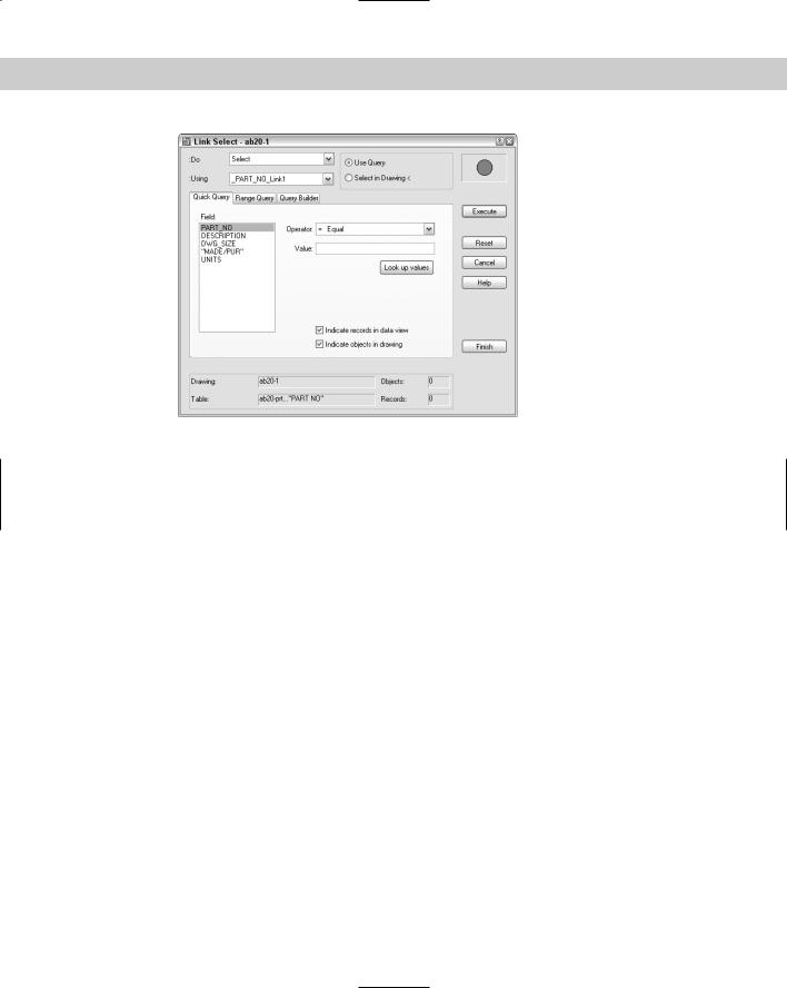
Figure 20-23: Use the Link Select dialog box to create combined selection sets of objects from queries and/or direct selection in your drawing.
3.Click Execute to add the query or selection of objects in your drawing to the Link Select operation.
4.Create a second selection set using the same process.
5.From the Do drop-down list, choose one of the logical operators. You now have one selection set from the combined selection sets you specified.
6.If you want, you can now create an additional selection set and use an operator to combine it with the previous selection set created in Step 5.
7.Choose Finish to complete the process.
Working with Query Files
You can store, edit, rename, and delete queries. You can also import and export them for use by others. To use ASE links created in Releases 13 and 14, you need to convert them to AutoCAD 2005 format.
Storing queries
As I discussed previously, you can store a query by clicking Store on any tab. Stored queries are displayed under the drawing in the dbConnect window. To execute a stored query, choose dbConnect Queries Execute Query. Choose the query you want to execute and click OK. It helps if the queries have names that meaningfully relate to the query.
You can also edit a query. Choose dbConnect Queries Edit Query. Choose the query and click Continue. In the Query Editor, make the desired changes and choose Store.

Chapter 20 Working with External Databases |
589 |
To rename a query, click it in the dbConnect window. Click it again to display an edit box. You can now edit the query’s name. Remember that you have to name the query up front. If you’re not sure what the query will consist of, use the default name, construct your query, and then rename it to something more meaningful afterward.
To delete a query, choose dbConnect Queries Delete Query. Choose the query or queries and click OK.
Importing and exporting queries
To export a query that has been saved (by clicking Store in the Query Editor), choose dbConnect Queries Export Query Set. In the Export Query Set dialog box, navigate to the desired folder and choose a name. Click Save. Queries have a .dbq filename extension.
Note |
To find the location of your queries, choose Tools Options and click the Files tab. Double- |
|
click Data Sources Location to see the path. |
To import a query that has been exported and named, choose dbConnect Queries Import Query Set. You need to know the name and location of the .dbq file. In the Import Query Set dialog box, locate the file and click Open. If your drawing already contains a query with the same name, AutoCAD adds a number to the name of the query so it has a unique name. This can easily occur because AutoCAD assigns default names to queries.
Summary
Using external databases to store data about drawing objects can reduce the size of drawings, simplify reporting, make data accessible to all users on a network, and enable you to edit a database from inside AutoCAD. In this chapter you read about:
Configuring a data source
Connecting a database table with your drawing
Creating a link template
Creating links between drawing objects and rows in the database
Creating labels containing information from the database
Defining SQL queries to select and sort the data you view
Selecting objects based on queries
Storing and saving queries
Converting links from Releases 12 through 14.
This chapter ends Part III, “Working with Data.” In Part IV, you start to draw in three dimensions. In the next chapter, I discuss how to specify 3D coordinates.
|
|
|

Drawing in Three
Dimensions
Part IV introduces you to three-dimensional drawing. AutoCAD creates three types of 3D objects, also called models — wireframes, surfaces, and solids. Wireframes, as the name implies, look like models created with wire. They don’t have real surfaces
or solidity. However, they’re useful for creating shapes that you can turn into surfaces or solids. Surfaces, unlike wireframes, can hide objects behind them. They’re especially useful for creating unusually shaped objects. Solids are defined as the entire volume of space they enclose. You can add and subtract solids from each other, creating realistic objects.
AutoCAD LT can only create wireframes and one kind of surface. AutoCAD LT’s 3D capabilities are quite limited, but you can still create simple 3D objects in AutoCAD LT. Furthermore, AutoCAD LT can open and display a drawing that contains 3D objects created in AutoCAD.
In Chapter 21, I explain the basics of 3D drawing, including specifying 3D coordinates, using the User Coordinate System for 3D drawing, and creating objects with elevation and thickness. Chapter 22 explains the techniques for viewing 3D objects. Chapter 23 covers surface models. Chapter 24 explains how to create true solids and covers editing in three dimensions. Chapter 25 explains how to create photorealistic views of your 3D drawings using AutoCAD’s rendering feature.
Note |
Chapters 23 through 25 apply to AutoCAD only. |
P A R T
IV
In This Part
Chapter 21
Specifying 3D
Coordinates
Chapter 22
Viewing 3D Drawings
Chapter 23
Creating 3D Surfaces
Chapter 24
Creating Solids
and Editing in 3D
Chapter 25
Rendering in 3D

Specifying 3D
Coordinates
Until now, you’ve worked with two axes, X and Y. When you work in three dimensions, you add the Z axis. After you have a drawing with 3D objects, you can view it from any angle. The view you’ve
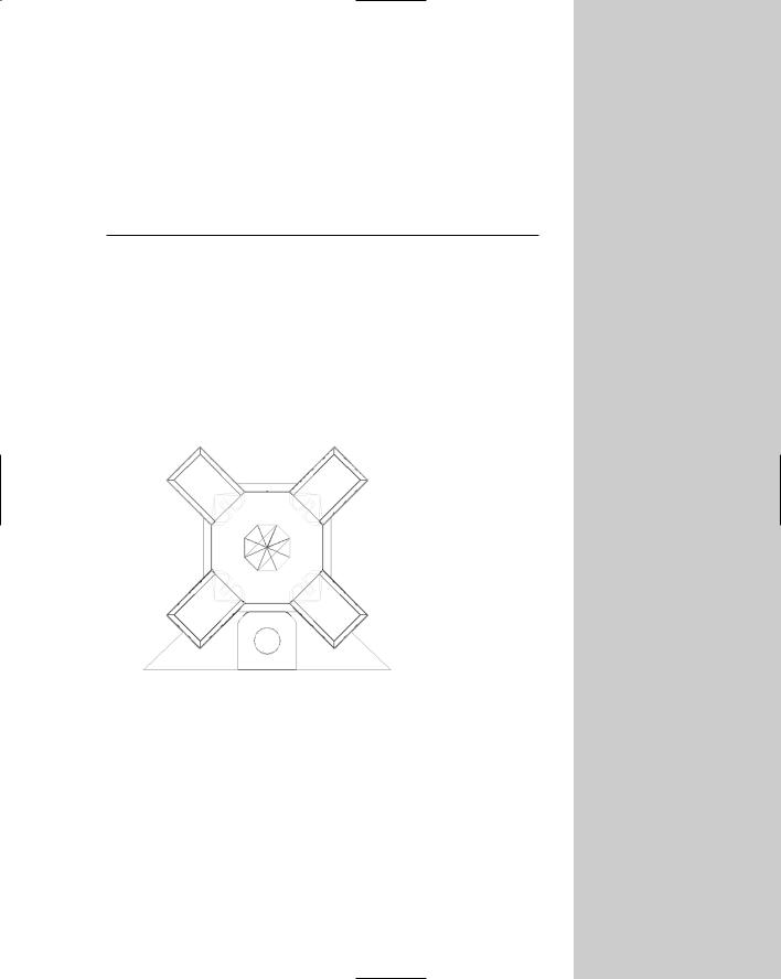
been using in 2D drawings is like looking at a house from the top, which you could call a plan view or a floor plan. From this view, even a 3D drawing looks two-dimensional. But when you look at a 3D drawing from an angle, you can see that there’s more to it than meets the eye. Figure 21-1 shows the plan view of an office building. Figure 21-2 shows the same drawing viewed in a perspective view from the front.
Figure 21-1: An office building in plan view.
Thanks to Roger Cusson of Interface Architectural
Software, Montreal, Quebec, for this drawing.
Although this drawing is quite complex, you can easily get started by working on simpler models. Three-dimensional drawing is not as difficult as it seems at first. In this chapter, I start by explaining how to work with 3D coordinates. I also cover wireframe models and 3D surfaces created with thickness and elevation. These are essentially 2D objects placed in 3D space and are, therefore, a good place to start when learning about drawing in 3D. Most of the features that I cover in this chapter apply to AutoCAD LT as well as AutoCAD.
21C H A P T E R
In This Chapter
Understanding 3D drawings
Working with 3D coordinates
Using point filters, object snaps, and grips in 3D
Using elevation and thickness
Creating a custom UCS for 3D drawings