

- •Foreword
- •Preface
- •Is This Book for You?
- •How This Book Is Organized
- •How to Use This Book
- •Doing the Exercises
- •Conventions Used in This Book
- •What the Icons Mean
- •About the CD-ROM
- •Other Information
- •Contacting the Author
- •Acknowledgments
- •Contents at a Glance
- •Contents
- •Getting Acquainted with AutoCAD and AutoCAD LT
- •Starting AutoCAD and AutoCAD LT
- •Creating a New Drawing
- •Using the AutoCAD and AutoCAD LT Interface
- •Creating Your First Drawing
- •Saving a Drawing
- •Summary
- •Creating a New Drawing from a Template
- •Working with Templates
- •Opening a Drawing with Default Settings
- •Opening an Existing Drawing
- •Using an Existing Drawing as a Prototype
- •Saving a Drawing Under a New Name
- •Summary
- •The Command Line
- •Command Techniques
- •Of Mice and Pucks
- •Getting Help
- •Summary
- •Typing Coordinates
- •Displaying Coordinates
- •Picking Coordinates on the Screen
- •Locating Points
- •Summary
- •Unit Types
- •Drawing Limits
- •Understanding Scales
- •Inserting a Title Block
- •Common Setup Options
- •The MVSETUP Command
- •Summary
- •Using the LINE Command
- •Drawing Rectangles
- •Drawing Polygons
- •Creating Construction Lines
- •Creating Rays
- •Summary
- •Drawing Circles
- •Drawing Arcs
- •Creating Ellipses and Elliptical Arcs
- •Making Donuts
- •Placing Points
- •Summary
- •Panning
- •The ZOOM Command
- •Aerial View
- •Named Views
- •Tiled Viewports
- •Snap Rotation
- •User Coordinate Systems
- •Isometric Drawing
- •Summary
- •Editing a Drawing
- •Selecting Objects
- •Summary
- •Copying and Moving Objects
- •Using Construction Commands
- •Creating a Revision Cloud
- •Hiding Objects with a Wipeout
- •Double-Clicking to Edit Objects
- •Grips
- •Editing with the Properties Palette
- •Selection Filters
- •Groups
- •Summary
- •Working with Layers
- •Changing Object Color, Linetype, and Lineweight
- •Working with Linetype Scales
- •Importing Layers and Linetypes from Other Drawings
- •Matching Properties
- •Summary
- •Drawing-Level Information
- •Object-Level Information
- •Measurement Commands
- •AutoCAD’s Calculator
- •Summary
- •Creating Single-Line Text
- •Understanding Text Styles
- •Creating Multiline Text
- •Creating Tables
- •Inserting Fields
- •Managing Text
- •Finding Text in Your Drawing
- •Checking Your Spelling
- •Summary
- •Working with Dimensions
- •Drawing Linear Dimensions
- •Drawing Aligned Dimensions
- •Creating Baseline and Continued Dimensions
- •Dimensioning Arcs and Circles
- •Dimensioning Angles
- •Creating Ordinate Dimensions
- •Drawing Leaders
- •Using Quick Dimension
- •Editing Dimensions
- •Summary
- •Understanding Dimension Styles
- •Defining a New Dimension Style
- •Changing Dimension Styles
- •Creating Geometric Tolerances
- •Summary
- •Creating and Editing Polylines
- •Drawing and Editing Splines
- •Creating Regions
- •Creating Boundaries
- •Creating Hatches
- •Creating and Editing Multilines
- •Creating Dlines
- •Using the SKETCH Command
- •Digitizing Drawings with the TABLET Command
- •Summary
- •Preparing a Drawing for Plotting or Printing
- •Creating a Layout in Paper Space
- •Working with Plot Styles
- •Plotting a Drawing
- •Summary
- •Combining Objects into Blocks
- •Inserting Blocks and Files into Drawings
- •Managing Blocks
- •Using Windows Features
- •Working with Attributes
- •Summary
- •Understanding External References
- •Editing an Xref within Your Drawing
- •Controlling Xref Display
- •Managing Xrefs
- •Summary
- •Preparing for Database Connectivity
- •Connecting to Your Database
- •Linking Data to Drawing Objects
- •Creating Labels
- •Querying with the Query Editor
- •Working with Query Files
- •Summary
- •Working with 3D Coordinates
- •Using Elevation and Thickness
- •Working with the User Coordinate System
- •Summary
- •Working with the Standard Viewpoints
- •Using DDVPOINT
- •Working with the Tripod and Compass
- •Getting a Quick Plan View
- •Shading Your Drawing
- •Using 3D Orbit
- •Using Tiled Viewports
- •Defining a Perspective View
- •Laying Out 3D Drawings
- •Summary
- •Drawing Surfaces with 3DFACE
- •Drawing Surfaces with PFACE
- •Creating Polygon Meshes with 3DMESH
- •Drawing Standard 3D Shapes
- •Drawing a Revolved Surface
- •Drawing an Extruded Surface
- •Drawing Ruled Surfaces
- •Drawing Edge Surfaces
- •Summary
- •Drawing Standard Shapes
- •Creating Extruded Solids
- •Drawing Revolved Solids
- •Creating Complex Solids
- •Sectioning and Slicing Solids
- •Using Editing Commands in 3D
- •Editing Solids
- •Listing Solid Properties
- •Summary
- •Understanding Rendering
- •Creating Lights
- •Creating Scenes
- •Working with Materials
- •Using Backgrounds
- •Doing the Final Render
- •Summary
- •Accessing Drawing Components with the DesignCenter
- •Accessing Drawing Content with Tool Palettes
- •Setting Standards for Drawings
- •Organizing Your Drawings
- •Working with Sheet Sets
- •Maintaining Security
- •Keeping Track of Referenced Files
- •Handling Errors and Crashes
- •Managing Drawings from Prior Releases
- •Summary
- •Importing and Exporting Other File Formats
- •Working with Raster Images
- •Pasting, Linking, and Embedding Objects
- •Summary
- •Sending Drawings
- •Opening Drawings from the Web
- •Creating Object Hyperlinks
- •Publishing Drawings
- •Summary
- •Working with Customizable Files
- •Creating Keyboard Shortcuts for Commands
- •Customizing Toolbars
- •Customizing Tool Palettes
- •Summary
- •Creating Macros with Script Files
- •Creating Slide Shows
- •Creating Slide Libraries
- •Summary
- •Creating Linetypes
- •Creating Hatch Patterns
- •Summary
- •Creating Shapes
- •Creating Fonts
- •Summary
- •Working with Menu Files
- •Customizing a Menu
- •Summary
- •Introducing Visual LISP
- •Getting Help in Visual LISP
- •Working with AutoLISP Expressions
- •Using AutoLISP on the Command Line
- •Creating AutoLISP Files
- •Summary
- •Creating Variables
- •Working with AutoCAD Commands
- •Working with Lists
- •Setting Conditions
- •Managing Drawing Objects
- •Getting Input from the User
- •Putting on the Finishing Touches
- •Summary
- •Understanding Local and Global Variables
- •Working with Visual LISP ActiveX Functions
- •Debugging Code
- •Summary
- •Starting to Work with VBA
- •Writing VBA Code
- •Getting User Input
- •Creating Dialog Boxes
- •Modifying Objects
- •Debugging and Trapping Errors
- •Moving to Advanced Programming
- •A Final Word
- •Installing AutoCAD and AutoCAD LT
- •Configuring AutoCAD
- •Starting AutoCAD Your Way
- •Configuring a Plotter
- •System Requirements
- •Using the CD with Microsoft Windows
- •What’s on the CD
- •Troubleshooting
- •Index
304 Part II Drawing in Two Dimensions
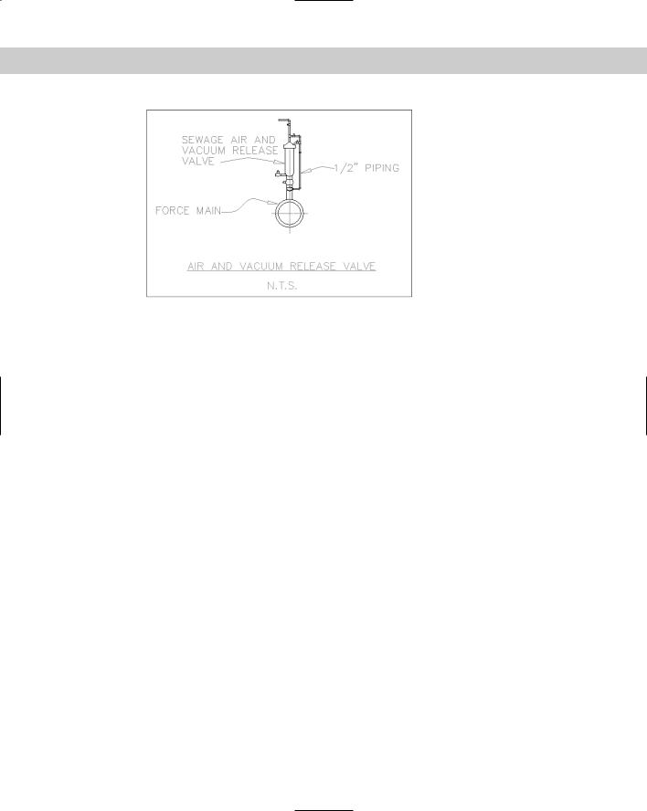
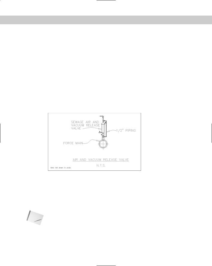
Figure 13-9: An air and vacuum release valve.
Thanks to the Army Corps of Engineers for this drawing.
5.Choose Layer. From the Layer drop-down list, choose TEXT. Choose Color. From the Color drop-down list, choose ByLayer. All text is now on the TEXT layer using the ByLayer color. Press Esc to remove the grips and see the result.
6.Select the text at the bottom of the drawing that reads N.T.S. From the grips you can tell
that it has a middle-left justification. Choose Modify Object Text Justify (or type justifytext on the command line). At the prompt, type bc .
The command ends. If you want, select the text again to see that the insertion point grip is now at the bottom-center of the text.
7.Choose Modify Object Text Scale (or type scaletext on the command line). Follow the prompts:
Select objects: Select the two lines of text at the bottom of the
drawing.
Select objects:
Enter a base point option for scaling
[Existing/Left/Center/Middle/Right/TL/TC/TR/ML/MC/MR/BL/BC/BR] <BC>:
Type e to use the existing base point.
Specify new height or [Match object/Scale factor] <1/8">: Right-click
and choose Scale factor.
Specify scale factor or [Reference] <2">: Type 1.5 .
8.If you want, click the Properties palette’s Close button to close it. Save your drawing.
Understanding Text Styles
You certainly do not always want to use the default font. You can create text styles that give you full creative control over the font, font style (bold, italic, or both), character width, obliquing angle, and text height. You can even design backward, upside-down, and vertical text. (Vertical text is like the text you occasionally see on the spine of a book. It goes down instead of to the right.)
Chapter 13 Creating Text 305
Text styles are similar to layers, which I discuss in Chapter 11. Like a layer, each text style:
Has a name and several properties
Is saved with the drawing
Can be made current when you want to use it
Can be renamed and deleted
Creating text styles is part of the typical drawing setup procedure. You should include text styles in your drawing templates. AutoCAD and AutoCAD LT come with two types of fonts — the original .shx fonts, which are created using shape files, and TrueType fonts — the fonts used by most Windows applications.
Cross- |
See Chapter 32 for instructions on creating shape files and your own fonts. |
Reference |
|
Creating a new text style
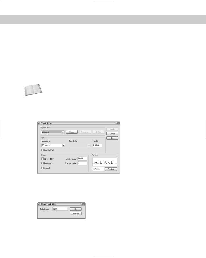
To create a new text style, choose Format Text Style. This starts the STYLE command and opens the Text Style dialog box, shown in Figure 13-10.
Figure 13-10: The Text Style dialog box.
Choose New to open the New Text Style dialog box, as shown in Figure 13-11. Type the name of your new text style and click OK. Text style names can be up to 255 characters and can include spaces. You return to the Text Style dialog box where you define the new text style.
Figure 13-11: The New Text Style dialog box.
306 Part II Drawing in Two Dimensions
Font
In the Font section of the Text Style dialog box, you specify the font, font style, and text height. Click the Font Name drop-down list arrow to see the list of fonts. Fonts with the double-T icon are TrueType fonts. The other fonts are fonts that are defined in a shape file that has the file name extension .shp and are compiled into a file with the extension .shx for faster access.
Click a font to choose it. You can see a preview of the font in the Preview section of the dialog box. The Preview section also has an edit box. Type some characters and click Preview to see the preview of those characters.
If the font you’ve chosen supports different styles, such as bold or italic, you can choose one of them in the Font Style drop-down box. None of the AutoCAD or AutoCAD LT fonts supports font styles, but many of the TrueType fonts do.
Type in the height you want for your font. Remember to take into account the scale factor if necessary.
You can leave the height at zero if you want to be able to vary the text height within that one style. If the height is zero, the DTEXT and TEXT commands prompt you for a height when you use these commands to place text.
Caution |
If you create a text style using a height other than zero and use that text style when you |
|
define a dimension style, the text style height overrides the text height that you specify sep- |
|
arately in the dimension style. See Chapter 15 for more information on dimension styles. |
Effects
In the Effects section, you specify the orientation, width factor, and oblique angle of the text style.
The default width of characters is set to 1. You can specify a smaller number to compress text and a larger number to expand it, as shown in Figure 13-12.
Width = 1.5
Width = .8
Figure 13-12: Text using different width factors.
The term oblique angle refers to the angle of the individual letters. It is generally used to create an effect, such as italic text. Of course, you don’t need to use an oblique angle if you’re using a TrueType font that supports italic text.
The angle definition used to define oblique text is different from the angle definition used for other objects. Up and down text — that is, normal text — is a zero oblique angle. A positive angle slants the text to the right — typical for italic text. A negative angle slants the text to the left. Figure 13-13 shows text with a positive and negative oblique angle.
Chapter 13 Creating Text 307
Oblique angle = –10
Oblique angle = 10
Figure 13-13: Text using differing oblique angles.
You can create text that is backward (like a mirror image) or upside-down. Some fonts let you create vertical text. Figure 13-14 shows an example of each kind of text. Check the appropriate check box to create the effect you want.
Figure 13-14: Vertical, backward, and upsidedown vertical text.
After you finish defining your text style, click Apply to make it current. Click Close to return to your drawing.
Renaming and deleting text styles
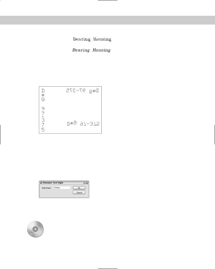
You can rename and delete text styles easily. To rename a text style, start the STYLE command to open the Text Style dialog box. Choose Rename to open the Rename Text Style dialog box, as shown in Figure 13-15. It works just like the New Text Style dialog box.
Figure 13-15: The Rename Text Style dialog box.
To delete a text style, choose it from the Style Name drop-down list of the Text Style dialog box and click Delete. A message box asks you to confirm. Click Yes to delete the text style. You cannot delete a text style that is being used.
On the |
The drawing used in the following Step-by-Step exercise on creating text styles, ab13-b.dwg, |
CD-ROM |
is in the Drawings folder on the CD-ROM. |
308 Part II Drawing in Two Dimensions
STEP-BY-STEP: Creating Text Styles
1.Open ab13-b.dwg from your CD-ROM.
2.Save the file as ab13-03.dwg in your AutoCAD Bible folder.
3.Choose Format Text Style to open the Text Style dialog box. Click New. In the New Text Style dialog box, type Notes and click OK.
4.From the Font Name drop-down list, choose romans.shx. In the Height text box, change the height to 1/16". In the Width Factor text box, change the width factor to .95. In the Oblique Angle text box, type 10. Click Apply to make the new style current. Click Close.
5.Start the DTEXT command. At the Specify start point of text or [Justify/ Style]: prompt, pick a start point at the lower-left corner of the drawing. At the
Specify rotation angle of text <0>: prompt, press Enter. At the Enter Text: prompt, type Note: Not drawn to scale. . Press Enter again to end the command.
6.Save your drawing. It should look like Figure 13-16. If you’re going on to the next exercise, keep this drawing open.
Figure 13-16: You’ve added text by using a new text style.
Modifying a text style
To change a style, choose Format Text Style. From the Style Name drop-down list, choose the text style you want to change. Make changes the same way you did when creating the style. Choose Apply and then Close. The drawing regenerates and the text that uses the style you changed is modified accordingly. This is a powerful way to control the look of text in your drawing.
Note |
Unfortunately, only changes to the font and text style affect current text. Other changes, such |
|
as width factor, oblique angle, orientation, and height, are ignored. However, new text takes |
|
on these other changes. |
Chapter 13 Creating Text 309
Making a style current or changing a text object’s style
You can choose the current style when you use one of the text commands. If you use DTEXT or TEXT, the command displays the Specify start point of text or [Justify/ Style]: prompt. Right-click and choose Style. (The prompt also displays the current style and height.) If you know the name of the style you want to use, type it and press Enter. The
Specify start point of text or [Justify/Style]: prompt repeats. You can choose the Justify option or pick a start point to continue the command.
If you use MTEXT, the Multiline Editor opens, as explained in the next section. Choose the text style you want from the Style drop-down list.
The Styles toolbar is an easy way to make a style current or change the text style of existing text. To make a style current, choose the style from the Text Style Control drop-down list with no text selected. To change the text style of existing text, select the text and choose a new style from the list. You can also change the style of selected text in the Properties palette.
Importing a text style
As explained in Chapter 11, you can use the DesignCenter to import features from other drawings. To import a text style, follow these steps:
1.Choose DesignCenter from the Standard toolbar to open the DesignCenter.
2.In the left pane, navigate to the drawing that has the text style you want.
3.Double-click the drawing icon or click its plus sign.
4.To see the list of the text styles, double-click the text style’s icon in either the left or right pane.
5.Double-click the text style’s icon to import it into your drawing.
6.Click the DesignCenter’s Close button to close the DesignCenter.
On the |
The drawing used in the following Step-by-Step exercise on changing text styles, ab13-3. |
CD-ROM |
dwg, is in the Results folder on the CD-ROM. |
STEP-BY-STEP: Modifying Text Styles
1.If you have ab13-03.dwg open from the previous Step-by-Step exercise, continue to use it for this exercise. Otherwise, open ab13-03.dwg from the Results folder of your CD-ROM.
2.Save the file as ab13-04.dwg in your AutoCAD Bible folder.
3.The note at the bottom-left corner of the drawing uses the Notes text style. Choose Format Text Style. In the Text Style dialog box, make sure NOTES is the style name listed, and then choose italic.shx from the Font Name drop-down list. Choose Apply and then Close.
4.The drawing regenerates and the text’s font changes.
5.Save your drawing.