

- •Foreword
- •Preface
- •Is This Book for You?
- •How This Book Is Organized
- •How to Use This Book
- •Doing the Exercises
- •Conventions Used in This Book
- •What the Icons Mean
- •About the CD-ROM
- •Other Information
- •Contacting the Author
- •Acknowledgments
- •Contents at a Glance
- •Contents
- •Getting Acquainted with AutoCAD and AutoCAD LT
- •Starting AutoCAD and AutoCAD LT
- •Creating a New Drawing
- •Using the AutoCAD and AutoCAD LT Interface
- •Creating Your First Drawing
- •Saving a Drawing
- •Summary
- •Creating a New Drawing from a Template
- •Working with Templates
- •Opening a Drawing with Default Settings
- •Opening an Existing Drawing
- •Using an Existing Drawing as a Prototype
- •Saving a Drawing Under a New Name
- •Summary
- •The Command Line
- •Command Techniques
- •Of Mice and Pucks
- •Getting Help
- •Summary
- •Typing Coordinates
- •Displaying Coordinates
- •Picking Coordinates on the Screen
- •Locating Points
- •Summary
- •Unit Types
- •Drawing Limits
- •Understanding Scales
- •Inserting a Title Block
- •Common Setup Options
- •The MVSETUP Command
- •Summary
- •Using the LINE Command
- •Drawing Rectangles
- •Drawing Polygons
- •Creating Construction Lines
- •Creating Rays
- •Summary
- •Drawing Circles
- •Drawing Arcs
- •Creating Ellipses and Elliptical Arcs
- •Making Donuts
- •Placing Points
- •Summary
- •Panning
- •The ZOOM Command
- •Aerial View
- •Named Views
- •Tiled Viewports
- •Snap Rotation
- •User Coordinate Systems
- •Isometric Drawing
- •Summary
- •Editing a Drawing
- •Selecting Objects
- •Summary
- •Copying and Moving Objects
- •Using Construction Commands
- •Creating a Revision Cloud
- •Hiding Objects with a Wipeout
- •Double-Clicking to Edit Objects
- •Grips
- •Editing with the Properties Palette
- •Selection Filters
- •Groups
- •Summary
- •Working with Layers
- •Changing Object Color, Linetype, and Lineweight
- •Working with Linetype Scales
- •Importing Layers and Linetypes from Other Drawings
- •Matching Properties
- •Summary
- •Drawing-Level Information
- •Object-Level Information
- •Measurement Commands
- •AutoCAD’s Calculator
- •Summary
- •Creating Single-Line Text
- •Understanding Text Styles
- •Creating Multiline Text
- •Creating Tables
- •Inserting Fields
- •Managing Text
- •Finding Text in Your Drawing
- •Checking Your Spelling
- •Summary
- •Working with Dimensions
- •Drawing Linear Dimensions
- •Drawing Aligned Dimensions
- •Creating Baseline and Continued Dimensions
- •Dimensioning Arcs and Circles
- •Dimensioning Angles
- •Creating Ordinate Dimensions
- •Drawing Leaders
- •Using Quick Dimension
- •Editing Dimensions
- •Summary
- •Understanding Dimension Styles
- •Defining a New Dimension Style
- •Changing Dimension Styles
- •Creating Geometric Tolerances
- •Summary
- •Creating and Editing Polylines
- •Drawing and Editing Splines
- •Creating Regions
- •Creating Boundaries
- •Creating Hatches
- •Creating and Editing Multilines
- •Creating Dlines
- •Using the SKETCH Command
- •Digitizing Drawings with the TABLET Command
- •Summary
- •Preparing a Drawing for Plotting or Printing
- •Creating a Layout in Paper Space
- •Working with Plot Styles
- •Plotting a Drawing
- •Summary
- •Combining Objects into Blocks
- •Inserting Blocks and Files into Drawings
- •Managing Blocks
- •Using Windows Features
- •Working with Attributes
- •Summary
- •Understanding External References
- •Editing an Xref within Your Drawing
- •Controlling Xref Display
- •Managing Xrefs
- •Summary
- •Preparing for Database Connectivity
- •Connecting to Your Database
- •Linking Data to Drawing Objects
- •Creating Labels
- •Querying with the Query Editor
- •Working with Query Files
- •Summary
- •Working with 3D Coordinates
- •Using Elevation and Thickness
- •Working with the User Coordinate System
- •Summary
- •Working with the Standard Viewpoints
- •Using DDVPOINT
- •Working with the Tripod and Compass
- •Getting a Quick Plan View
- •Shading Your Drawing
- •Using 3D Orbit
- •Using Tiled Viewports
- •Defining a Perspective View
- •Laying Out 3D Drawings
- •Summary
- •Drawing Surfaces with 3DFACE
- •Drawing Surfaces with PFACE
- •Creating Polygon Meshes with 3DMESH
- •Drawing Standard 3D Shapes
- •Drawing a Revolved Surface
- •Drawing an Extruded Surface
- •Drawing Ruled Surfaces
- •Drawing Edge Surfaces
- •Summary
- •Drawing Standard Shapes
- •Creating Extruded Solids
- •Drawing Revolved Solids
- •Creating Complex Solids
- •Sectioning and Slicing Solids
- •Using Editing Commands in 3D
- •Editing Solids
- •Listing Solid Properties
- •Summary
- •Understanding Rendering
- •Creating Lights
- •Creating Scenes
- •Working with Materials
- •Using Backgrounds
- •Doing the Final Render
- •Summary
- •Accessing Drawing Components with the DesignCenter
- •Accessing Drawing Content with Tool Palettes
- •Setting Standards for Drawings
- •Organizing Your Drawings
- •Working with Sheet Sets
- •Maintaining Security
- •Keeping Track of Referenced Files
- •Handling Errors and Crashes
- •Managing Drawings from Prior Releases
- •Summary
- •Importing and Exporting Other File Formats
- •Working with Raster Images
- •Pasting, Linking, and Embedding Objects
- •Summary
- •Sending Drawings
- •Opening Drawings from the Web
- •Creating Object Hyperlinks
- •Publishing Drawings
- •Summary
- •Working with Customizable Files
- •Creating Keyboard Shortcuts for Commands
- •Customizing Toolbars
- •Customizing Tool Palettes
- •Summary
- •Creating Macros with Script Files
- •Creating Slide Shows
- •Creating Slide Libraries
- •Summary
- •Creating Linetypes
- •Creating Hatch Patterns
- •Summary
- •Creating Shapes
- •Creating Fonts
- •Summary
- •Working with Menu Files
- •Customizing a Menu
- •Summary
- •Introducing Visual LISP
- •Getting Help in Visual LISP
- •Working with AutoLISP Expressions
- •Using AutoLISP on the Command Line
- •Creating AutoLISP Files
- •Summary
- •Creating Variables
- •Working with AutoCAD Commands
- •Working with Lists
- •Setting Conditions
- •Managing Drawing Objects
- •Getting Input from the User
- •Putting on the Finishing Touches
- •Summary
- •Understanding Local and Global Variables
- •Working with Visual LISP ActiveX Functions
- •Debugging Code
- •Summary
- •Starting to Work with VBA
- •Writing VBA Code
- •Getting User Input
- •Creating Dialog Boxes
- •Modifying Objects
- •Debugging and Trapping Errors
- •Moving to Advanced Programming
- •A Final Word
- •Installing AutoCAD and AutoCAD LT
- •Configuring AutoCAD
- •Starting AutoCAD Your Way
- •Configuring a Plotter
- •System Requirements
- •Using the CD with Microsoft Windows
- •What’s on the CD
- •Troubleshooting
- •Index

Chapter 23 Creating 3D Surfaces 669
Creating Polygon Meshes with 3DMESH
The 3DMESH command creates polygon meshes (not to be confused with the polyface meshes created by PFACE). The 3DMESH command is used for creating irregular surfaces, vertex by vertex. The great advantage of polygon meshes is that AutoCAD considers them to be polylines, and they can therefore be edited with the PEDIT command — although in a limited manner. Figure 23-10 shows two surfaces created with 3DMESH. The surface on the right has been smoothed using PEDIT.
Figure 23-10: Two surfaces created with 3DMESH. The surface on the right has been smoothed using the Smooth option of PEDIT.
To use 3DMESH, choose 3D Mesh from the Surfaces toolbar. AutoCAD then asks you for the Mesh M size and Mesh N size. M is the number of vertices going in the first direc-
tion. N is the number of vertices going in the other direction. Figure 23-11 shows a 3D Mesh with an M size of 5 and an N size of 3.
|
|
(1,2) |
(3,2) |
|
|
||
|
|
(2,2) |
|
|
|
||
|
(0,2) |
|
|
|
|
|
|
|
|
|
|
|
|
|
|
|
3 |
|
|
|
(3,1) |
|
(4,2) |
N=3 |
(0,1) |
(1,1) |
|
|
|
(4,1) |
|
|
(2,1) |
|
|
||||
|
|
|
|
||||
|
2 |
|
|
|
|
|
|
Vertex (0,0) |
(1,0) |
|
|
|
|
|
|
|
1 |
(2,0) |
(3,0) |
|
(4,0) |
||
|
2 |
|
|||||
|
|
|
3 |
|
4 |
5 |
|
|
|
|
|
|
|||
M=5
Figure 23-11: A 3D Mesh with an M size of 5 and an N size of 3, showing the vertex designations.
After you set the size of the 3D Mesh, you need to specify each vertex. For example, the 3D Mesh in Figure 23-11 has 15 vertices that you need to specify. AutoCAD prompts you for each vertex in order, starting with (0,0). Vertex (0,1) is the second vertex in the first column. Vertex (1,0) is the first vertex in the second column, starting from the bottom. It’s a little confusing because AutoCAD starts the counting from 0 (zero), not 1. For the 3D Mesh in Figure 23-11, the last vertex is (4,2).
670 Part IV Drawing in Three Dimensions
Note |
In Figure 23-11, the 3D Mesh is five vertices wide and three vertices high as you look at it in |
|
plan view. However, you don’t have to specify the vertices in the same direction. For the 3D |
|
mesh in the figure, I started at the bottom left, continued to move up for (0,1) and (0,2), |
|
then moved to the right. However, you could start at the bottom-left and move to the right |
|
for (0,1) and (0,2), and then go back to the left either above or below (0,0) — resulting in a |
|
3D mesh that is three vertices wide and five vertices high as you look at it in plan view. In |
|
other words, M and N can be in any direction. |
|
3D meshes are especially suitable for AutoLISP routines; in fact, AutoCAD supplies several. |
|
These are discussed in the next section. |
|
To smooth a polygon mesh, start the PEDIT command and select the polygon mesh. AutoCAD |
|
responds with the Enter an option [Edit vertex/Smooth surface/Desmooth/Mclose/ |
|
Nclose/Undo]: prompt. Table 23-1 explains how to use these options. |
|
Table 23-1: PEDIT Options for 3D Polygon Meshes |
|
|
Option |
Description |
|
|
Edit vertex |
Displays the Current vertex (0,0). Enter an option -[Next/ |
|
Previous/Left/Right/Up/Down/Move/REgen/eXit] <N>: prompt. Use the |
|
Next, Previous, Left, Right, Up, and Down suboptions to move the X marker that |
|
displays the current vertex. When you’re at the vertex you want to move, use the |
|
Move suboption. REgen regenerates the 3D mesh. Use eXit to return to the original |
|
prompt. |
Smooth surface |
Smoothes the surface according to one of three possible sets of equations — |
|
Quadratic, Cubic, or Bézier. Bézier results in the smoothest surface. Use the |
|
SURFTYPE system variable to set the type of smoothing. Set SURFTYPE to 5 to |
|
create a quadratic b-spline surface, 6 to create a cubic b-spline surface, or 7 to |
|
create a Bézier surface. Cubic (6) is the default setting. To smooth a 3D Mesh, there |
|
must be more than three vertices in both the M and N directions. |
Desmooth |
Removes the smoothing on the 3D mesh surface. |
Mclose |
Closes the surface in the M direction by connecting the last edge to the first edge. |
Nclose |
Closes the surface in the N direction by connecting the last edge to the first edge. |
Undo |
Undoes the last option. |
|
|
You can use 3DMESH to create 3D topological surfaces. You may have a surveyor’s drawing marking measurement points. Open a new drawing, using the surveyor’s drawing as an xref. In plan view, create a polygon mesh. For the vertices, pick the surveyor’s measurement points. (You’ll need to count them first to determine a regular grid for the M and N sizes.) Then select the polygon mesh to display its grip points. Select each grip in turn, and at the prompt, type (for example) @0,0,100.78 where the last coordinate is the measured height. When you’re done, look at the surface in any nonplanar viewpoint to see the result.
Chapter 23 Creating 3D Surfaces 671
Drawing Standard 3D Shapes
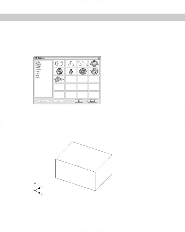
AutoCAD includes several AutoLISP routines that use the 3DMESH command to create some standard shapes. These shapes all have icons on the Surfaces toolbar. You can also choose Draw Surfaces 3D Surfaces to open the 3D Objects dialog box, as shown in Figure 23-12.
Figure 23-12: The 3D Objects dialog box.
On the command line, you can type 3d and choose the shape you want to draw from the command options. You can also type ai_ followed by the name of the shape, such as ai_box.
Box
Figure 23-13 shows a box from the SE isometric viewpoint after using the HIDE command.
Figure 23-13: A box from an isometric viewpoint after using the HIDE command.

672 Part IV Drawing in Three Dimensions
Here’s how to draw a box:
1. Choose Box from the Surfaces toolbar.
2.At the Specify corner point of box: prompt, specify the lower-left corner of the base of the box.
3. At the Specify length of box: prompt, specify the length of the box along the
X axis.
4.At the Specify width of box or [Cube]: prompt, specify the width of the box along the Y axis. If you choose the Cube option, AutoCAD creates a cube with a width and height the same as the length you just specified, and you don’t see the height prompt.
5. At the Specify height of box: prompt, specify the height of the box along the
Z axis.
6.At the Specify rotation angle of box about the Z axis or [Reference]:
prompt, specify an angle. AutoCAD rotates the box in the XY plane. There is no default of 0 (zero) degrees, so you must type 0 even if you do not want to rotate the box. You can also use the Reference suboption, which works like the Reference option of the ROTATE command.
As you define the box, AutoCAD draws a temporary image in yellow to show you the result of your specifications.
Wedge
Figure 23-14 shows a wedge. The prompts are the same as for the box, except that there is no Cube option. A wedge is half of a box.
Figure 23-14: A wedge from an isometric viewpoint after the HIDE command.
Chapter 23 Creating 3D Surfaces 673
Here’s how to draw a wedge:
1. Choose Wedge from the Surfaces toolbar.
2.At the Specify corner point of wedge: prompt, specify the lower-left corner of the base of the wedge.
3. |
At the Specify length of wedge: prompt, specify the length of the wedge along the |
|
X axis. |
4. |
At the Specify width of wedge: prompt, specify the width of the wedge along the |
|
Y axis. |
5. |
At the Specify height of wedge: prompt, specify the height of the wedge along the |
|
Z axis. |
6. |
At the Specify rotation angle of wedge about the Z axis: prompt, specify |
|
an angle. AutoCAD rotates the wedge in the XY plane. There is no default of 0 (zero) |
|
degrees, so you must type 0 even if you don’t want to rotate the wedge. |
Pyramid
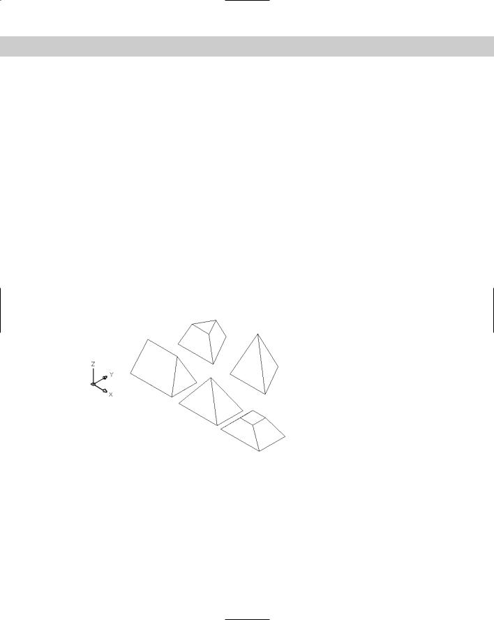
You can draw pyramids with threeand four-sided bases. A pyramid with a three-sided base creates a four-sided object called a tetrahedron. You can top the pyramid with a point, a flat top or, for four-sided bases, a ridge. Figure 23-15 shows the various types of pyramids you can draw.
Figure 23-15: You can draw all these pyramidal shapes.
Here’s how to draw the pyramids:
1. Choose Pyramid from the Surfaces toolbar.
2.At the Specify first corner point for base of pyramid: prompt, specify the first point (any point) on the base.
3.At the Specify second corner point for base of pyramid: prompt, specify the second point on the base.
674 Part IV Drawing in Three Dimensions
4.At the Specify third corner point for base of pyramid: prompt, specify the third point on the base.
5.At the Specify fourth corner point for base of pyramid or [Tetrahedron]: prompt, specify the fourth point on the base or choose the Tetrahedron option (creates a pyramid with a base of three points).
•If you chose the Tetrahedron option, at the Specify apex point of tetrahedron or [Top]: prompt specify the apex (top point) or choose the Top option. AutoCAD prompts you for three top points.
•If you specified a fourth base point, at the Specify apex point of pyramid or [Ridge/Top]: prompt specify the apex (top point) or choose the Ridge or Top options. If you choose the Ridge option, specify the two points for the ridge. If you choose the Top option, specify the four top points.
Specifying the apex or ridge can be tricky unless you know the absolute coordinates you want. You can’t change viewpoints during the command. However, you can easily change the points later using grips. Another trick is to start any drawing command, such as LINE, before starting the pyramid. At the Specify first point: prompt, pick the point you want to use for the first base point of the pyramid. Then press Esc to cancel the command. This leaves that point as the last point specified. Now define the base of the pyramid, using the same point as the first base point. When you need to specify the apex or ridge, you can use relative coordinates from the first base point. For example, to create an apex two units directly over the first base point, specify @0,0,2 for the apex. When you use the Top option, AutoCAD provides a rubber-band line from each of the base corners in turn, letting you use relative coordinates from the base corners. You can also create a temporary 2D object before starting the pyramid to frame a ridge or top.
Cone
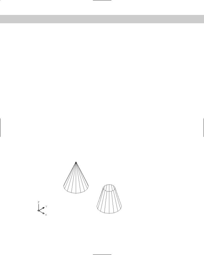
You can create full or partial cones. Figure 23-16 shows both types, as displayed after using the HIDE command.
Figure 23-16: You can draw full or partial cones.
Chapter 23 Creating 3D Surfaces 675
Follow these steps to create cones:
1. Choose Cone from the Surfaces toolbar.
2.At the Specify center point for base of cone: prompt, pick the center for the circle that makes the base of the cone.
3.At the Specify radius for base of cone or [Diameter]: prompt, specify the radius for the circle at the base or choose the Diameter option to specify the diameter.
4.At the Specify radius for top of cone or [Diameter] <0>: prompt, specify the radius of the top or choose the Diameter option and specify the diameter. If you accept the default of zero, you get a complete cone. If you specify a radius or diameter, you get a truncated cone.
Note You can specify the base’s size to be larger than the top’s size, resulting in an inverted cone.
5. |
At the Specify height of cone: prompt, specify the height. |
6. |
At the Enter number of segments for surface of cone <16>: prompt, specify |
|
the number of mesh segments. A higher number results in a smoother-looking cone. |
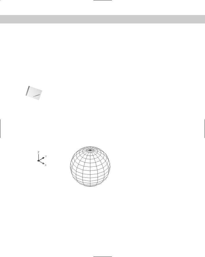
Sphere
Drawing a sphere is quite easy — you just specify the center and radius, and then the number of segments to display in each direction. Figure 23-17 shows a sphere after using the HIDE command.
Figure 23-17: A sphere.
Here’s how to draw a sphere:
1. Choose Sphere from the Surfaces toolbar.
2.At the Specify center point of sphere: prompt, specify a point.
3.At the Specify radius of sphere or [Diameter]: prompt, specify the radius, or choose the Diameter option to specify the diameter.

676 Part IV Drawing in Three Dimensions
4.At the Enter number of longitudinal segments for surface of sphere <16>: prompt, type the number of north-south lines you want. A higher number results in a smoother-looking sphere.
5.At the Enter number of latitudinal segments for surface of sphere <16>: prompt, type the number of east-west lines you want. A higher number results in a smoother-looking sphere.
The only tricky point with spheres is remembering that the center point is the center in all three dimensions. If you want to draw a ball on a table, it’s easy to specify the center on the plane of the tabletop — but you end up with a ball that’s half beneath the table. So plan ahead.
Dome
A dome is the top half of a sphere, as shown in Figure 23-18. The prompts are very similar to those for a sphere.
Figure 23-18: A dome.
Follow these steps to draw a dome:
1. Choose Dome from the Surfaces toolbar.
2.At the Specify center point of dome: prompt, specify the center point of the circle that makes up the base of the dome.
3.At the Specify radius of dome or [Diameter]: prompt, specify the radius or use the Diameter option to specify the diameter.
4.At the Enter number of longitudinal segments for surface of dome <16>: prompt, type the number of north-south lines you want. A higher number results in a smoother-looking dome.
5.At the Enter number of latitudinal segments for surface of dome <8>: prompt, type the number of east-west lines you want. A higher number results in a smoother-looking dome. Notice that the default is 8 instead of 16 for the sphere because you’re drawing only half a sphere.

Chapter 23 Creating 3D Surfaces 677
Dish
A dish is the bottom half of a sphere, as shown in Figure 23-19. Actually, a bowl would be a better name for it.
Figure 23-19: A dish.
Follow these steps to draw a dish:
1. Choose Dish from the Surfaces toolbar.
2.At the Specify center point of dish: prompt, specify the center point of the circle that makes up the base of the dish.
3.At the Specify radius of dish or [Diameter]: prompt, specify the radius or use the Diameter option to specify the diameter.
4.At the Enter number of longitudinal segments for surface of dish <16>: prompt, type the number of north-south lines you want. A higher number results in a smoother looking dish.
5.At the Enter number of latitudinal segments for surface of dome <8>: prompt, type the number of east-west lines you want. A higher number results in a smoother-looking dish. As with the dish, the default is 8 because you’re drawing only half a sphere.
As with spheres, remember that the center point is the center of the top of the dish, not its base.
Torus
A torus is a 3D donut, as shown in Figure 23-20.
Follow these steps to create a torus:
1. Choose Torus from the Surfaces toolbar.
2.At the Specify center point of torus: prompt, specify the center of the torus.

678 Part IV Drawing in Three Dimensions
3.At the Specify radius of torus or [Diameter]: prompt, specify the radius of the torus, as shown in Figure 23-20 or use the Diameter option to define the diameter.
4.At the Specify radius of tube or [Diameter]: prompt, specify the radius of the tube, as shown in Figure 23-20, or use the Diameter option to define the diameter.
5.At the Enter number of segments around tube circumference <16>: prompt, specify the number of segments around the tube, as shown in Figure 23-20.
6.At the Enter number of segments around torus circumference <16>: prompt, specify the number of segments around the torus, as shown in Figure 23-20.
Segments around torus circumference
Radius of torus
Radius of tube
Segments around tube circumference
Figure 23-20: A torus.
As with a sphere, a torus is half above and half below the center point in the Z direction.
Mesh
The 3D command has a Mesh option that does not appear on the Surfaces toolbar, but you can type 3d and choose the Mesh option or choose it from the 3D Objects dialog box. (Choose Draw Surfaces 3D Surfaces.)
The Mesh option creates a 3D mesh. All you have to do is pick the four corners and the M and N mesh sizes. Of course, this option doesn’t give you the flexibility of the 3DMESH command, but it’s a lot easier!
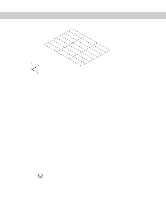
Specify the four corner points in clockwise or counterclockwise order. Then specify the M and N mesh sizes. Figure 23-21 shows a mesh with M=8 and N=4.
On the |
The drawing used in the following Step-by-Step exercise on drawing 3D polygon meshes, |
CD-ROM |
ab23-c.dwg, is in the Drawings folder on the CD-ROM. |
Chapter 23 Creating 3D Surfaces 679
Figure 23-21: A mesh with M=8 and N=4.
STEP-BY-STEP: Drawing 3D Polygon Meshes
1.Open ab23-c.dwg from the CD-ROM.
2.Save it as ab23-03.dwg in your AutoCAD Bible folder. The drawing is in architectural units. OSNAP should be on. Set running object snaps for endpoint and midpoint. If the Surfaces toolbar isn’t displayed, right-click any toolbar and choose Surfaces.
3. Choose Box from the Surfaces toolbar. Follow the prompts to make the tabletop:
Specify corner point of box: 1,1,30 Specify length of box: 4'
Specify width of box or [Cube]: 3' Specify height of box: 1
Specify rotation angle of box about the Z axis or [Reference]: 0
4.Do a Zoom Extents to see the entire box. You’re in plan view, so it looks like a rectangle.
5.Choose Box from the Surfaces toolbar again. Follow the prompts to make a leg:
Specify corner point of box: 1,1 Specify length of box: 1
Specify width of box or [Cube]: 1 Specify height of box: 30
Specify rotation angle of box about the Z axis or [Reference]: 0
6.Mirror the leg, which appears as a small square at the lower-left corner of the large rectangle, from the midpoint of one side of the table to the midpoint of the opposite side. Then mirror the two legs in the other direction (from the other two midpoints) so that you have four legs.
7.Choose Dish from the Surfaces toolbar. Follow the prompts to create a bowl on the table:
Specify center point of dish: 2',2',35-1/2 Specify radius of dish or [Diameter]: d
680 Part IV Drawing in Three Dimensions
Specify diameter of dish: 9
Enter number of longitudinal segments for surface of dish <16>: Enter number of latitudinal segments for surface of dish <8>:
The dish’s diameter is 9, so its height is half that, or 41⁄2. The center of the dish is at height 351⁄2 because the tabletop is at 31 (31 + 41⁄2 = 351⁄2).
8.Type elev . Change the elevation to 31. Leave the thickness at 0 (zero).
9.Choose Cone from the Surfaces toolbar. Follow the prompts to create a salt shaker:
Specify center point for base of cone: 2',1'6
Specify radius for base of cone or [Diameter]: 1
Specify radius for top of cone or [Diameter] <0>: .5
Specify height of cone: 4
Enter number of segments for surface of cone <16>: 8
10.Choose Sphere from the Surfaces toolbar. Follow the prompts to draw an orange in the bowl:
Specify center point of sphere: 2',2',32-1/2 Specify radius of sphere or [Diameter]: d Specify diameter of sphere: 3
Enter number of longitudinal segments for surface of sphere <16>: 8 Enter number of latitudinal segments for surface of sphere <16>: 8
11.Choose Cone from the Surfaces toolbar. Follow the prompts to make a plate.
(It may not seem logical to use a cone to make a flat plate. It works because you can create a truncated cone upside down and very shallow. It’s an unusual but interesting use for the CONE command.)
Specify center point for base of cone: 1',1' Specify radius for base of cone or [Diameter]: 2 Specify radius for top of cone or [Diameter] <0>: 5 Specify height of cone: 1/2
Enter number of segments for surface of cone <16>:
12.Choose View 3D Views SE Isometric to get a view of what you have already drawn.
13.Choose Wedge from the Surfaces toolbar. Follow the prompts to make a wedge of cheese on the plate:
Specify corner point of wedge: 10,10
Specify length of wedge: 5
Specify width of wedge: 2
Specify height of wedge: 2
Specify rotation angle of wedge about the Z axis: 30
14.Choose Pyramid from the Surfaces toolbar. Follow the prompts to draw a pyramidal pepper shaker:
Specify first corner point for base of pyramid: 2'6,2'6 Specify second corner point for base of pyramid: @1,0