

- •Foreword
- •Preface
- •Is This Book for You?
- •How This Book Is Organized
- •How to Use This Book
- •Doing the Exercises
- •Conventions Used in This Book
- •What the Icons Mean
- •About the CD-ROM
- •Other Information
- •Contacting the Author
- •Acknowledgments
- •Contents at a Glance
- •Contents
- •Getting Acquainted with AutoCAD and AutoCAD LT
- •Starting AutoCAD and AutoCAD LT
- •Creating a New Drawing
- •Using the AutoCAD and AutoCAD LT Interface
- •Creating Your First Drawing
- •Saving a Drawing
- •Summary
- •Creating a New Drawing from a Template
- •Working with Templates
- •Opening a Drawing with Default Settings
- •Opening an Existing Drawing
- •Using an Existing Drawing as a Prototype
- •Saving a Drawing Under a New Name
- •Summary
- •The Command Line
- •Command Techniques
- •Of Mice and Pucks
- •Getting Help
- •Summary
- •Typing Coordinates
- •Displaying Coordinates
- •Picking Coordinates on the Screen
- •Locating Points
- •Summary
- •Unit Types
- •Drawing Limits
- •Understanding Scales
- •Inserting a Title Block
- •Common Setup Options
- •The MVSETUP Command
- •Summary
- •Using the LINE Command
- •Drawing Rectangles
- •Drawing Polygons
- •Creating Construction Lines
- •Creating Rays
- •Summary
- •Drawing Circles
- •Drawing Arcs
- •Creating Ellipses and Elliptical Arcs
- •Making Donuts
- •Placing Points
- •Summary
- •Panning
- •The ZOOM Command
- •Aerial View
- •Named Views
- •Tiled Viewports
- •Snap Rotation
- •User Coordinate Systems
- •Isometric Drawing
- •Summary
- •Editing a Drawing
- •Selecting Objects
- •Summary
- •Copying and Moving Objects
- •Using Construction Commands
- •Creating a Revision Cloud
- •Hiding Objects with a Wipeout
- •Double-Clicking to Edit Objects
- •Grips
- •Editing with the Properties Palette
- •Selection Filters
- •Groups
- •Summary
- •Working with Layers
- •Changing Object Color, Linetype, and Lineweight
- •Working with Linetype Scales
- •Importing Layers and Linetypes from Other Drawings
- •Matching Properties
- •Summary
- •Drawing-Level Information
- •Object-Level Information
- •Measurement Commands
- •AutoCAD’s Calculator
- •Summary
- •Creating Single-Line Text
- •Understanding Text Styles
- •Creating Multiline Text
- •Creating Tables
- •Inserting Fields
- •Managing Text
- •Finding Text in Your Drawing
- •Checking Your Spelling
- •Summary
- •Working with Dimensions
- •Drawing Linear Dimensions
- •Drawing Aligned Dimensions
- •Creating Baseline and Continued Dimensions
- •Dimensioning Arcs and Circles
- •Dimensioning Angles
- •Creating Ordinate Dimensions
- •Drawing Leaders
- •Using Quick Dimension
- •Editing Dimensions
- •Summary
- •Understanding Dimension Styles
- •Defining a New Dimension Style
- •Changing Dimension Styles
- •Creating Geometric Tolerances
- •Summary
- •Creating and Editing Polylines
- •Drawing and Editing Splines
- •Creating Regions
- •Creating Boundaries
- •Creating Hatches
- •Creating and Editing Multilines
- •Creating Dlines
- •Using the SKETCH Command
- •Digitizing Drawings with the TABLET Command
- •Summary
- •Preparing a Drawing for Plotting or Printing
- •Creating a Layout in Paper Space
- •Working with Plot Styles
- •Plotting a Drawing
- •Summary
- •Combining Objects into Blocks
- •Inserting Blocks and Files into Drawings
- •Managing Blocks
- •Using Windows Features
- •Working with Attributes
- •Summary
- •Understanding External References
- •Editing an Xref within Your Drawing
- •Controlling Xref Display
- •Managing Xrefs
- •Summary
- •Preparing for Database Connectivity
- •Connecting to Your Database
- •Linking Data to Drawing Objects
- •Creating Labels
- •Querying with the Query Editor
- •Working with Query Files
- •Summary
- •Working with 3D Coordinates
- •Using Elevation and Thickness
- •Working with the User Coordinate System
- •Summary
- •Working with the Standard Viewpoints
- •Using DDVPOINT
- •Working with the Tripod and Compass
- •Getting a Quick Plan View
- •Shading Your Drawing
- •Using 3D Orbit
- •Using Tiled Viewports
- •Defining a Perspective View
- •Laying Out 3D Drawings
- •Summary
- •Drawing Surfaces with 3DFACE
- •Drawing Surfaces with PFACE
- •Creating Polygon Meshes with 3DMESH
- •Drawing Standard 3D Shapes
- •Drawing a Revolved Surface
- •Drawing an Extruded Surface
- •Drawing Ruled Surfaces
- •Drawing Edge Surfaces
- •Summary
- •Drawing Standard Shapes
- •Creating Extruded Solids
- •Drawing Revolved Solids
- •Creating Complex Solids
- •Sectioning and Slicing Solids
- •Using Editing Commands in 3D
- •Editing Solids
- •Listing Solid Properties
- •Summary
- •Understanding Rendering
- •Creating Lights
- •Creating Scenes
- •Working with Materials
- •Using Backgrounds
- •Doing the Final Render
- •Summary
- •Accessing Drawing Components with the DesignCenter
- •Accessing Drawing Content with Tool Palettes
- •Setting Standards for Drawings
- •Organizing Your Drawings
- •Working with Sheet Sets
- •Maintaining Security
- •Keeping Track of Referenced Files
- •Handling Errors and Crashes
- •Managing Drawings from Prior Releases
- •Summary
- •Importing and Exporting Other File Formats
- •Working with Raster Images
- •Pasting, Linking, and Embedding Objects
- •Summary
- •Sending Drawings
- •Opening Drawings from the Web
- •Creating Object Hyperlinks
- •Publishing Drawings
- •Summary
- •Working with Customizable Files
- •Creating Keyboard Shortcuts for Commands
- •Customizing Toolbars
- •Customizing Tool Palettes
- •Summary
- •Creating Macros with Script Files
- •Creating Slide Shows
- •Creating Slide Libraries
- •Summary
- •Creating Linetypes
- •Creating Hatch Patterns
- •Summary
- •Creating Shapes
- •Creating Fonts
- •Summary
- •Working with Menu Files
- •Customizing a Menu
- •Summary
- •Introducing Visual LISP
- •Getting Help in Visual LISP
- •Working with AutoLISP Expressions
- •Using AutoLISP on the Command Line
- •Creating AutoLISP Files
- •Summary
- •Creating Variables
- •Working with AutoCAD Commands
- •Working with Lists
- •Setting Conditions
- •Managing Drawing Objects
- •Getting Input from the User
- •Putting on the Finishing Touches
- •Summary
- •Understanding Local and Global Variables
- •Working with Visual LISP ActiveX Functions
- •Debugging Code
- •Summary
- •Starting to Work with VBA
- •Writing VBA Code
- •Getting User Input
- •Creating Dialog Boxes
- •Modifying Objects
- •Debugging and Trapping Errors
- •Moving to Advanced Programming
- •A Final Word
- •Installing AutoCAD and AutoCAD LT
- •Configuring AutoCAD
- •Starting AutoCAD Your Way
- •Configuring a Plotter
- •System Requirements
- •Using the CD with Microsoft Windows
- •What’s on the CD
- •Troubleshooting
- •Index

376 Part II Drawing in Two Dimensions
The valve part stretches and the dimension that measures its height changes accordingly.
7. Save your drawing. It should look like Figure 14-38.
Figure 14-38: The edited valve part.
Summary
The dimension features in AutoCAD and AutoCAD LT enable you to dimension almost anything. In this chapter, you read about:
Creating linear, radial, dimension, angular, and ordinate dimensions
Formatting and creating leaders
Dimensioning with the Quick Dimension feature, available in AutoCAD only
Editing dimensions
In the next chapter, I continue the subject of dimensions by explaining how to gain total control with dimension styles.
|
|
|

Creating Dimension
Styles and
Tolerances
In Chapter 14, you drew many dimensions using the default dimension style. However, you have a great deal of control over the way dimensions look. Now that you’re familiar with dimensions, you can
learn how to bend them to your will.
Understanding Dimension Styles
You should create your dimension styles before dimensioning. Some drawings have several dimension styles, although a drawing can look confusing if it has too many dimension styles. In general, you create a dimension style, save it in your template drawings, and (you hope) rarely have to deal with it again except to override a setting for a unique situation.
The various disciplines each have their own standards and customs regarding dimensions. Dimension styles are flexible enough to accommodate any type of dimensioning practice.
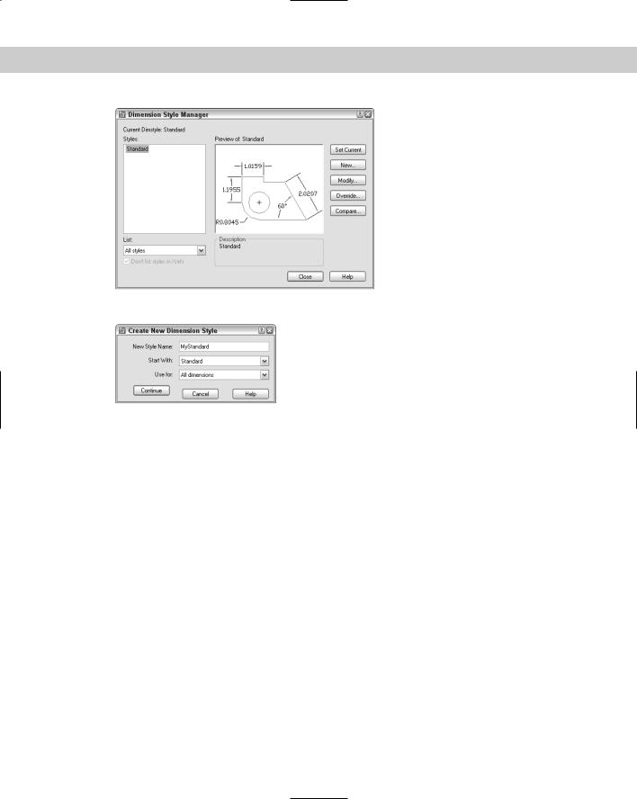
To create a dimension style, choose Dimension Style from the Dimension toolbar to open the Dimension Style Manager, shown in Figure 15-1. The current dimension style is shown as Standard, which is the default dimension style.
The Dimension Style Manager is the master control room where you manage dimensions. Here you create new dimension styles and modify existing ones.
The preset Standard dimension style is most appropriate for mechanical drafting. Whichever type of drafting you do, you’ll probably find the need to make some changes to the default dimension style or create a new dimension style. A preview of the current dimension style is shown at the right side of the dialog box.
To create a new style, click New to open the Create New Dimension Style dialog box, shown in Figure 15-2. Type a new name in the Name text box. In the Start With drop-down list, choose which existing dimension style you want to use as a basis for the new dimension style. If you have more than one to choose from, choose the style that most resembles the new style you want to create.
15C H A P T E R
In This Chapter
Understanding dimension styles
Defining a new dimension style
Changing dimension styles
Creating geometric tolerances
378 Part II Drawing in Two Dimensions
Figure 15-1: The Dimension Style Manager.
Figure 15-2: The Create New Dimension Style dialog box.
The Use For drop-down list lets you decide if you want to use the dimension style for all dimensions or only for a specific type of dimension. Usually, you create a dimension style for all dimension types. Later in this chapter, I explain how to create variants of dimension styles for specific types of dimensions, such as angular dimensions or leaders. When you’re done, click Continue.
You can also use the Dimension Style Manager to rename a dimension style. Click its name to select it. Click it a second time to see an edit box. Type the new name and press Enter.
Defining a New Dimension Style
Dimension styles have many components, so the process of defining a dimension style is complex. Your task is organized for you by the tabs of the dialog box.
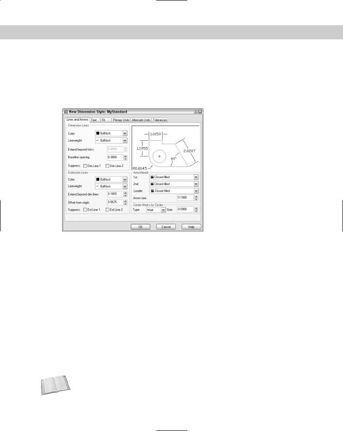
When you click Continue in the New Dimension Style dialog box, a second New Dimension Style dialog box opens, as shown in Figure 15-3.
The New Dimension Style dialog box has the following tabs:
Lines and Arrows: Sets specifications for dimension lines, extension lines, arrowheads, and center marks
Text: Determines the appearance, placement, and alignment of dimension text
Fit: Sets how text and arrows fit inside narrow dimensions, where text is placed when it doesn’t fit in its default position, the scale factor for dimension features, and whether to place a dimension line inside narrow dimensions
Chapter 15 Creating Dimension Styles and Tolerances |
379 |
Primary Units: Determines the format and precision for the primary measuring unit for both linear and angular dimensions
Alternate Units: Determines the format and precision for secondary units, if turned on (such as metric measurements if your primary units are English, or vice versa)
Tolerances: Formats tolerances
Figure 15-3: The New Dimension Style dialog box with the Lines and Arrows tab displayed.
Managing dimension lines and arrows
An important part of defining a dimension style is specifying how the dimension lines and arrows look, which you do on the Lines and Arrows tab of the New Dimension Style dialog box. In Chapter 14, Figure 14-1, I illustrate the parts of a dimension. Refer to that figure if you need a refresher. The Lines and Arrows tab is divided into four sections: Dimension Lines, Extension Lines, Arrowheads, and Center Marks for Circles.
Dimension lines
To set the color of the dimension line so that it differs from that of the rest of the dimension, click the Color drop-down list and choose a color. Choose Select Color to open the Select Color dialog box if you want to use a nonstandard color. Remember, dimensions are blocks — one object. The default color is ByBlock so that dimensions take on the color of the current layer or color setting. In general, you should have a separate layer for dimensions. Then the entire dimension is the color set for that layer. Use this setting only if you want the dimension lines to be a different color from your dimension layer color. The arrowheads do not have a separate color setting and always follow the dimension-line setting.
Cross- |
See Chapter 11 for a discussion of how to use the Select Color dialog box. See Chapter 18 for |
Reference |
coverage of blocks. |
|
380 Part II Drawing in Two Dimensions
To set a lineweight for the dimension line, click the Lineweight drop-down list and choose a lineweight. The default lineweight is ByBlock, which means that the lineweight will follow the lineweight of the dimension’s layer. In general, you want your objects to stand out, so dimensions should have a lineweight the same as or lower than the objects you’re dimensioning.
The Extend Beyond Ticks text box determines how far the dimension lines extend past the extension lines. When you have arrowheads at the ends of the dimension lines, the Extension option is unavailable. However, if you choose Architectural Tick, Oblique, Dot Small, Integral, or None in the Arrowheads section of the dialog box, the Extend Beyond Ticks option becomes available. This type of extension is typical for architectural drafting. Figure 15-4 shows a dimension with an architectural tick and a 0.1-unit extension.
Extension
Architectural tick
Figure 15-4: A typical architectural dimension showing the text above one dimension line, an architectural tick, and the dimension line extending slightly beyond the extension lines.
The Baseline spacing text box determines the distance between successive dimension lines when you create baseline dimensions. This specification creates evenly spaced dimension lines.
In some dimension styles, the dimension text splits the dimension line into two parts, as shown in Figure 15-5. This creates two dimension lines. You can suppress — that is, turn off — the first or second dimension line (or both dimension lines) by checking the appropriate box (or boxes). The first line is nearest where you specified the first extension-line origin. (If you selected an object instead of specifying two extension-line origins, you may not be able to predict which dimension line is the first and which is the second. Experiment.) You would usually suppress dimension lines when they interfere with other dimensions or with objects in your drawing.
Extension lines
As with dimension lines, you can pick a color for the extension lines that differs from that of the rest of the dimension. Click the Color drop-down list and choose a color. Choose Select Color to open the Select Color dialog box if you want a nonstandard color. The default color is ByBlock so that extensions take on the color of the current layer or color setting.
Extension lines typically extend slightly past the dimension line, as you can see in some of the figures in this chapter. Use the Extend Beyond Dim Lines text box to specify this extension distance.
Extension lines don’t usually touch the object they dimension to make it easier to distinguish the dimension from the object. Use the Offset from Origin text box to define the distance from the specified points on the object to the extension lines.
Chapter 15 Creating Dimension Styles and Tolerances |
381 |
First dimension line |
Second dimension line |
First point selected |
Second point selected |
Figure 15-5: A typical mechanical dimension with text splitting two dimension lines.
You manage extension lines similarly to dimension lines. You can suppress the first or second extension line (or both lines) so that either or both are not visible — check the appropriate box (or boxes). Figure 15-6 shows a dimension with the first extension line suppressed.
Figure 15-6: A dimension with the first extension line suppressed.
Arrowheads
The Arrowheads section controls the arrowheads that go at the ends of dimension lines. You don’t actually have to use arrowheads, as you saw in Figure 15-4. You can also set the first and second arrowheads individually. However, if you change the first arrowhead, the second one follows suit, assuming that you want both ends of the dimension to look the same. To make them different, specify your choice in the first drop-down box, and then in the second dropdown box.
382 Part II Drawing in Two Dimensions
You can create and use your own arrowhead:
1.In any drawing, create the arrowhead you want with a unit size of 1.
2.Make a block out of it. For an arrow-shaped block, pick the point of the arrow for the insertion point and create it pointing to the right. You may have to experiment with the right insertion point. Save the block. (See Chapter 18 for instructions on creating blocks.)
3.In the first and second drop-down lists, choose User Arrow. The Select Custom Arrow Block dialog box opens, displaying the blocks available in the drawing.
4.Choose the block you want from the drop-down list.
5.Click OK.
Figure 15-7 shows a dimension with a user arrow.
Figure 15-7: A dimension with a user arrow.
Tip |
You can set a different arrow for leaders. Choose the arrow you want from the Leader drop- |
|
down list. |
|
Set the size of the arrowhead in the Arrow Size text box. As explained later in this chapter in |
|
the discussion of scale, you should use the final size you want to see when the drawing is |
|
plotted on paper. |
|
Center marks |
|
The Center Marks for Circles section of the New Dimension Style dialog box specifies how |
|
you want to mark the centers of arcs and circles when you choose Center Mark from the |
|
Dimension toolbar (the DIMCENTER command). From the Type drop-down list, choose Mark |
|
to create a small cross, Line to create a cross plus four lines that cross, or None. Figure 15-8 |
|
shows a circle with centerlines and an arc with a center mark. |
Figure 15-8: A circle with a centerline and an arc with a center mark.

Chapter 15 Creating Dimension Styles and Tolerances |
383 |
Specify the size of the center mark or centerline in the Size text box. For center marks, the size is the distance from the intersection of the two lines to their endpoints. If you use centerlines, the size also determines the distance from the circle quadrants to the end of the centerlines.
Because the Standard dimension style is closest to mechanical drafting standards, in the following exercise (and others in this chapter), you start to create an architectural dimension style using the Standard style as a base. This requires you to make a maximum number of changes, thereby letting you become as familiar as possible with the dimension style settings. Here you practice controlling dimension lines and arrows.
On the |
The drawing used in the following Step-by-Step exercise on controlling dimension lines and |
CD-ROM |
arrows, ab15-a.dwg, is in the Drawings folder on the CD-ROM. |
STEP-BY-STEP: Controlling Dimension Lines and Arrows
1.Open ab15-a.dwg from your CD-ROM.
2.Save the file as ab15-01.dwg in your AutoCAD Bible folder. This drawing is an elevation of a garage, as shown in Figure 15-10. ORTHO and OSNAP should be on. Set running object snaps for endpoint and intersection. The Dim layer is current. If the Dimension toolbar is not visible, right-click any toolbar and choose Dimension.
3.To see what the Standard dimension style looks like, choose Linear Dimension from the Dimension toolbar. At the Specify first extension line origin or <select object>: prompt, pick 1 in Figure 15-9. At the Specify second extension line origin: prompt, pick 2. At the Specify dimension line location or [Mtext/ Text/Angle/Horizontal/Vertical/Rotated]: prompt, pick a location for the dimension line below the line you dimensioned. The arrows and text are so small
you can’t even see them.
1 |
2 |
Figure 15-9: The garage elevation.

384 Part II Drawing in Two Dimensions
4.Use a Zoom Window to zoom in on 1 and the left end of the dimension. Choose Zoom Previous from the Standard toolbar. Zoom in on the center of the dimension to see the text. Choose Zoom Previous again. As you can see, this dimension needs some modification.
5.Choose Dimension Style from the Dimension toolbar. The current dimension style should be Standard. Click New. In the New Style Name text box, type Arch 48 and click Continue.
6.Click the Lines and Arrows tab if it isn’t on top. In the Arrowheads section, choose Oblique from the first drop-down list. The size should be 3/16". In the Dimension Lines section, type 3/32 in the Extend beyond Ticks text box. (Due to the units precision setting — set by choosing Format Units — this value is rounded off to 1/8" in the display, although the value is still 3/32.) Click OK to return to the Dimension Style Manager.
7.In the Dimension Style Manager, notice that the arrows have been changed to ticks in the preview. Click Set Current. Click Close.
8.Select the dimension you created in Step 3. In the Dim Style Control drop-down list on the Dimension toolbar, choose Arch 48. The dimension now has the geometry settings you just made. To check it out, do a Zoom Window to the left end of the dimension.
You can see that the oblique mark has replaced the arrow. Do a Zoom Previous.
9.Save your drawing. Keep this drawing open if you’re continuing on to the next exercise.
Managing dimension text
You can format the text of the dimension for readability and to match other text in your drawing. In the New Dimension Style dialog box, the Text tab, shown in Figure 15-10, controls text appearance, placement, and alignment.
Figure 15-10: The Text tab of the New Dimension Style dialog box.
Chapter 15 Creating Dimension Styles and Tolerances |
385 |
Text appearance
You have full control over dimension text appearance, as you do over any other text in your drawing. To specify a text style for your dimension text, choose a text style from the Text style drop-down list. You may want to create a special text style, such as Dim Text, for dimension text to give you the flexibility to alter dimension text without changing other text in your drawing. Create the dimension text style before creating your dimension style.
Cross- |
See Chapter 13 for a discussion of text styles. |
Reference |
|
Choose a color from the Text Color drop-down list. You can pick a color for the dimension text that differs from that of the rest of the dimension. The default color is ByBlock so that dimensions take on the color of the current layer or color setting. Use this setting only if you want the dimension text to be a different color from your dimension layer color. To choose a nonstandard color, choose Select Color from the drop-down list to open the Select Color dialog box.
Choose the height for your dimension text. When you set the text style height to zero, you can set the height in the New Dimension Style dialog box. Otherwise, the text style height takes over. It’s much easier to make all your dimension style adjustments in one place than to make changes in the text style as well.
If your unit type uses fractions, use the fraction height scale to set a ratio of fraction text to whole text. This option is only available if your units specify the use of fractions. You may want the fractions to be smaller than whole numbers. A scale of 0.5 makes the fractions half the size of whole numbers; the resulting overall fraction is slightly higher than the whole numbers of the dimension text.
Text placement
The Vertical drop-down list affects how text is justified relative to the dimension line. As you make changes, be sure to look at the preview to see if the results are what you want. You have the following options:
Centered: Centers the text in the dimension line, breaking the dimension line into two. This is typical for mechanical drafting. You can see an example in Figure 15-5.
Above: Places text above the dimension line. This is typical for architectural drafting. You can see an example in Figure 15-4.
Outside: Places the text on the side of the dimension line that is farthest from the object you’re dimensioning.
JIS: Places text in conformation to the Japanese Industrial Standards rules, which vary the placement according to the angle of the dimension line.
The Horizontal drop-down list affects the placement of dimension text between the extension lines. Here again, you have a handy visual confirmation of your choice. You have the following choices:
Centered: This is the default. It centers text between the two extension lines.
At Ext Line 1: Places the text next to the first extension line. The first extension line is always the first point you specified at the Specify first extension line origin or <select object>: prompt. The picture and the words Horizontal Justification can be especially confusing for vertical dimensions. If you aren’t consistent in how you pick your dimensions, you can get some strange results.
386 Part II Drawing in Two Dimensions
At Ext Line 2: Places the text next to the second extension line. The comments for the previous option apply to this option as well.
Over Ext Line 1: Places the text over the first extension line. The comments for the At Ext Line 1 option apply to this option as well.
Over Ext Line 2: Places the text over the second extension line. The comments for the At Ext Line 1 option apply to this option as well.
Use the Offset from Dim Line text box to set the gap between the dimension text and the dimension line. If the dimension line is broken, the gap is the space between each side of the dimension text and the two dimension lines. If the dimension line is unbroken and the text is above the line, the gap is the space between the bottom of the text and the dimension line. The gap also controls the space between the box created for Basic tolerance dimensions and the text inside them. Basic tolerances are discussed in the “Formatting tolerances” section later in this chapter.
Tip |
When trying to fit dimension text, lines, and arrows in a narrow space, AutoCAD and AutoCAD |
|
LT also use the gap to calculate the minimum space required on either side of the dimension |
|
text. Reducing the gap can, therefore, help fit more of the dimension elements between the |
|
extension lines. |
Text alignment
Different disciplines have different standards for aligning dimension text. The Alignment section of the Text tab affects how the text is aligned relative to the dimension line, as follows:
On the
CD-ROM
Horizontal: Keeps text between the extension lines horizontal, regardless of the angle of the dimension line (typical of mechanical drawings).
Aligned with Dimension Line: Keeps text at the same angle as the dimension line (typical of architectural drawings).
ISO Standard: Uses the ISO standard, which aligns text with the dimension line when text is inside the extension lines, but aligns text horizontally when text is outside the extension lines (because of a tight fit).
The drawing used in the following Step-by-Step exercise on defining dimension text, ab1501.dwg, is in the Results folder on the CD-ROM.
STEP-BY-STEP: Defining Dimension Text
1.If ab15-01.dwg is open from the previous exercise, use it for this exercise as well. Otherwise, open ab15-01.dwg from the Results folder of the CD-ROM. ORTHO and OSNAP should be on. Set running object snaps for endpoint and intersection. The Dim layer is current. If the Dimension toolbar is not visible, right-click any toolbar and choose Dimension.
2.Save the file as ab15-02.dwg in your AutoCAD Bible folder.
3.Choose Dimension Style from the Dimension toolbar. The Arch 48 dimension style should be current. Choose Modify to continue working on the Arch 48 dimension style. Click the Text tab.
Chapter 15 Creating Dimension Styles and Tolerances |
387 |
4.In the Text Appearance section, choose ROMANS as the text style.
5.In the Text Placement section, choose Above from the Vertical drop-down list.
6.In the Text Alignment section, choose Aligned with dimension line. Although mechanical dimensions usually require horizontal text, architectural dimensions require that the text be aligned with the dimension line.
7.Click OK and then click Close to update the dimension to include the changes. The text is still too tiny to see clearly.
8.Save your drawing. Keep this drawing open if you’re continuing on to the next exercise.
Fitting dimensions into tight spaces
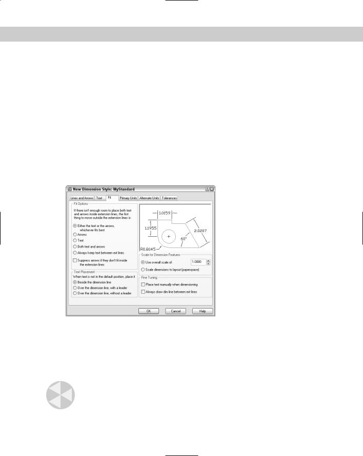
When there is not enough room to place the arrowheads, dimension line, and text between the extension lines, some elements of the dimension need to go outside the extension lines. The Fit tab, shown in Figure 15-11, lets you specify how you want to handle this situation.
Figure 15-11: The Fit tab of the New Dimension Style dialog box.
Fit Options
The Fit Options section determines what gets moved outside the extension lines — text, arrows, or both — when they can’t fit inside the extension lines. These are among the hardest of the dimension styles options to understand, yet they can greatly affect how your dimensions appear.
Caution |
The fit options specify what goes outside the extension lines. Before Release 2000, they spec- |
|
ified what goes inside the extension lines. Be careful — or you’ll get a result opposite of what |
|
you intended. |
388 Part II Drawing in Two Dimensions
Here are your choices:
Either the Text or the Arrows, Whichever Fits Best: Puts whatever fits inside the extension lines. The arrowheads might fit inside and the text not, or the other way around. Or if there isn’t enough room for either, they both go outside the extension lines. Figure 15-12 shows a dimension using this option.
Figure 15-12: A narrow dimension using the Either the
Text or the Arrows, Whichever Fits Best option.
Arrows: If there is not enough room for both the text and the arrows between the extension lines, the arrows go outside and the text goes between them. Figure 15-13 shows a dimension using this option. The results of this option happen to look the same as Figure 15-12, but a different setting produced them.
Figure 15-13: A narrow dimension using the Arrows option.
Text: If there isn’t enough room for the text and the arrows between the extension lines, the text goes outside and the arrows go between them. Figure 15-14 shows a dimension using this option.
Figure 15-14: A narrow dimension using the Text option.
Both Text and Arrows: Keeps the text and arrows together — between the extension lines if there is enough room, outside the extension lines if not. Figure 15-15 shows a dimension using this option.

Chapter 15 Creating Dimension Styles and Tolerances |
389 |
Figure 15-15: A narrow dimension using the Both Text and Arrows option.
Always Keep Text between Ext Lines: As it says, this option always keeps the text between the extension lines, even if they don’t fit. Figure 15-16 shows a dimension using this option.
Figure 15-16: A narrow dimension using the Always
Keep Text Between Ext Lines option.
Suppress Arrows if They Don’t Fit inside the Extension Lines: Use this check box to suppress the display of arrows completely if they don’t fit inside the extension lines (instead of putting them outside). This option is used together with one of the previous options. Figure 15-17 shows a dimension using this option with the Either the Text or the Arrows, Whichever Fits Best option.
Figure 15-17: A narrow dimension using the Suppress Arrows if They Don’t Fit inside the Extension Lines option along with the Either the Text or the Arrows, Whichever Fits Best option.
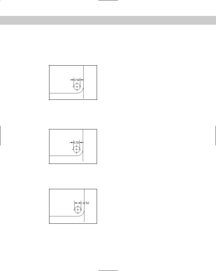
Text Placement
The Text Placement section determines where you want the dimension text when it isn’t in its default position, due to a tight fit. Your options are:
Beside the Dimension Line: Places the dimension text next to the dimension line, but outside the extension lines. Figure 15-18 shows a dimension using this option as well as the same dimension edited to move the text off the model. You can move the text anywhere to the left or the right of the dimension line, but not above or below it. Editing dimensions is covered later in this chapter.
390 Part II Drawing in Two Dimensions
Figure 15-18: Dimension text is placed beside the dimension line when it doesn’t fit inside the extension lines. You can move the text from side to side. On the right, the text has been moved to the right slightly so that it doesn’t cross the model.
Over the Dimension Line, with a Leader: Places the dimension text over the dimension line, between the extension lines, but above them, with a leader from the dimension line to the text. You can move the text anywhere to suit your needs and dimensioning conventions, as shown in Figure 15-19.
Figure 15-19: Dimension text is placed over the dimension line with a leader. On the right, the text has been moved to the right of the model.
Over the Dimension Line, without a Leader: Places the dimension text over the dimension line, between the extension lines, but above them, with no leader, as shown in Figure 15-20. You can move the text anywhere.
Figure 15-20: Dimension text is placed over the dimension line without a leader.
Scale for Dimension Features
The Scale for Dimension Features section lets you specify the scale factor. The scale factor adjusts the size of dimension text (unless a nonzero text style height controls the text), arrowheads, spacing, and so on. It has no effect on the content of dimension text — that is, it does
Chapter 15 Creating Dimension Styles and Tolerances |
391 |
not affect actual measurements. So many size options are possible in a dimension style that you could spend all day trying to multiply each size option by the scale. Then, if you have to change the scale of the drawing, you would need to recalculate all the size specifications. Setting the Overall Scale factor makes your life easier because AutoCAD or AutoCAD LT automatically multiplies every size specification by the scale factor.
Cross- |
Scale factors are discussed in detail in Chapter 5. See Chapter 17 for a discussion of scaling |
Reference |
dimensions in a paper space layout. |
|
In the Fine Tuning section, if you check Place Text Manually when Dimensioning, the horizontal text placement settings are ignored and the point you pick at the Specify dimension line location or [Mtext/Text/Angle/Horizontal/Vertical/ Rotated]: prompt is used.
Before you click, as you move the cursor along the dimension line, you can see the text following the cursor.
Check Always Draw Dim Line Between Ext Lines to force a dimension line between the extension lines even when there isn’t room for text or arrows, as shown in Figure 15-21.
Figure 15-21: A dimension with a dimension line forced.
On the |
The drawing used in the following Step-by-Step exercise on setting dimension fit, ab15- |
CD-ROM |
02.dwg, is in the Results folder on the CD-ROM. |
STEP-BY-STEP: Setting Dimension Fit
1.If ab15-02.dwg is open from the previous exercise, use it for this exercise as well. Otherwise, open ab15-02.dwg from the Results folder of the CD-ROM. ORTHO and OSNAP should be on. Set running object snaps for endpoint and intersection. The Dim layer is current. If the Dimension toolbar is not visible, right-click any toolbar and choose Dimension.
2.Save the file as ab15-03.dwg in your AutoCAD Bible folder.
3.Choose Dimension Style from the Dimension toolbar. Make sure the Arch 48 dimension style is current. Choose Modify to continue working on the Arch 48 dimension style.
4.On the Fit tab, in the Text Placement section, choose Over the Dimension Line, with a Leader.
5.In the Fine Tuning section, check Always Draw Dim Line Between Ext Lines. Architectural dimensions customarily place a line between the extension lines even if the text cannot fit.
6.Because the drawing’s scale is 1⁄4"=1', or 1:48, type 48 in the Use Overall Scale Of text box.
7.Click OK. Click Close to return to your drawing.
8.Save your drawing. You can finally see the dimension! It should look like Figure 15-22. Keep this drawing open if you’re continuing on to the next exercise.

392 Part II Drawing in Two Dimensions
Figure 15-22: As a result of changing the overall scale, you can finally see the dimension.
Defining primary units
The primary units define the type of units used to display the dimension in your drawing. You need to set primary units separately from the units for the drawing, which affect coordinate display but not dimensions.
Click the Primary Units tab, shown in Figure 15-23, to set the format and precision for linear and angular dimensions. You should already be familiar with setting units, which I discuss in Chapter 5. You must separately set your units for dimensions.
Figure 15-23: The Primary Units tab of the New Dimension Style dialog box.

Chapter 15 Creating Dimension Styles and Tolerances |
393 |
Linear Dimensions
To get the look and accuracy that you want, you should specify the format and precision of your linear dimensions. The Linear Dimensions section provides settings for linear dimensions. You have the following options
Choose a format from the Unit format drop-down list. You have the same choices as in the Drawing Units dialog box: Scientific, Decimal, Engineering, Architectural, and Fractional, as well as an additional option — Windows Desktop.
Note |
To see the current Windows Desktop units setting, choose Start Settings Control Panel |
|
Regional Settings (or Regional Options, depending on your operating system). Click the |
|
Number tab. The Windows Desktop setting does not give you complete control over units. |
|
However, if you need consistency with another Windows application, you might find this set- |
|
ting useful. |
Choose a precision (the number of decimal points or the fraction denominator) from the Precision drop-down list.
Choose a fraction format from the Fraction Format drop-down list. This option is only available if the format you chose uses fractions. Horizontal places a horizontal line between stacked numerators and denominators. Diagonal uses a diagonal slash between the stacked numerator and denominator. Not Stacked uses a diagonal line between the numerator and denominator, which are not stacked. You can see the effect of each choice in the preview box.
Choose a decimal separator. This option is only available if the format you chose uses decimals. You can choose from a period, a comma, and a space.
Use the Round Off text box to round off linear dimension distances. For example, you can round to the nearest 0.1 unit or 1⁄2 inch.
Use the Prefix and Suffix boxes to add a prefix or suffix that you want to place before or after every dimension. For example, you might want to add a suffix of mm after every dimension if you’re measuring in millimeters and giving the drawing to a client who usually sees dimensions in inches.
You can use the Scale Factor text box to set a scaling factor for linear dimensions, including radial and diameter dimensions, and ordinal dimensions. This factor changes the actual measurement text. For example, if you draw a line 2.5 units long and you specify a linear scale
of 0.5, the object is dimensioned as 1.25 units. You could set this scale to 25.4 to use metric measurements on a drawing you have created with U.S. measurements — perhaps you’re sending the same drawing to certain clients in the United States and other clients elsewhere in the world. You can also use this scale in conjunction with alternate units, as explained in the next section.
Check Apply to Layout Dimension Only to apply the linear scaling factor only to layout (paper space) dimensions.
Under Zero Suppression, choose if you want to suppress leading and trailing zeros. If you suppress leading zeros, a number such as 0.375 appears as .375. If you suppress trailing zeros, a number such as 3.7500 appears as 3.75.
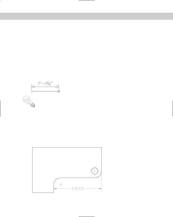
For architectural units, you can choose to suppress 0 feet and 0 inches. If you suppress
0 feet, a number such as 0'-8" becomes 8". If you suppress 0 inches, a number such as 6'-0" becomes 6'.

394 Part II Drawing in Two Dimensions
Angular Dimensions
To get the look and accuracy that you need for angular dimensions, you should also set their format and precision. The Angular Dimensions section of the Primary Units tab lets you format angular measurements. You have the following options:
Choose from Decimal Degrees, Degrees Minutes Seconds, Gradians, and Radians.
Choose a precision from the Precision drop-down list.
Under Zero Suppression, choose if you want to suppress leading and trailing zeros for angular dimensions. For example, an angle of 37.0° would appear as 37° with the trailing zero suppressed.
Defining alternate units
If you want, you can show an alternate set of units in your dimensions. The most common use of this feature is to show millimeters and inches together. Alternate units appear in square brackets. To show alternate units, click the Alternate Units tab of the New Dimension Style dialog box, as shown in Figure 15-24. Check the Display Alternate Units check box.
Figure 15-24: The Alternate Units tab.
As you can see, this dialog box is very similar to the Primary Units tab, discussed in the previous section. Notice the default scale of 25.40 in the Multiplier for Alt Units text box. There are 25.4 millimeters to an inch. If your primary units are millimeters, you can set the linear scale to 0.03937, which is the number of inches to a millimeter. Of course, if your units are not inches but meters, miles, or something else, you need to make the appropriate calculations.
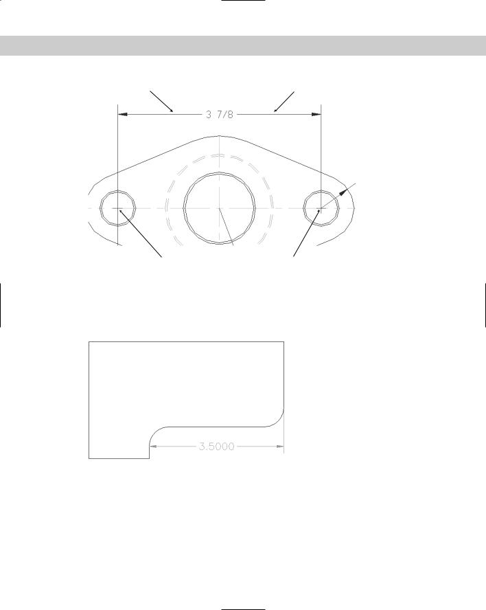
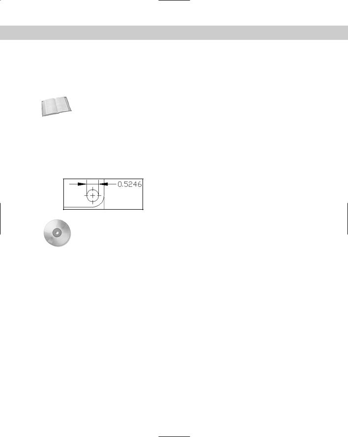
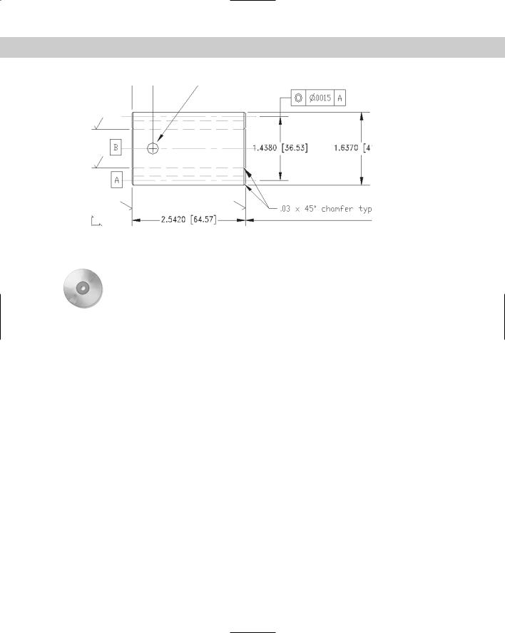
Figure 15-25 shows two dimensions with alternate units.
In the Placement section, choose one of the options to place alternate units after or below the primary units.
Chapter 15 Creating Dimension Styles and Tolerances |
395 |
Figure 15-25: Dimensions showing both U.S. and metric measurements.
Thanks to Jerry Bottenfield of Clow Valve Company, Oskaloosa, Iowa, for this drawing.
On the |
The drawing used in the following Step-by-Step exercise on defining primary units, ab15-03. |
CD-ROM |
dwg, is in the Results folder on the CD-ROM. |
STEP-BY-STEP: Defining Primary Units
1.If ab15-03.dwg is open from the previous exercise, use it for this exercise as well. Otherwise, open ab15-03.dwg from the Results folder of the CD-ROM. ORTHO and OSNAP should be on. Set running object snaps for endpoint and intersection. The Dim layer is current. If the Dimension toolbar is not visible, right-click any toolbar and choose Dimension.
2.Save the file as ab15-04.dwg in your AutoCAD Bible folder.
3.Choose Dimension Style from the Dimension toolbar. The Arch 48 dimension style should be current. Choose Modify to continue working on this dimension style. Click the Primary Units tab.
4.In the Unit Format drop-down list, choose Architectural.
5.In the Precision drop-down list, change the precision to 0'-0 1/8".
6.In the Fraction format drop-down list, choose Diagonal.
7.In the Zero Suppression section, uncheck the 0 Inches check box because architectural dimensions sometimes show 0 inches.
8.Click the Text tab. In the Fraction Height Scale text box, type .75.
9.Click OK. In the Dimension Style Manager, click Set Current and then click Close to return to your drawing. The dimension is automatically updated and now looks appropriate for an architectural drawing.
10.To see how the stacked fractions appear, create a linear dimension from 1 to 2 in Figure 15-26. If necessary, zoom in to see the dimension text clearly.

396 Part II Drawing in Two Dimensions
1 2
Figure 15-26: The dimension style is now complete.
11.Return to the previous view if you zoomed in. Save your drawing. It should look like Figure 15-26.
Formatting tolerances
Tolerances are used in mechanical drafting to specify how much deviation is allowed from the exact measurement when the model is manufactured. Format the tolerance notation on the Tolerances tab of the New Dimension Style dialog box. The Tolerances tab is shown in Figure 15-27.
Figure 15-27: The Tolerances tab of the New Dimension Style dialog box.
Chapter 15 Creating Dimension Styles and Tolerances |
397 |
Use the Tolerance Format section to specify how you want the tolerances to be displayed. You can choose from four tolerance methods from the Method drop-down list:
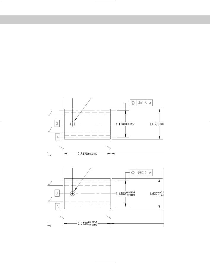
Symmetrical tolerances have the same upper and lower amounts and are shown with a plus/minus sign, as shown in Figure 15-28. The Upper Value text box is active so that you can type in the tolerance amount.
Deviation tolerances can have different upper and lower amounts and are therefore shown after separate plus and minus signs, as shown in Figure 15-29. When you choose a deviation tolerance, the Upper Value and Lower Value text boxes become active.
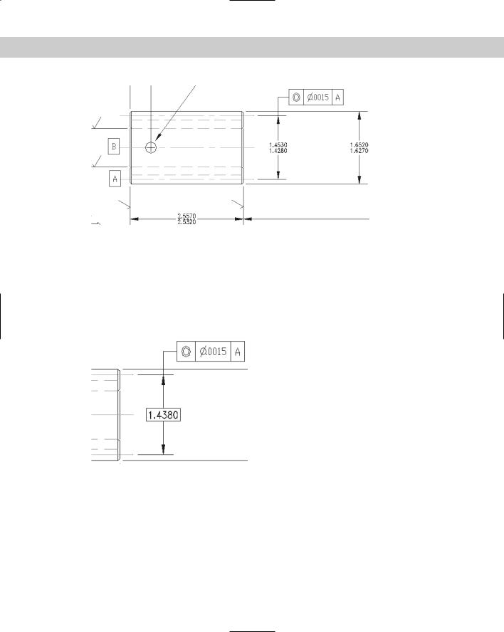
Limits tolerances include the upper and lower tolerances in the measurement, as shown in Figure 15-30. Use the Upper Value and Lower Value text boxes to type in the upper and lower tolerance amounts.
Basic dimensions place the dimension in a box, as shown in Figure 15-31.
Figure 15-28: Symmetrical tolerances.
Figure 15-29: Deviation tolerances.
398 Part II Drawing in Two Dimensions
Figure 15-30: Limits tolerances.
In the Precision drop-down list, choose a precision. Use the Upper Value text box to set the tolerance value for symmetrical tolerances. For deviation and limits tolerances, use both the Upper Value and Lower Value text boxes.
The Scaling for Height text box lets you scale the height of the tolerance relative to the dimension text height. Using smaller text for the tolerances is common. A value of 1 creates tolerance text equal to the dimension text height. A setting of 0.5 creates tolerance text that is half the size of regular dimension text.
Figure 15-31: A Basic dimension.
Use the Vertical Position drop-down list to determine how the tolerances are aligned with the main dimension text. This setting has the most effect on Deviation tolerances that display two lines of text for the one dimension text line. You have the following choices:
Top: Aligns the tolerance text with the top of the dimension text.
Middle: Aligns the tolerance text with the middle of the dimension text.
Bottom: Aligns the tolerance text with the bottom of the dimension text.