

- •Foreword
- •Preface
- •Is This Book for You?
- •How This Book Is Organized
- •How to Use This Book
- •Doing the Exercises
- •Conventions Used in This Book
- •What the Icons Mean
- •About the CD-ROM
- •Other Information
- •Contacting the Author
- •Acknowledgments
- •Contents at a Glance
- •Contents
- •Getting Acquainted with AutoCAD and AutoCAD LT
- •Starting AutoCAD and AutoCAD LT
- •Creating a New Drawing
- •Using the AutoCAD and AutoCAD LT Interface
- •Creating Your First Drawing
- •Saving a Drawing
- •Summary
- •Creating a New Drawing from a Template
- •Working with Templates
- •Opening a Drawing with Default Settings
- •Opening an Existing Drawing
- •Using an Existing Drawing as a Prototype
- •Saving a Drawing Under a New Name
- •Summary
- •The Command Line
- •Command Techniques
- •Of Mice and Pucks
- •Getting Help
- •Summary
- •Typing Coordinates
- •Displaying Coordinates
- •Picking Coordinates on the Screen
- •Locating Points
- •Summary
- •Unit Types
- •Drawing Limits
- •Understanding Scales
- •Inserting a Title Block
- •Common Setup Options
- •The MVSETUP Command
- •Summary
- •Using the LINE Command
- •Drawing Rectangles
- •Drawing Polygons
- •Creating Construction Lines
- •Creating Rays
- •Summary
- •Drawing Circles
- •Drawing Arcs
- •Creating Ellipses and Elliptical Arcs
- •Making Donuts
- •Placing Points
- •Summary
- •Panning
- •The ZOOM Command
- •Aerial View
- •Named Views
- •Tiled Viewports
- •Snap Rotation
- •User Coordinate Systems
- •Isometric Drawing
- •Summary
- •Editing a Drawing
- •Selecting Objects
- •Summary
- •Copying and Moving Objects
- •Using Construction Commands
- •Creating a Revision Cloud
- •Hiding Objects with a Wipeout
- •Double-Clicking to Edit Objects
- •Grips
- •Editing with the Properties Palette
- •Selection Filters
- •Groups
- •Summary
- •Working with Layers
- •Changing Object Color, Linetype, and Lineweight
- •Working with Linetype Scales
- •Importing Layers and Linetypes from Other Drawings
- •Matching Properties
- •Summary
- •Drawing-Level Information
- •Object-Level Information
- •Measurement Commands
- •AutoCAD’s Calculator
- •Summary
- •Creating Single-Line Text
- •Understanding Text Styles
- •Creating Multiline Text
- •Creating Tables
- •Inserting Fields
- •Managing Text
- •Finding Text in Your Drawing
- •Checking Your Spelling
- •Summary
- •Working with Dimensions
- •Drawing Linear Dimensions
- •Drawing Aligned Dimensions
- •Creating Baseline and Continued Dimensions
- •Dimensioning Arcs and Circles
- •Dimensioning Angles
- •Creating Ordinate Dimensions
- •Drawing Leaders
- •Using Quick Dimension
- •Editing Dimensions
- •Summary
- •Understanding Dimension Styles
- •Defining a New Dimension Style
- •Changing Dimension Styles
- •Creating Geometric Tolerances
- •Summary
- •Creating and Editing Polylines
- •Drawing and Editing Splines
- •Creating Regions
- •Creating Boundaries
- •Creating Hatches
- •Creating and Editing Multilines
- •Creating Dlines
- •Using the SKETCH Command
- •Digitizing Drawings with the TABLET Command
- •Summary
- •Preparing a Drawing for Plotting or Printing
- •Creating a Layout in Paper Space
- •Working with Plot Styles
- •Plotting a Drawing
- •Summary
- •Combining Objects into Blocks
- •Inserting Blocks and Files into Drawings
- •Managing Blocks
- •Using Windows Features
- •Working with Attributes
- •Summary
- •Understanding External References
- •Editing an Xref within Your Drawing
- •Controlling Xref Display
- •Managing Xrefs
- •Summary
- •Preparing for Database Connectivity
- •Connecting to Your Database
- •Linking Data to Drawing Objects
- •Creating Labels
- •Querying with the Query Editor
- •Working with Query Files
- •Summary
- •Working with 3D Coordinates
- •Using Elevation and Thickness
- •Working with the User Coordinate System
- •Summary
- •Working with the Standard Viewpoints
- •Using DDVPOINT
- •Working with the Tripod and Compass
- •Getting a Quick Plan View
- •Shading Your Drawing
- •Using 3D Orbit
- •Using Tiled Viewports
- •Defining a Perspective View
- •Laying Out 3D Drawings
- •Summary
- •Drawing Surfaces with 3DFACE
- •Drawing Surfaces with PFACE
- •Creating Polygon Meshes with 3DMESH
- •Drawing Standard 3D Shapes
- •Drawing a Revolved Surface
- •Drawing an Extruded Surface
- •Drawing Ruled Surfaces
- •Drawing Edge Surfaces
- •Summary
- •Drawing Standard Shapes
- •Creating Extruded Solids
- •Drawing Revolved Solids
- •Creating Complex Solids
- •Sectioning and Slicing Solids
- •Using Editing Commands in 3D
- •Editing Solids
- •Listing Solid Properties
- •Summary
- •Understanding Rendering
- •Creating Lights
- •Creating Scenes
- •Working with Materials
- •Using Backgrounds
- •Doing the Final Render
- •Summary
- •Accessing Drawing Components with the DesignCenter
- •Accessing Drawing Content with Tool Palettes
- •Setting Standards for Drawings
- •Organizing Your Drawings
- •Working with Sheet Sets
- •Maintaining Security
- •Keeping Track of Referenced Files
- •Handling Errors and Crashes
- •Managing Drawings from Prior Releases
- •Summary
- •Importing and Exporting Other File Formats
- •Working with Raster Images
- •Pasting, Linking, and Embedding Objects
- •Summary
- •Sending Drawings
- •Opening Drawings from the Web
- •Creating Object Hyperlinks
- •Publishing Drawings
- •Summary
- •Working with Customizable Files
- •Creating Keyboard Shortcuts for Commands
- •Customizing Toolbars
- •Customizing Tool Palettes
- •Summary
- •Creating Macros with Script Files
- •Creating Slide Shows
- •Creating Slide Libraries
- •Summary
- •Creating Linetypes
- •Creating Hatch Patterns
- •Summary
- •Creating Shapes
- •Creating Fonts
- •Summary
- •Working with Menu Files
- •Customizing a Menu
- •Summary
- •Introducing Visual LISP
- •Getting Help in Visual LISP
- •Working with AutoLISP Expressions
- •Using AutoLISP on the Command Line
- •Creating AutoLISP Files
- •Summary
- •Creating Variables
- •Working with AutoCAD Commands
- •Working with Lists
- •Setting Conditions
- •Managing Drawing Objects
- •Getting Input from the User
- •Putting on the Finishing Touches
- •Summary
- •Understanding Local and Global Variables
- •Working with Visual LISP ActiveX Functions
- •Debugging Code
- •Summary
- •Starting to Work with VBA
- •Writing VBA Code
- •Getting User Input
- •Creating Dialog Boxes
- •Modifying Objects
- •Debugging and Trapping Errors
- •Moving to Advanced Programming
- •A Final Word
- •Installing AutoCAD and AutoCAD LT
- •Configuring AutoCAD
- •Starting AutoCAD Your Way
- •Configuring a Plotter
- •System Requirements
- •Using the CD with Microsoft Windows
- •What’s on the CD
- •Troubleshooting
- •Index
624 Part IV Drawing in Three Dimensions
NW isometric view
The NW isometric view shows your model from the corner between the left and the back views, as well as halfway between a side view and the top view. The VPOINT equiv-
alent is –1,1,1. Figure 22-12 shows the house from the NW isometric view.
Figure 22-12: The NW isometric view of the 3D house.
Using DDVPOINT
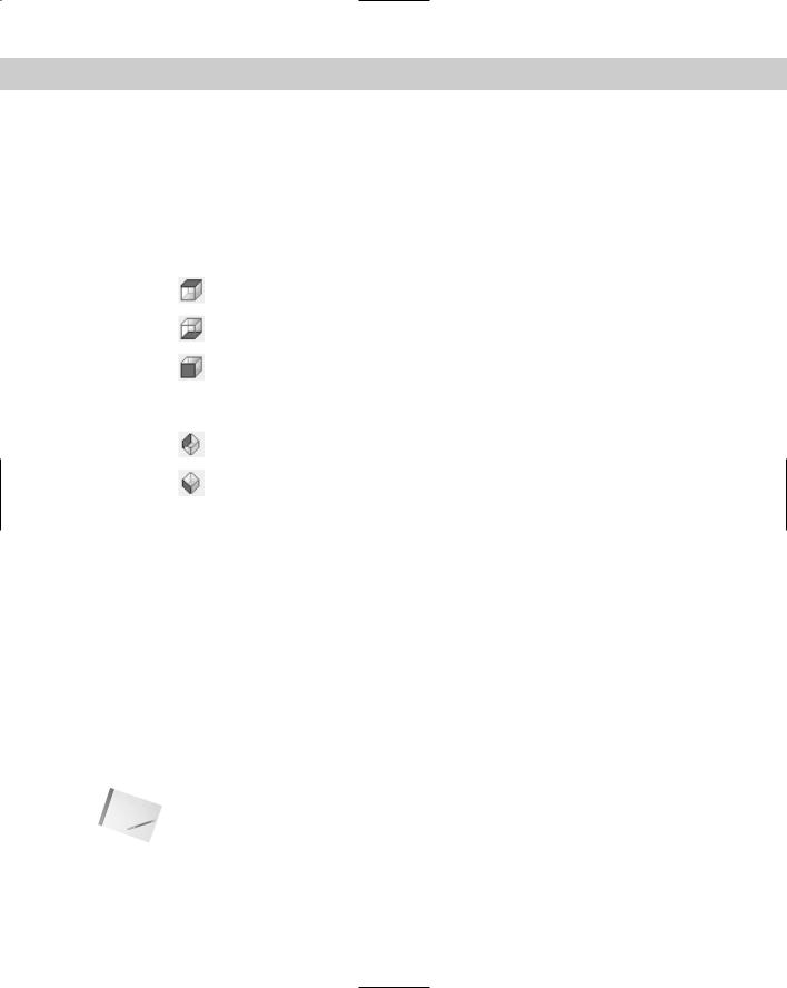
If the standard views aren’t sufficient for your needs, DDVPOINT can give you both flexibility and precision. To use this command, choose View 3D Views Viewpoint Presets to open the Viewpoint Presets dialog box, shown in Figure 22-13. This dialog box enables you to set the view to a great degree of accuracy.
Figure 22-13: The Viewpoint Presets dialog box.
Chapter 22 Viewing 3D Drawings 625
The left side of the dialog box determines the angle from the X axis in the XY plane. These angles work as follows:
270 |
Front view |
0 |
Right view |
90 |
Back view |
180 |
Left view |
|
Other angles result in viewpoints between these views. For example, an angle of 315 degrees |
|
enables you to look at your drawing from a view between front and right. If you’re thinking |
|
that this is similar to the SE isometric view, you’re correct. |
|
The right side of the dialog box determines the angle from the XY plane, in the Z direction. A |
|
0-degree angle enables you to look at your drawing from the front, back, or one side (eleva- |
|
tion views) — depending on the setting on the left part of the dialog box. Often you want to |
|
look at your drawing from above. A 90-degree angle shows you the plan view. An angle between |
|
0 and 90 gives you a slanted view from the top — such as one of the isometric standard views. |
|
(Actually, the isometric views set the angle from the XY plane to 35.3 degrees.) |
Tip |
There’s an art to using the two dials to set the view angle that you want. If you click the |
|
inside border of either one, close to the indicator needle, you set the angle based on exactly |
|
where you clicked. This results in uneven degrees, such as 47.6. However, if you click the out- |
|
side border of either image, or the numbers themselves, the angle is rounded to the value in |
|
the segment. |
|
When you open the dialog box, the black needles indicate the angles for the current view. When |
|
you change the angles, the black (or white) needles move to the new angle but the original |
|
needle remains to indicate the current angle. This enables you to constantly see the current |
|
angles for reference. |
|
Beneath the dials are text boxes that reflect your choices. You can simply type the angles you |
|
want in the text boxes. |
|
A very handy Set to Plan View button is at the bottom of the dialog box. This enables you to |
|
quickly return to plan view when you get a little dizzy from flying around your model. |
|
You can set the viewing angles either based on the WCS or relative to a different UCS that |
|
you’re using. It can get confusing if you have several different UCSs and start viewing them |
|
from several different viewpoints. As a result, the default is to view the drawing based on the |
|
WCS. However, sometimes you need to see your drawing relative to a UCS you’ve created. To |
|
do so, click Relative to UCS. |
Tip |
Keep the number of UCSs to the minimum necessary and save them. When possible, use a |
|
new viewpoint instead of creating a new UCS. |
|
Click OK after you finish making your changes. |
On the |
The drawing used in the following Step-by-Step exercise on using standard viewpoints and |
CD-ROM |
DDVPOINT, ab22-a.dwg, is in the Drawings folder on the CD-ROM. |
626 Part IV Drawing in Three Dimensions
STEP-BY-STEP: Using Standard Viewpoints and DDVPOINT
1.Open ab22-a.dwg from the CD-ROM.
2.Save it as ab22-01.dwg in your AutoCAD Bible folder. It shows the same house used in the earlier figures in this chapter from the SE isometric view.
3.Type ucsortho 0 to turn off the UCSORTHO system variable. Turning off UCSORTHO prevents the UCS from changing whenever you switch to one of the six orthogonal viewpoints.
4.Right-click any toolbar and choose View to open the View toolbar. Choose Top View from the Viewpoint toolbar.
5.Choose Bottom View from the Viewpoint toolbar. Notice that the small circle at the intersection of the X and Y axes disappears.
6.Choose Front View from the Viewpoint toolbar. You see the front of the house with the two strange bushes.
7. Choose Right View from the Viewpoint toolbar. You see the text “North side.”
8.Choose NW Isometric View from the Viewpoint toolbar. You’re looking at the back of the house.
9.Choose SW Isometric View from the Viewpoint toolbar. You’re looking at the front of the house. If you want, try the rest of the standard viewpoints.
10.Choose View 3D Viewpoint Viewpoint Presets to open the Viewpoint Presets dialog box. Set the left dial (angle from X axis) to 315 degrees by clicking the number 315. Set the right dial (angle from XY plane) to 60 degrees by clicking the second from the top segment pointed to by the number 60. Click OK. You see a view somewhat like the SE isometric view, but from much higher up.
11.Repeat the DDVPOINT command. In the X Axis text box, type 240. In the XY Plane text box, type 5. Click OK. You get a view from slightly off the ground, much as you might see it if you were walking up to the house.
12.Type hide . Notice that you can see the windows on the far side through the windows on your side of the house.
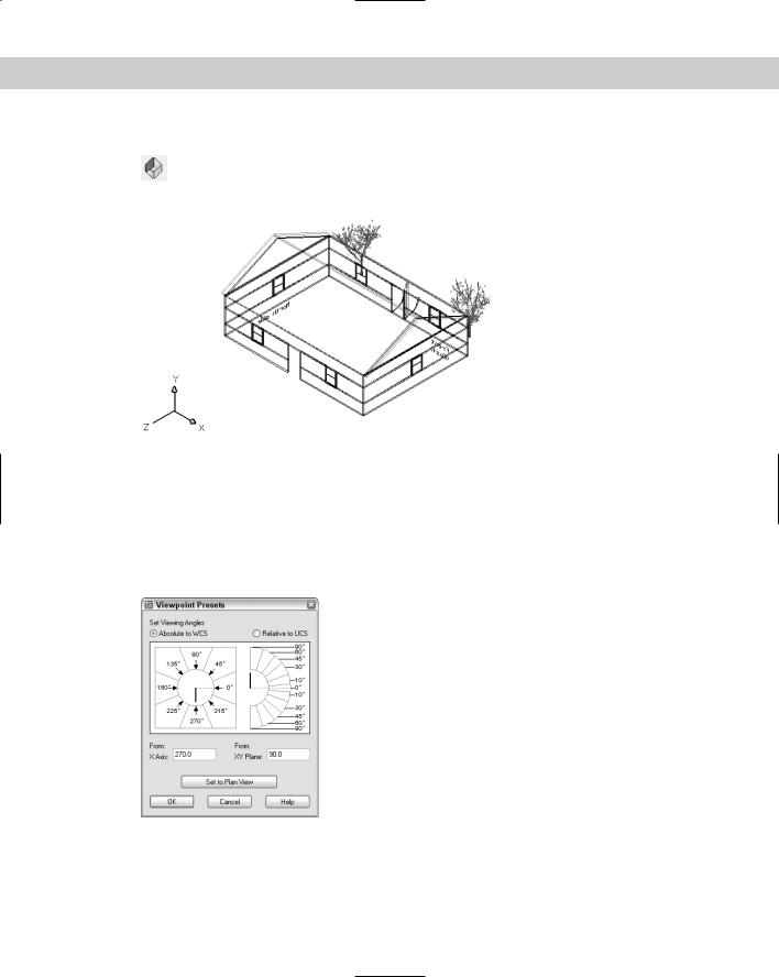
13.Choose View Named Views on the Named Views tab and click New. In the New View dialog box, type the name of the view, walk up. Click OK. Click OK again to return to your drawing. It should look like Figure 22-14.
14.If you’re working on someone else’s computer or want UCSORTHO on, type ucsortho 1 to turn it back on.
15.Save the drawing.
Note You cannot save the display that you see when you use the HIDE command. When you restore the view, you see it as a wireframe display. You can, however, make a slide of the view. Chapter 30 covers slides. You can also use SHADEMODE to continue working with the hidden view. Choose View Shade Hidden.

Chapter 22 Viewing 3D Drawings 627
Figure 22-14: The final view of the house.
Working with the Tripod and Compass
You can choose another method of defining views, using the VPOINT command. To start this command, choose View 3D Views Viewpoint. The tripod and compass appear, as shown in Figure 22-15.
Figure 22-15: The VPOINT tripod and compass are used to define viewpoints in 3D.
If you type the VPOINT command, or press Enter to repeat the command, press Enter at the
Current view direction: VIEWDIR=-1.0000,-1.0000,1.0000 Specify a view point or [Rotate] <display compass and tripod>: prompt to see the compass and tripod. (The numbers show the current viewpoint.)

628 Part IV Drawing in Three Dimensions
Move the cursor about, and two things happen. The cursor moves within the compass, and the axes dynamically shift position.
Imagine that you take a tangerine and make a large cross-shaped cut at the very bottom. Then you open out the bottom and remove the peel from the tangerine. Flatten the peel on the table. This is the concept of the compass, except that the outer edge is round. (The tangerine peel would have the shape of the cuts on its outer edge.) The very center of the compass — or the peel — is like the North Pole. When you’re over the North Pole, you’re looking straight down at your model — or the tangerine. This produces a plan view. The inner circle of the compass is where the middle of the tangerine was — at the equator. From the equator, you’re looking sideways (from the front, back, or side) at your model. The outer circle of the compass represents the South Pole. From over the South Pole, you’re looking at the bottom of your model — or the tangerine.
All of this is equivalent to the right image in the Viewpoint Presets dialog box that you use with the DDVPOINT command — it determines your view relative to the XY plane:
At the center of the compass, you’re right on top, looking down. This is a plan view.
At the inner circle, you’re on the side, looking at the XY plane on its edge.
At the outer circle, you’re beneath the XY plane, looking up.
The cross that goes through the compass represents the X and Y axes. If you place the cursor on the positive (right) side of the X axis, you’re looking at the tangerine from its right side — this is equivalent to a right view. The position of the cursor relative to the X and Y axes is equivalent to the left image in the Viewpoint Presets dialog box that you use with the DDVPOINT command — it determines your view relative to the X axis in the XY plane. To summarize, going clockwise:
The positive X axis gives you a right view.
The negative Y axis is equivalent to a front view.
The negative X axis gives you a left view.
The positive Y axis gives you a back view.
When you have the cursor at the desired location, simply click. Your drawing displays the viewpoint you specified.
You cannot get an exact viewpoint this way. However, some people find this method of defining a viewpoint more intuitive. You can also look at the tripod as the axes move about. But be careful — sometimes it’s difficult to see if an axis is coming toward you or going away from you.
Along with the tripod and compass, you see the current UCS icon based on the current UCS to help you get your bearings. Figure 22-16 shows a cursor location that results in the viewpoint shown in Figure 22-17. This is very close to the SE isometric view.