

- •Foreword
- •Preface
- •Is This Book for You?
- •How This Book Is Organized
- •How to Use This Book
- •Doing the Exercises
- •Conventions Used in This Book
- •What the Icons Mean
- •About the CD-ROM
- •Other Information
- •Contacting the Author
- •Acknowledgments
- •Contents at a Glance
- •Contents
- •Getting Acquainted with AutoCAD and AutoCAD LT
- •Starting AutoCAD and AutoCAD LT
- •Creating a New Drawing
- •Using the AutoCAD and AutoCAD LT Interface
- •Creating Your First Drawing
- •Saving a Drawing
- •Summary
- •Creating a New Drawing from a Template
- •Working with Templates
- •Opening a Drawing with Default Settings
- •Opening an Existing Drawing
- •Using an Existing Drawing as a Prototype
- •Saving a Drawing Under a New Name
- •Summary
- •The Command Line
- •Command Techniques
- •Of Mice and Pucks
- •Getting Help
- •Summary
- •Typing Coordinates
- •Displaying Coordinates
- •Picking Coordinates on the Screen
- •Locating Points
- •Summary
- •Unit Types
- •Drawing Limits
- •Understanding Scales
- •Inserting a Title Block
- •Common Setup Options
- •The MVSETUP Command
- •Summary
- •Using the LINE Command
- •Drawing Rectangles
- •Drawing Polygons
- •Creating Construction Lines
- •Creating Rays
- •Summary
- •Drawing Circles
- •Drawing Arcs
- •Creating Ellipses and Elliptical Arcs
- •Making Donuts
- •Placing Points
- •Summary
- •Panning
- •The ZOOM Command
- •Aerial View
- •Named Views
- •Tiled Viewports
- •Snap Rotation
- •User Coordinate Systems
- •Isometric Drawing
- •Summary
- •Editing a Drawing
- •Selecting Objects
- •Summary
- •Copying and Moving Objects
- •Using Construction Commands
- •Creating a Revision Cloud
- •Hiding Objects with a Wipeout
- •Double-Clicking to Edit Objects
- •Grips
- •Editing with the Properties Palette
- •Selection Filters
- •Groups
- •Summary
- •Working with Layers
- •Changing Object Color, Linetype, and Lineweight
- •Working with Linetype Scales
- •Importing Layers and Linetypes from Other Drawings
- •Matching Properties
- •Summary
- •Drawing-Level Information
- •Object-Level Information
- •Measurement Commands
- •AutoCAD’s Calculator
- •Summary
- •Creating Single-Line Text
- •Understanding Text Styles
- •Creating Multiline Text
- •Creating Tables
- •Inserting Fields
- •Managing Text
- •Finding Text in Your Drawing
- •Checking Your Spelling
- •Summary
- •Working with Dimensions
- •Drawing Linear Dimensions
- •Drawing Aligned Dimensions
- •Creating Baseline and Continued Dimensions
- •Dimensioning Arcs and Circles
- •Dimensioning Angles
- •Creating Ordinate Dimensions
- •Drawing Leaders
- •Using Quick Dimension
- •Editing Dimensions
- •Summary
- •Understanding Dimension Styles
- •Defining a New Dimension Style
- •Changing Dimension Styles
- •Creating Geometric Tolerances
- •Summary
- •Creating and Editing Polylines
- •Drawing and Editing Splines
- •Creating Regions
- •Creating Boundaries
- •Creating Hatches
- •Creating and Editing Multilines
- •Creating Dlines
- •Using the SKETCH Command
- •Digitizing Drawings with the TABLET Command
- •Summary
- •Preparing a Drawing for Plotting or Printing
- •Creating a Layout in Paper Space
- •Working with Plot Styles
- •Plotting a Drawing
- •Summary
- •Combining Objects into Blocks
- •Inserting Blocks and Files into Drawings
- •Managing Blocks
- •Using Windows Features
- •Working with Attributes
- •Summary
- •Understanding External References
- •Editing an Xref within Your Drawing
- •Controlling Xref Display
- •Managing Xrefs
- •Summary
- •Preparing for Database Connectivity
- •Connecting to Your Database
- •Linking Data to Drawing Objects
- •Creating Labels
- •Querying with the Query Editor
- •Working with Query Files
- •Summary
- •Working with 3D Coordinates
- •Using Elevation and Thickness
- •Working with the User Coordinate System
- •Summary
- •Working with the Standard Viewpoints
- •Using DDVPOINT
- •Working with the Tripod and Compass
- •Getting a Quick Plan View
- •Shading Your Drawing
- •Using 3D Orbit
- •Using Tiled Viewports
- •Defining a Perspective View
- •Laying Out 3D Drawings
- •Summary
- •Drawing Surfaces with 3DFACE
- •Drawing Surfaces with PFACE
- •Creating Polygon Meshes with 3DMESH
- •Drawing Standard 3D Shapes
- •Drawing a Revolved Surface
- •Drawing an Extruded Surface
- •Drawing Ruled Surfaces
- •Drawing Edge Surfaces
- •Summary
- •Drawing Standard Shapes
- •Creating Extruded Solids
- •Drawing Revolved Solids
- •Creating Complex Solids
- •Sectioning and Slicing Solids
- •Using Editing Commands in 3D
- •Editing Solids
- •Listing Solid Properties
- •Summary
- •Understanding Rendering
- •Creating Lights
- •Creating Scenes
- •Working with Materials
- •Using Backgrounds
- •Doing the Final Render
- •Summary
- •Accessing Drawing Components with the DesignCenter
- •Accessing Drawing Content with Tool Palettes
- •Setting Standards for Drawings
- •Organizing Your Drawings
- •Working with Sheet Sets
- •Maintaining Security
- •Keeping Track of Referenced Files
- •Handling Errors and Crashes
- •Managing Drawings from Prior Releases
- •Summary
- •Importing and Exporting Other File Formats
- •Working with Raster Images
- •Pasting, Linking, and Embedding Objects
- •Summary
- •Sending Drawings
- •Opening Drawings from the Web
- •Creating Object Hyperlinks
- •Publishing Drawings
- •Summary
- •Working with Customizable Files
- •Creating Keyboard Shortcuts for Commands
- •Customizing Toolbars
- •Customizing Tool Palettes
- •Summary
- •Creating Macros with Script Files
- •Creating Slide Shows
- •Creating Slide Libraries
- •Summary
- •Creating Linetypes
- •Creating Hatch Patterns
- •Summary
- •Creating Shapes
- •Creating Fonts
- •Summary
- •Working with Menu Files
- •Customizing a Menu
- •Summary
- •Introducing Visual LISP
- •Getting Help in Visual LISP
- •Working with AutoLISP Expressions
- •Using AutoLISP on the Command Line
- •Creating AutoLISP Files
- •Summary
- •Creating Variables
- •Working with AutoCAD Commands
- •Working with Lists
- •Setting Conditions
- •Managing Drawing Objects
- •Getting Input from the User
- •Putting on the Finishing Touches
- •Summary
- •Understanding Local and Global Variables
- •Working with Visual LISP ActiveX Functions
- •Debugging Code
- •Summary
- •Starting to Work with VBA
- •Writing VBA Code
- •Getting User Input
- •Creating Dialog Boxes
- •Modifying Objects
- •Debugging and Trapping Errors
- •Moving to Advanced Programming
- •A Final Word
- •Installing AutoCAD and AutoCAD LT
- •Configuring AutoCAD
- •Starting AutoCAD Your Way
- •Configuring a Plotter
- •System Requirements
- •Using the CD with Microsoft Windows
- •What’s on the CD
- •Troubleshooting
- •Index
346 Part II Drawing in Two Dimensions
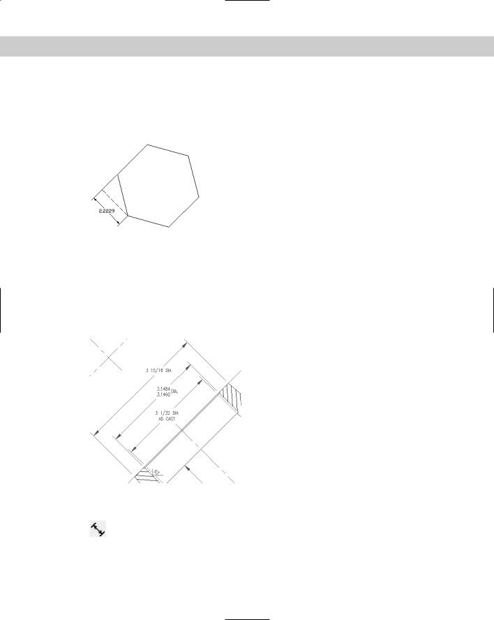
Figure 14-7 shows a hexagonal stepping-stone with a rotated linear angle. The extension lines of the dimension extend to a line at 104.5 degrees, but in this case you want to measure a length at an angle of 135 degrees. Note that the dimension really measures an imaginary line parallel to the dimension line, shown in the figure as a dashed line, rather than the side of the hexagon.
Figure 14-7: Drawing a rotated linear dimension for a hexagonal stepping stone.
Drawing Aligned Dimensions
When you want to dimension a linear object that is not orthogonal, use an aligned dimension. The dimension lines of an aligned dimension are always parallel to the object — unlike rotated dimensions. An aligned dimension measures the actual length of the object, not a vertical or horizontal distance that you dimension with a linear dimension. Therefore, your choice of linear, linear rotated, or aligned dimension depends on the distance you want to measure. Figure 14-8 shows several aligned dimensions.
Figure 14-8: Three aligned dimensions.
Specifying the dimensioned object
To create an aligned dimension, choose Aligned Dimension from the Dimension toolbar. This starts the DIMALIGNED command. The command responds with the Specify
first extension line origin or <select object>: prompt. As with linear dimensions, you can now either pick two extension line origins or press Enter to select an object.
Chapter 14 Drawing Dimensions 347
You then see the Specify dimension line location or [Mtext/Text/Angle]: prompt. Pick a point for the location of the dimension line. If you want an exact location, you can type in a relative coordinate, such as @2<45 to specify that the dimension line should be 2 units in a 45-degree direction from the extension line origins you specified.
Using the options
After you’ve chosen what you want to dimension, you have three options — MText, Text, and Angle. The previous section discusses these options in detail.
On the |
The drawing used in the following Step-by-Step exercise on drawing aligned dimensions, |
CD-ROM |
ab14-b.dwg, is in the Drawings folder on the CD-ROM. |
STEP-BY-STEP: Drawing Aligned Dimensions
1.Open ab14-b.dwg from your CD-ROM.
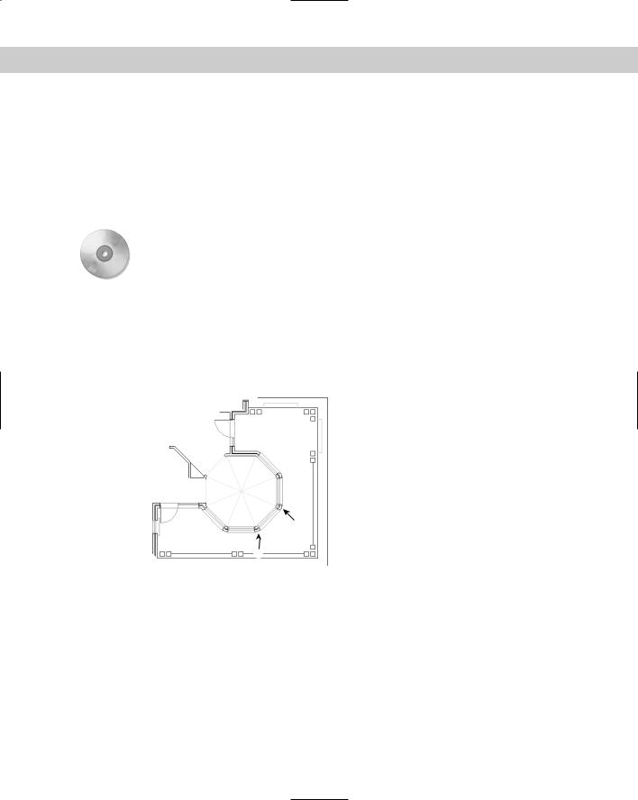
2.Save the file as ab14-02.dwg in your AutoCAD Bible folder. This is part of a floor plan of a house, as shown in Figure 14-9. OSNAP should be on. Set running object snaps to endpoint and intersection. If the Dimension toolbar isn’t visible, choose View Toolbars and check Dimension. Click Close.
Figure 14-9: A section of a floor plan of a house.
2
1
3. Choose Aligned Dimension from the Dimension toolbar. Follow the prompts:
Specify first extension line origin or <select object>: Choose 1 in Figure 14-9.
Specify second extension line origin: Choose 2 in Figure 14-9. Specify dimension line location or
[Mtext/Text/Angle]: Right-click and choose Mtext. In the Multiline Text Editor, move the cursor to the right of the angled brackets and type Typ. Click OK.
Specify dimension line location or
[Mtext/Text/Angle]: Pick a location for the dimension line.
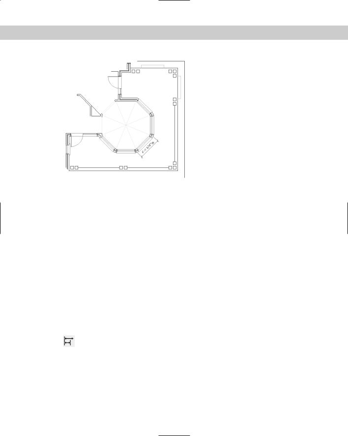
4.Save your drawing. It should look like Figure 14-10.
348 Part II Drawing in Two Dimensions
Figure 14-10: The house plan with an aligned dimension.
Creating Baseline and Continued Dimensions
Often, you want to create a whole series of attached, connected dimensions. You can accomplish this in two ways — baseline and continued dimensions:
Baseline dimensions are a series of dimensions that all start from one point. The first extension line is the same for all the dimensions. The second dimension includes the first dimension plus an additional distance and so on.
Continued dimensions are a series of dimensions that are all attached. The second dimension starts where the first dimension ends and so on. Each dimension measures a different object or distance.
Figure 14-11 shows both baseline and continued linear dimensions. You can also create baseline and continued angular and ordinate dimensions. Quick Dimension, covered later in this chapter, can quickly create baseline and continued linear dimensions. Here I cover the traditional method.
Drawing baseline dimensions
To draw a baseline dimension, first create one linear, angular, or ordinate dimension in the regular way. (Angular and ordinate dimensions are covered later in this chapter.)
Then choose Baseline Dimension from the Dimension toolbar. The command responds with the Specify a second extension line origin or [Undo/Select] <Select>: prompt.
If the previous dimension was a linear, angular, or ordinate dimension, the command uses the first extension line as the base for the new baseline dimension. Specify a new second extension line origin, and the command creates the baseline dimension with the same first extension origin as the original dimension and the new second extension origin you just specified.
Chapter 14 Drawing Dimensions 349
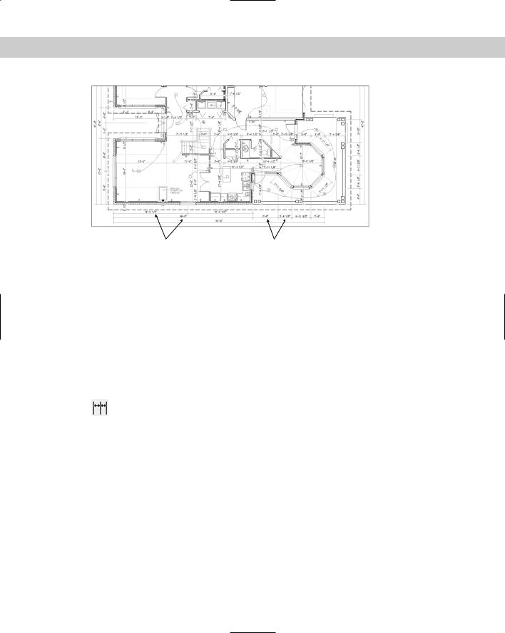
Baseline dimensions |
Continued dimensions |
Figure 14-11: A floor plan of a house using both baseline and continued dimensions.
If you don’t want to work with the previous dimension in the drawing, press Enter. The command responds with the Select base dimension: prompt. Be careful to pick the dimension closer to the side you want to use as the baseline. The command then prompts you to specify a second extension line origin. Doing so creates the dimension.
The command continues to prompt you for second extension line origins so that you can quickly create a chain of baseline dimensions. At each prompt, you can right-click and choose Undo to undo the previous dimension. You can also press Enter at any time and select a different dimension from which to work. Press Esc to end the command (or press Enter twice).
Drawing continued dimensions
Continued dimensions work similarly to baseline dimensions. To continue a dimension, first create one linear, angular, or ordinate dimension in the regular way. Then choose
Continue Dimension from the Dimension toolbar. The command responds with the Specify a second extension line origin or [Undo/ Select] <Select>: prompt.
If the previous dimension was a linear, angular, or ordinate dimension, the command uses the second extension line as the beginning of the new continued dimension. Specify a new second extension line origin to create the continued dimension.
If you don’t want to continue from the previous dimension in the drawing, press Enter. The command responds with the Select continued dimension: prompt. Be careful to pick the dimension closer to the side you want to continue from. You then get a prompt to specify a second extension line origin. Doing so creates the dimension.
The command continues to prompt you for second extension line origins so you can quickly create a chain of continued dimensions. At each prompt, you can right-click and choose Undo to undo the previous dimension. You can also press Enter at any time and select a different dimension to work from. Press Esc to end the command (or press Enter twice).
350 Part II Drawing in Two Dimensions
On the |
The drawing used in the following Step-by-Step exercise on drawing baseline and continued |
CD-ROM |
dimensions, ab14-b.dwg, is in the Drawings folder on the CD-ROM. |
STEP-BY-STEP: Drawing Baseline and Continued Dimensions
1.Open ab14-b.dwg from your CD-ROM.
2.Save the file as ab14-03.dwg in your AutoCAD Bible folder. This is the same drawing used in the previous two exercises, as shown in Figure 14-12. OSNAP should be on with running object snaps for endpoint and intersection. If the Dimension toolbar isn’t visible, right-click any toolbar and check Dimension.
3.Turn on ORTHO and OTRACK (if using AutoCAD) on the status bar.
4.Choose Linear Dimension from the Dimension toolbar. Follow the prompts:
Specify first extension line origin or <select object>: Pick the endpoint at 1 in Figure 14-12.
If you have AutoCAD, follow these prompts:
Specify second extension line origin: Pass the cursor over 3 to
acquire it for object snap tracking. Move the cursor to the right so that it’s vertically under 1 and click when you see the 1'-6”<0° tooltip.
If you have AutoCAD AutoCAD LT, follow these prompts:
Specify second extension line origin: Press Shift and right-click, then choose Point Filters .Y.
.Y of: Pick the endpoint at 3. (need XZ): Pick the endpoint 1.
For both AutoCAD and AutoCAD LT, continue with these prompts:
Specify dimension line location or [Mtext/Text/Angle/Horizontal/ Vertical/Rotated]: Pick a dimension line location to the right of the model.
5. Choose Continue Dimension from the Dimension toolbar.
For AutoCAD: At the Specify a second extension line origin or [Undo/ Select] <Select>: prompt, move the cursor over the endpoint or intersection at 4 to acquire it for object snap tracking. Move the cursor to the right, vertically below 1, and click when you see the tooltip.
For AutoCAD LT: At the Specify a second extension line origin or [Undo/ Select] <Select>: prompt, press Shift and right-click. Then choose Point Filters .Y. At the of .Y prompt, pick the endpoint at 4. At the (need XZ) prompt, pick the endpoint at 1.
This action places the continued dimension. Notice that the dimension uses a leader to place the text because there is not enough room between the extension lines. (If the
Chapter 14 Drawing Dimensions 351
leader is placed to the left, select it and pick the grip on the text. Pick a point to the right of the model and click to move the leader to the right.)
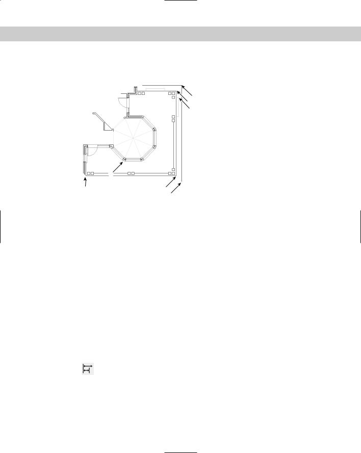
Figure 14-12: The house plan with the
1 octagonal ceiling.
3 4
|
7 |
5 |
6 |
|
2 |
6.The command repeats the Specify a second extension line origin or [Undo/ Select] <Select>: prompt. Pick the endpoint at 2 in Figure 14-12 to place the dimension. Press Enter twice to end the command.
7.Choose Linear Dimension from the Dimension toolbar. Follow the prompts:
Specify first extension line origin or <select object>: Choose the endpoint at 5 in Figure 14-12.
For AutoCAD, follow these prompts:
Specify second extension line origin: Move the cursor over 7 to
acquire it. Move the cursor down so that it’s horizontal to 5. When you see the 4'0"<270° tooltip, click.
For AutoCAD AutoCAD LT, follow these prompts:
Specify second extension line origin: Press Shift and right-click, then choose Point Filters .X. At the of .X prompt, pick the endpoint at 7. At the (need YZ) prompt pick the endpoint at 5.
For both AutoCAD and AutoCAD LT, continue with these prompts:
Specify dimension line location or [Mtext/Text/Angle/Horizontal/ Vertical/Rotated]: Pick a dimension line location fairly close to the line you dimensioned leaving just enough room for the dimension text.
8.Choose Baseline Dimension from the Dimension toolbar. At the Specify a second extension line origin or [Undo/Select] <Select>: prompt,
pick the endpoint or intersection at 6 in Figure 14-12. Press Enter twice to end the command.
9. Save your drawing. It should look like Figure 14-13.