

- •Foreword
- •Preface
- •Is This Book for You?
- •How This Book Is Organized
- •How to Use This Book
- •Doing the Exercises
- •Conventions Used in This Book
- •What the Icons Mean
- •About the CD-ROM
- •Other Information
- •Contacting the Author
- •Acknowledgments
- •Contents at a Glance
- •Contents
- •Getting Acquainted with AutoCAD and AutoCAD LT
- •Starting AutoCAD and AutoCAD LT
- •Creating a New Drawing
- •Using the AutoCAD and AutoCAD LT Interface
- •Creating Your First Drawing
- •Saving a Drawing
- •Summary
- •Creating a New Drawing from a Template
- •Working with Templates
- •Opening a Drawing with Default Settings
- •Opening an Existing Drawing
- •Using an Existing Drawing as a Prototype
- •Saving a Drawing Under a New Name
- •Summary
- •The Command Line
- •Command Techniques
- •Of Mice and Pucks
- •Getting Help
- •Summary
- •Typing Coordinates
- •Displaying Coordinates
- •Picking Coordinates on the Screen
- •Locating Points
- •Summary
- •Unit Types
- •Drawing Limits
- •Understanding Scales
- •Inserting a Title Block
- •Common Setup Options
- •The MVSETUP Command
- •Summary
- •Using the LINE Command
- •Drawing Rectangles
- •Drawing Polygons
- •Creating Construction Lines
- •Creating Rays
- •Summary
- •Drawing Circles
- •Drawing Arcs
- •Creating Ellipses and Elliptical Arcs
- •Making Donuts
- •Placing Points
- •Summary
- •Panning
- •The ZOOM Command
- •Aerial View
- •Named Views
- •Tiled Viewports
- •Snap Rotation
- •User Coordinate Systems
- •Isometric Drawing
- •Summary
- •Editing a Drawing
- •Selecting Objects
- •Summary
- •Copying and Moving Objects
- •Using Construction Commands
- •Creating a Revision Cloud
- •Hiding Objects with a Wipeout
- •Double-Clicking to Edit Objects
- •Grips
- •Editing with the Properties Palette
- •Selection Filters
- •Groups
- •Summary
- •Working with Layers
- •Changing Object Color, Linetype, and Lineweight
- •Working with Linetype Scales
- •Importing Layers and Linetypes from Other Drawings
- •Matching Properties
- •Summary
- •Drawing-Level Information
- •Object-Level Information
- •Measurement Commands
- •AutoCAD’s Calculator
- •Summary
- •Creating Single-Line Text
- •Understanding Text Styles
- •Creating Multiline Text
- •Creating Tables
- •Inserting Fields
- •Managing Text
- •Finding Text in Your Drawing
- •Checking Your Spelling
- •Summary
- •Working with Dimensions
- •Drawing Linear Dimensions
- •Drawing Aligned Dimensions
- •Creating Baseline and Continued Dimensions
- •Dimensioning Arcs and Circles
- •Dimensioning Angles
- •Creating Ordinate Dimensions
- •Drawing Leaders
- •Using Quick Dimension
- •Editing Dimensions
- •Summary
- •Understanding Dimension Styles
- •Defining a New Dimension Style
- •Changing Dimension Styles
- •Creating Geometric Tolerances
- •Summary
- •Creating and Editing Polylines
- •Drawing and Editing Splines
- •Creating Regions
- •Creating Boundaries
- •Creating Hatches
- •Creating and Editing Multilines
- •Creating Dlines
- •Using the SKETCH Command
- •Digitizing Drawings with the TABLET Command
- •Summary
- •Preparing a Drawing for Plotting or Printing
- •Creating a Layout in Paper Space
- •Working with Plot Styles
- •Plotting a Drawing
- •Summary
- •Combining Objects into Blocks
- •Inserting Blocks and Files into Drawings
- •Managing Blocks
- •Using Windows Features
- •Working with Attributes
- •Summary
- •Understanding External References
- •Editing an Xref within Your Drawing
- •Controlling Xref Display
- •Managing Xrefs
- •Summary
- •Preparing for Database Connectivity
- •Connecting to Your Database
- •Linking Data to Drawing Objects
- •Creating Labels
- •Querying with the Query Editor
- •Working with Query Files
- •Summary
- •Working with 3D Coordinates
- •Using Elevation and Thickness
- •Working with the User Coordinate System
- •Summary
- •Working with the Standard Viewpoints
- •Using DDVPOINT
- •Working with the Tripod and Compass
- •Getting a Quick Plan View
- •Shading Your Drawing
- •Using 3D Orbit
- •Using Tiled Viewports
- •Defining a Perspective View
- •Laying Out 3D Drawings
- •Summary
- •Drawing Surfaces with 3DFACE
- •Drawing Surfaces with PFACE
- •Creating Polygon Meshes with 3DMESH
- •Drawing Standard 3D Shapes
- •Drawing a Revolved Surface
- •Drawing an Extruded Surface
- •Drawing Ruled Surfaces
- •Drawing Edge Surfaces
- •Summary
- •Drawing Standard Shapes
- •Creating Extruded Solids
- •Drawing Revolved Solids
- •Creating Complex Solids
- •Sectioning and Slicing Solids
- •Using Editing Commands in 3D
- •Editing Solids
- •Listing Solid Properties
- •Summary
- •Understanding Rendering
- •Creating Lights
- •Creating Scenes
- •Working with Materials
- •Using Backgrounds
- •Doing the Final Render
- •Summary
- •Accessing Drawing Components with the DesignCenter
- •Accessing Drawing Content with Tool Palettes
- •Setting Standards for Drawings
- •Organizing Your Drawings
- •Working with Sheet Sets
- •Maintaining Security
- •Keeping Track of Referenced Files
- •Handling Errors and Crashes
- •Managing Drawings from Prior Releases
- •Summary
- •Importing and Exporting Other File Formats
- •Working with Raster Images
- •Pasting, Linking, and Embedding Objects
- •Summary
- •Sending Drawings
- •Opening Drawings from the Web
- •Creating Object Hyperlinks
- •Publishing Drawings
- •Summary
- •Working with Customizable Files
- •Creating Keyboard Shortcuts for Commands
- •Customizing Toolbars
- •Customizing Tool Palettes
- •Summary
- •Creating Macros with Script Files
- •Creating Slide Shows
- •Creating Slide Libraries
- •Summary
- •Creating Linetypes
- •Creating Hatch Patterns
- •Summary
- •Creating Shapes
- •Creating Fonts
- •Summary
- •Working with Menu Files
- •Customizing a Menu
- •Summary
- •Introducing Visual LISP
- •Getting Help in Visual LISP
- •Working with AutoLISP Expressions
- •Using AutoLISP on the Command Line
- •Creating AutoLISP Files
- •Summary
- •Creating Variables
- •Working with AutoCAD Commands
- •Working with Lists
- •Setting Conditions
- •Managing Drawing Objects
- •Getting Input from the User
- •Putting on the Finishing Touches
- •Summary
- •Understanding Local and Global Variables
- •Working with Visual LISP ActiveX Functions
- •Debugging Code
- •Summary
- •Starting to Work with VBA
- •Writing VBA Code
- •Getting User Input
- •Creating Dialog Boxes
- •Modifying Objects
- •Debugging and Trapping Errors
- •Moving to Advanced Programming
- •A Final Word
- •Installing AutoCAD and AutoCAD LT
- •Configuring AutoCAD
- •Starting AutoCAD Your Way
- •Configuring a Plotter
- •System Requirements
- •Using the CD with Microsoft Windows
- •What’s on the CD
- •Troubleshooting
- •Index

542 Part III Working with Data
11.Choose External Reference from the Reference toolbar. In the Xref Manager dialog box, select ab19-04.dwg and click Detach. (Detaching xrefs is covered later in this chapter.) Click OK. You can now see that ab19-03.dwg includes the North symbol and letter because they were removed from the xref.
12.To see the results of the editing on the xref, open ab19-04.dwg. You can see the changes in the title block text and that the North symbol and letter are gone.
13.Close both drawings, saving changes to ab19-03.dwg.
Controlling Xref Display
You can control the display of xref layers so that you see only those layers you need. Several features let you control the process of displaying xrefs, making it easier to see only part of an xref and speeding up the display of very large xrefs.
Xrefs and dependent symbols
Dependent symbols are named items in a drawing, such as layers, text styles, dimension styles, and so on. When you attach an xref, these symbols are listed in your current drawing. For example, the Layer Control drop-down list displays the layers of the xref. Xref symbols have the format xref_name|symbol_name. This system distinguishes xref symbols from those of your current drawing and ensures that there are no duplicate symbols.
Xrefs and layers
You can turn on and off, or freeze and thaw, xref layers. You can also change an xref layer’s properties in the Layer Properties Manager dialog box. By default, these changes are retained. However, you can set the VISRETAIN system variable to 0 to discard these changes. The next time you open the drawing or reload the xref, the original settings are restored.
Objects created on layer 0 do not take on the typical xref layer name format, but stay on layer 0. If objects in the xref are on layer 0 with the color and linetype set to ByLayer, they take on the color and linetype properties of the current layer in the current drawing. If color and linetype are set to ByBlock, objects assume the current properties when the xref is attached. If you explicitly set color and linetype, objects retain those settings.
The XBIND command
You can use the XBIND command to import only the symbols you want from the external reference into the current drawing. This makes it easy to work with a consistent set of symbols in the current drawing and the xrefs. For example, you can choose to import the titleblk layer and the dec dimension style. Type xbind on the command line. The Xbind dialog box opens, listing each xref in the drawing and its symbols in a Windows Explorer–like display, as shown in Figure 19-8.
Click the plus sign next to any symbol type to open a list of symbols. Click the one you want and choose Add to add it to the Definitions to Bind list. Click OK when you’re done.
Later in this chapter, I explain how you can use the DesignCenter to move xrefs and other dependent symbols from one drawing to another.

Chapter 19 Referencing Other Drawings 543
Figure 19-8: Using the XBIND command to import symbols, such as layers, text styles, and so on.
Circular references
If drawing a includes drawing b as an xref and drawing b includes drawing a as an xref, you have a circular reference. Circular references can exist among three or more xrefs when you have nested xrefs. The program detects circular references and loads as much as it can. If you try to load an xref in such a situation, you see the following message:
Warning: Circular reference from XREF to current |
drawing. |
Circular reference(s) have been found. Continue? |
<N> Type y to continue |
to load the xref. |
|
Breaking circular reference from XREF to current |
drawing. |
Clipping xrefs
You may want to see only part of an xref. This option is especially important when you’re using very large xref drawings. The XCLIP command enables you to create a border in an xref and hides any part of the xref outside the border.
AutoCAD LT doesn’t include the xref clipping feature.
To clip an xref, choose Modify Clip Xref or choose External Reference Clip from the Reference toolbar. At the prompt to select objects, pick the xref you want to clip. Note
that any nested xrefs are clipped with the main xref you select.
Table 19-1 explains the options of this command.

544 Part III Working with Data
|
|
Table 19-1: XCLIP Options |
|
|
|
|
Option |
How to Use It |
|
|
|
|
ON |
Turns the clipping boundary on, displaying only the portion of the xref inside |
|
|
the clipping boundary. By default, the clipping boundary is on. Use this after |
|
|
you’ve turned it off to see only the clipped portion again. |
|
OFF |
Turns the clipping boundary off, displaying the entire xref. The clipping |
|
|
boundary is still retained. This is somewhat like turning off a layer. You may |
|
|
want to see the entire xref for a while (for example, while redefining the |
|
|
boundary). Then you can turn the boundary back on (using the ON option) |
|
|
when you need only the clipped portion again. |
|
Clipdepth |
This is used for 3D drawings only. After you set a clipping boundary, you can set |
|
|
front and back planes parallel to the boundary to display only the portion of the |
|
|
xref within that three-dimensional space. You create the front and back planes |
|
|
by specifying a distance from the clipping boundary. The Remove suboption |
|
|
removes the clipping planes. |
|
Delete |
Deletes the clipping boundary. The boundary is no longer retained in the |
|
|
drawing. |
|
Generate polyline |
Creates a polyline from the clipping boundary, using the current layer, color, and |
|
|
linetype. If you want to change the clipping boundary, you can edit the polyline |
|
|
by using PEDIT and redefine the boundary with the new polyline. |
|
New boundary |
This is the default option. Press Enter to get the suboptions. |
|
Select polyline |
Enables you to specify the clipping boundary by selecting an existing polyline. |
|
|
This option decurves fit-curved or arc portions of the polyline when creating the |
|
|
boundary. |
|
Polygonal |
Enables you to specify a polygonal area — such as a polyline with straight edges. |
|
|
This option creates a rubber-band line as you pick points, keeping the polygon |
|
|
closed. You can use this option to create an irregularly shaped area that includes |
|
|
only the portion of the xref you wish to see. |
|
Rectangular |
Enables you to pick two points on diagonally opposite corners of a rectangle, |
|
|
such as creating a selection window. |
|
|
|
Tip |
You can also clip blocks. |
|
|
To see the clipping boundary (if you haven’t used an existing polyline to define it), change |
|
|
the value of the XCLIPFRAME system variable to 1. |
|
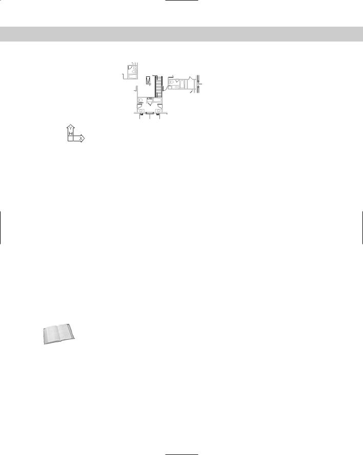
Figure 19-9 shows an xref clipped with a polygonal boundary. Compare this to Figure 19-4, which shows the entire xref.
Chapter 19 Referencing Other Drawings 545
Figure 19-9: An xref clipped with a polygonal boundary.
Speeding up the display of large xrefs
In order to reduce the time needed to display large xrefs, such as those used in GIS or 3D drawings, you can use demand loading, which enables you to load only the objects necessary to display the xref in your drawing. Demand loading works together with spatial and layer indexes.
The spatial index is created when you save a drawing. This index is used when you have enabled demand loading and attach a clipped xref that was saved with a spatial index. The index determines how much of the xref needs to be read to display it.
The layer index is also created when you save a drawing. This index is used when you’ve enabled demand loading and attach an xref that was saved with a layer index and has frozen or turned off layers. The index determines how much of the xref needs to be read to display it.
To make it perfectly clear, you need all the following to use this demand loading:
Demand loading must be enabled in the current drawing.
The xref must have been saved with a spatial or layer index.
The xref must either be clipped (for a spatial index) or have layers that are frozen or turned off (for a layer index).
Cross- |
Demand loading is similar to partial opening and loading of drawings, explained in Chapter 8. |
Reference |
|
Demand loading
You turn on demand loading in your current drawing. To turn on demand loading, choose Tools Options, and then click the Open and Save tab. In the Demand Load Xrefs drop-down list, choose Enabled. Others on a networked system cannot then edit the original drawing while you’re referencing it. To let others edit the original drawing, choose Enabled with Copy. This option uses a copy of the referenced drawing for your xref. Click OK. You can turn on demand loading just before you attach an xref. You don’t need to keep demand loading on all the time.
546 Part III Working with Data
Spatial indexes
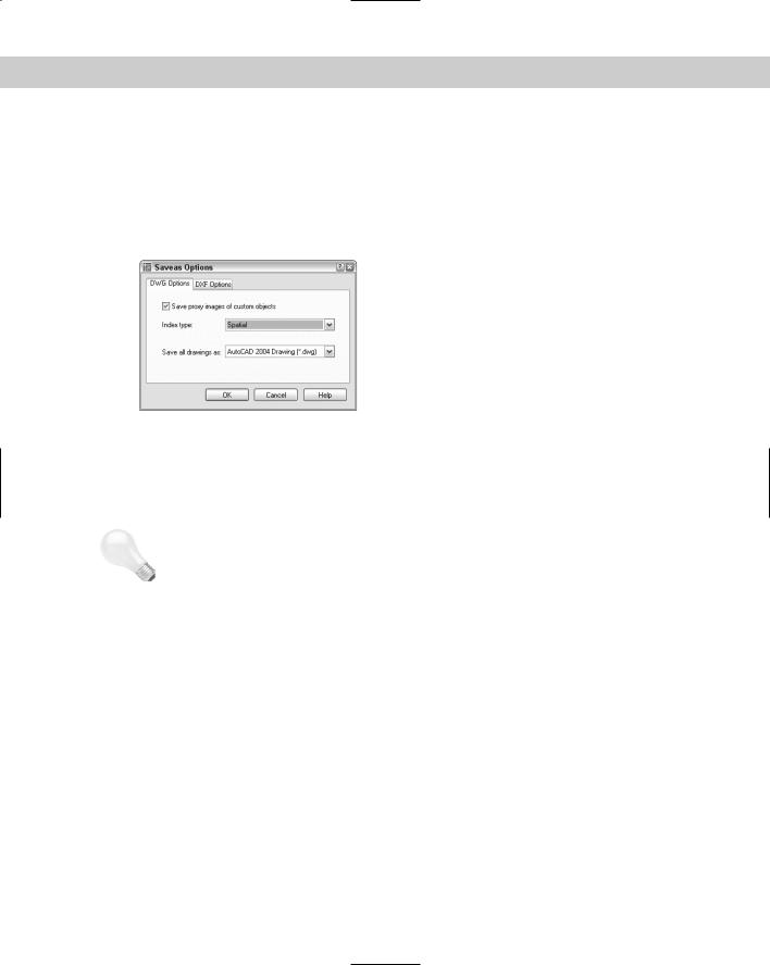
You save a spatial index for a drawing that you expect to use as an xref. The saving process takes a little longer, but you save time at the other end when you load a clipped xref or clip an xref for the first time. To create a spatial index in AutoCAD, choose File Save As to open the Save Drawing As dialog box. From the Tools menu at the top-right of the dialog box, choose Options to open the Saveas Options dialog box, shown in Figure 19-10 with the DWG Options tab on top.
|
Figure 19-10: The DWG Options tab of |
|
the Saveas Options dialog box. |
|
From the Index Type drop-down list, choose Spatial or Layer & Spatial. Click OK. Then click |
|
Save in the Save Drawing As dialog box. In AutoCAD LT, use the INDEXCTL system variable |
|
on the command line and set its value to 2 for just a spatial index or to 3 for both spatial and |
|
layer indexes. |
Tip |
If you want to create an index for an existing drawing, click OK once to return to the Save |
|
Drawing As dialog box. Click Cancel. In other words, you don’t have to actually save the draw- |
|
ing to set up the index, which is controlled by the INDEXCTL system variable. |
|
After you create a spatial index, each time you save the drawing you see the following |
|
message: |
|
Updating Indexes for block *MODEL_SPACE |
|
To stop saving the index each time you save, choose File Save As. Choose Tools Options. |
|
In the Saveas Options dialog box, choose None from the Index Type drop-down list. Click OK |
|
and then click Cancel. |
|
Layer indexes |
|
You save a layer index for a drawing that you expect to use as an xref to create an index of all |
|
the layers in the drawing. As with a spatial index, the saving process takes a little longer, but |
|
you save time at the other end when you load an xref with frozen or turned off layers. To cre- |
|
ate a layer index in AutoCAD, choose File Save As to open the Save Drawing As dialog box. |
|
From the Tools menu at the upper-right corner of the dialog box, choose Options to open the |
|
Saveas Options dialog box, shown in Figure 19-10. |

Chapter 19 Referencing Other Drawings 547
From the Index Type drop-down list, choose Layer or Layer & Spatial. Click OK, and then click Cancel. In AutoCAD LT, set the INDEXCTL system variable to 1 for just a layer index or 3 for both layer and spatial indexes.
After you create a layer index, each time you save the drawing you see the following message:
Updating Indexes for block *MODEL_SPACE
To stop saving the index, choose File Save As. Choose Options. In the Saveas Options dialog box, choose None from the Index Type drop-down list. Click OK once and then click Cancel.
On the |
The drawings used in the following Step-by-Step exercise on controlling xref display — ab19-a. |
CD-ROM |
dwg, ab19-b.dwg, ab19-01.dwg, and ab19-02.dwg — are in the Drawings and Results |
|
folders on the CD-ROM. |
STEP-BY-STEP: Controlling Xref Display
1.Open ab19-01.dwg from your AutoCAD Bible folder if you did the first exercise in this chapter.
If you didn’t do the first exercise in this chapter, use Windows Explorer to find ab19-b. dwg in the Drawings folder on the CD-ROM and ab19-01.dwg and ab19-02.dwg in the
Results folder on the CD-ROM. Copy all three files to your AutoCAD Bible folder. In Windows Explorer, right-click each file and choose Properties. Uncheck the Read-Only option (if checked) and click OK. Then open ab19-01.dwg from your AutoCAD Bible folder. If you get a message that the drawing cannot find the xrefs, choose Tools Options and click Project Files Search Path on the Files tab. Click Add and add your AutoCAD Bible folder. You can click Browse to choose the folder from a dialog box.
2.To create layer and spatial indexes, do one of the following:
•If you have AutoCAD: Choose File Save As. From the Tools menu of the dialog box, choose Options. In the Index Type drop-down list of the Saveas Options dialog box, choose Layer & Spatial. Click OK. (It may already be set for these indexes.) Click Cancel.
•If you have AutoCAD LT: On the command line, enter indexctl . Then enter 3 .
3.Choose Save from the Standard toolbar. Note the message on the command line that the indexes are being updated.
4.Close ab19-01.dwg.
5.Open ab19-02.dwg from your AutoCAD Bible folder. This drawing has an attached xref of a house plan and a nested xref of a title block, as shown in Figure 19-11.
6.Save it as ab19-05.dwg in your AutoCAD Bible folder.
7.Choose Tools Options and click the Open and Save tab. In the Demand Load Xrefs drop-down list, choose Enabled. (It may already be set to Enabled.) Click OK.
8.Click the Layer Control drop-down list. Click the On/Off icon next to the Ab19-01|notes layer to turn the layer back on. Click the top of the drop-down list box to close it. The notes layer displays.

548 Part III Working with Data
1
|
2 |
|
0 |
3 |
4 |
|
9
6 5
8 7
Figure 19-11: Picking a polygonal boundary to clip an xref.
9.In AutoCAD only, choose External Reference Clip from the Reference toolbar or choose Modify Clip Xref to start the XCLIP command. (If you have AutoCAD LT,
skip this step.) Follow the prompts:
Select objects: Pick anywhere on the xref in Figure 19-11.
Select objects: Enter clipping option
[ON/OFF/Clipdepth/Delete/generate Polyline/New boundary] <New>: Specify clipping boundary:
[Select polyline/Polygonal/Rectangular] <Rectangular>: Right-click and choose Polygonal.
Specify first point: Pick 1 in Figure 19-11. It might help to turn
off OSNAP if it is on. |
|
Specify next point or |
[Undo]: Pick 2. |
Specify next point or |
[Undo]: Pick 3. |
Specify next point or |
[Undo]: Pick 4. |
Specify next point or |
[Undo]: Pick 5. |
Specify next point or |
[Undo]: Pick 6. |
Specify next point or |
[Undo]: Pick 7. |
Specify next point or |
[Undo]: Pick 8. |
Specify next point or |
[Undo]: Pick 9. |
Specify next point or |
[Undo]: Pick 0. |
Specify next point or |
[Undo]: |
This action clips the xref. |
|
10.Turn off the Ab19-01|notes layer again.
11.Save your drawing. It should look like Figure 19-12. (If you have AutoCAD LT, you still see the entire xref.) Keep the drawing open if you’re continuing on to the next exercise.