

- •Foreword
- •Preface
- •Is This Book for You?
- •How This Book Is Organized
- •How to Use This Book
- •Doing the Exercises
- •Conventions Used in This Book
- •What the Icons Mean
- •About the CD-ROM
- •Other Information
- •Contacting the Author
- •Acknowledgments
- •Contents at a Glance
- •Contents
- •Getting Acquainted with AutoCAD and AutoCAD LT
- •Starting AutoCAD and AutoCAD LT
- •Creating a New Drawing
- •Using the AutoCAD and AutoCAD LT Interface
- •Creating Your First Drawing
- •Saving a Drawing
- •Summary
- •Creating a New Drawing from a Template
- •Working with Templates
- •Opening a Drawing with Default Settings
- •Opening an Existing Drawing
- •Using an Existing Drawing as a Prototype
- •Saving a Drawing Under a New Name
- •Summary
- •The Command Line
- •Command Techniques
- •Of Mice and Pucks
- •Getting Help
- •Summary
- •Typing Coordinates
- •Displaying Coordinates
- •Picking Coordinates on the Screen
- •Locating Points
- •Summary
- •Unit Types
- •Drawing Limits
- •Understanding Scales
- •Inserting a Title Block
- •Common Setup Options
- •The MVSETUP Command
- •Summary
- •Using the LINE Command
- •Drawing Rectangles
- •Drawing Polygons
- •Creating Construction Lines
- •Creating Rays
- •Summary
- •Drawing Circles
- •Drawing Arcs
- •Creating Ellipses and Elliptical Arcs
- •Making Donuts
- •Placing Points
- •Summary
- •Panning
- •The ZOOM Command
- •Aerial View
- •Named Views
- •Tiled Viewports
- •Snap Rotation
- •User Coordinate Systems
- •Isometric Drawing
- •Summary
- •Editing a Drawing
- •Selecting Objects
- •Summary
- •Copying and Moving Objects
- •Using Construction Commands
- •Creating a Revision Cloud
- •Hiding Objects with a Wipeout
- •Double-Clicking to Edit Objects
- •Grips
- •Editing with the Properties Palette
- •Selection Filters
- •Groups
- •Summary
- •Working with Layers
- •Changing Object Color, Linetype, and Lineweight
- •Working with Linetype Scales
- •Importing Layers and Linetypes from Other Drawings
- •Matching Properties
- •Summary
- •Drawing-Level Information
- •Object-Level Information
- •Measurement Commands
- •AutoCAD’s Calculator
- •Summary
- •Creating Single-Line Text
- •Understanding Text Styles
- •Creating Multiline Text
- •Creating Tables
- •Inserting Fields
- •Managing Text
- •Finding Text in Your Drawing
- •Checking Your Spelling
- •Summary
- •Working with Dimensions
- •Drawing Linear Dimensions
- •Drawing Aligned Dimensions
- •Creating Baseline and Continued Dimensions
- •Dimensioning Arcs and Circles
- •Dimensioning Angles
- •Creating Ordinate Dimensions
- •Drawing Leaders
- •Using Quick Dimension
- •Editing Dimensions
- •Summary
- •Understanding Dimension Styles
- •Defining a New Dimension Style
- •Changing Dimension Styles
- •Creating Geometric Tolerances
- •Summary
- •Creating and Editing Polylines
- •Drawing and Editing Splines
- •Creating Regions
- •Creating Boundaries
- •Creating Hatches
- •Creating and Editing Multilines
- •Creating Dlines
- •Using the SKETCH Command
- •Digitizing Drawings with the TABLET Command
- •Summary
- •Preparing a Drawing for Plotting or Printing
- •Creating a Layout in Paper Space
- •Working with Plot Styles
- •Plotting a Drawing
- •Summary
- •Combining Objects into Blocks
- •Inserting Blocks and Files into Drawings
- •Managing Blocks
- •Using Windows Features
- •Working with Attributes
- •Summary
- •Understanding External References
- •Editing an Xref within Your Drawing
- •Controlling Xref Display
- •Managing Xrefs
- •Summary
- •Preparing for Database Connectivity
- •Connecting to Your Database
- •Linking Data to Drawing Objects
- •Creating Labels
- •Querying with the Query Editor
- •Working with Query Files
- •Summary
- •Working with 3D Coordinates
- •Using Elevation and Thickness
- •Working with the User Coordinate System
- •Summary
- •Working with the Standard Viewpoints
- •Using DDVPOINT
- •Working with the Tripod and Compass
- •Getting a Quick Plan View
- •Shading Your Drawing
- •Using 3D Orbit
- •Using Tiled Viewports
- •Defining a Perspective View
- •Laying Out 3D Drawings
- •Summary
- •Drawing Surfaces with 3DFACE
- •Drawing Surfaces with PFACE
- •Creating Polygon Meshes with 3DMESH
- •Drawing Standard 3D Shapes
- •Drawing a Revolved Surface
- •Drawing an Extruded Surface
- •Drawing Ruled Surfaces
- •Drawing Edge Surfaces
- •Summary
- •Drawing Standard Shapes
- •Creating Extruded Solids
- •Drawing Revolved Solids
- •Creating Complex Solids
- •Sectioning and Slicing Solids
- •Using Editing Commands in 3D
- •Editing Solids
- •Listing Solid Properties
- •Summary
- •Understanding Rendering
- •Creating Lights
- •Creating Scenes
- •Working with Materials
- •Using Backgrounds
- •Doing the Final Render
- •Summary
- •Accessing Drawing Components with the DesignCenter
- •Accessing Drawing Content with Tool Palettes
- •Setting Standards for Drawings
- •Organizing Your Drawings
- •Working with Sheet Sets
- •Maintaining Security
- •Keeping Track of Referenced Files
- •Handling Errors and Crashes
- •Managing Drawings from Prior Releases
- •Summary
- •Importing and Exporting Other File Formats
- •Working with Raster Images
- •Pasting, Linking, and Embedding Objects
- •Summary
- •Sending Drawings
- •Opening Drawings from the Web
- •Creating Object Hyperlinks
- •Publishing Drawings
- •Summary
- •Working with Customizable Files
- •Creating Keyboard Shortcuts for Commands
- •Customizing Toolbars
- •Customizing Tool Palettes
- •Summary
- •Creating Macros with Script Files
- •Creating Slide Shows
- •Creating Slide Libraries
- •Summary
- •Creating Linetypes
- •Creating Hatch Patterns
- •Summary
- •Creating Shapes
- •Creating Fonts
- •Summary
- •Working with Menu Files
- •Customizing a Menu
- •Summary
- •Introducing Visual LISP
- •Getting Help in Visual LISP
- •Working with AutoLISP Expressions
- •Using AutoLISP on the Command Line
- •Creating AutoLISP Files
- •Summary
- •Creating Variables
- •Working with AutoCAD Commands
- •Working with Lists
- •Setting Conditions
- •Managing Drawing Objects
- •Getting Input from the User
- •Putting on the Finishing Touches
- •Summary
- •Understanding Local and Global Variables
- •Working with Visual LISP ActiveX Functions
- •Debugging Code
- •Summary
- •Starting to Work with VBA
- •Writing VBA Code
- •Getting User Input
- •Creating Dialog Boxes
- •Modifying Objects
- •Debugging and Trapping Errors
- •Moving to Advanced Programming
- •A Final Word
- •Installing AutoCAD and AutoCAD LT
- •Configuring AutoCAD
- •Starting AutoCAD Your Way
- •Configuring a Plotter
- •System Requirements
- •Using the CD with Microsoft Windows
- •What’s on the CD
- •Troubleshooting
- •Index
Chapter 31 Creating Your Own Linetypes and Hatch Patterns 931
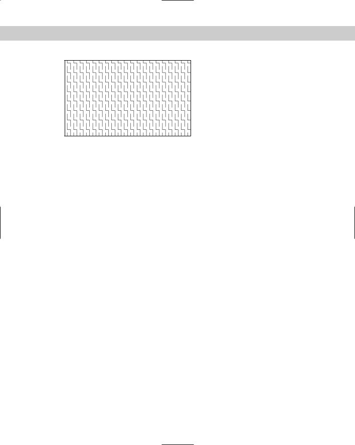
Figure 31-11: The lightning hatch pattern.
Check out the acad.pat or aclt.pat file for some ideas on how to create your own hatchpattern definitions.
Summary
In this chapter, you discovered how to create your own linetypes and hatch patterns. You read about the following:
Creating simple linetypes containing only dashes, dots, and spaces
Making complex linetypes that include shapes and text
Constructing your own hatch patterns that are made up of a set of parallel lines In the next chapter, you read about how to create shapes and fonts.

Creating Shapes
and Fonts
Shapes are similar to blocks. You create them, store them, and insert them.
AutoCAD LT doesn’t offer the shape feature. This entire chapter applies to AutoCAD only.
There are several differences between shapes and blocks:
Shapes are much harder to create.
Shapes are compiled into a format that conserves storage space, memory, and regeneration time.
You can use shapes to create fonts.
Font and shape files are support files — if you distribute
a drawing, be sure to include any font or shape files that the drawing uses.
You can use shapes for simple forms that you need to insert many times quickly. Examples are shapes inserted into complex linetypes and font characters.
Creating Shapes
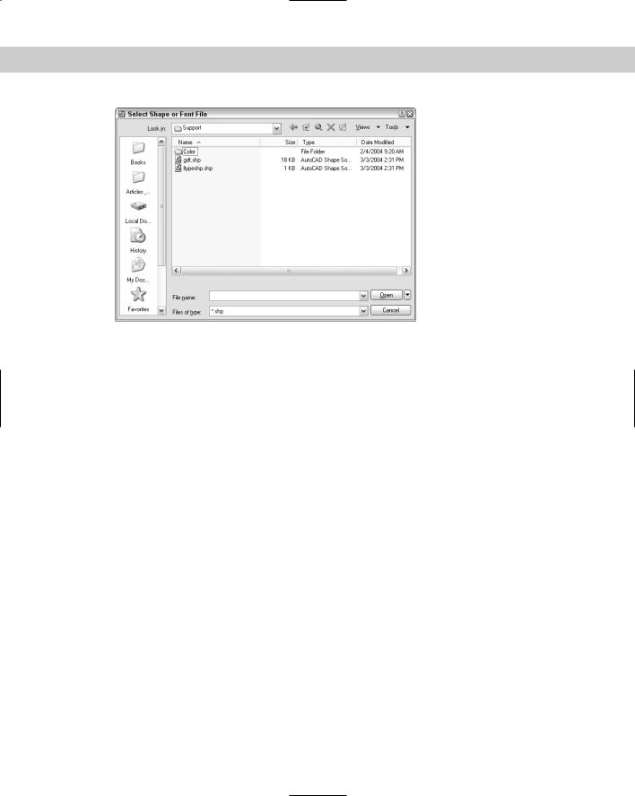
Shape files are used for both shapes and fonts. You create them with a text editor and save them with the extension .shp. You then use the COMPILE command (on the command line), which opens the Select Shape or Font File dialog box, shown in Figure 32-1.
Choose the .shp file and click Open. AutoCAD automatically compiles the file into a new file with the same name but with an extension of
.shx, and displays a message on the command line that compilation succeeded.
32C H A P T E R
In This Chapter
Creating shapes
Creating fonts
934 Part VI Customizing AutoCAD
Figure 32-1: The Select Shape or Font File dialog box.
Using shape files
After you have a compiled shape file, you must load it with the LOAD command before you can place it in a drawing. The Select Shape File dialog box opens. Choose the .shx file and click Open. Font files don’t have to be loaded because they’re automatically referenced by text styles that use the font files.
To insert a shape, use the SHAPE command prompts as follows:
1.Enter shape name or [?]: Type the name of the shape or type ? to get a list of loaded shapes.
2.Specify insertion point: Pick a point on the screen. AutoCAD drags the shape as you move the cursor.
3.Specify height <1.0000>: This functions like a scale factor. For example, type
.5 to insert the shape at one-half its original size.
4.Specify rotation angle <0>: Type a rotation angle.
Creating shape files
Shape files and font files are essentially the same. In this section, I explain how to create shapes. At the end of the chapter, I explain the few distinctions necessary to create a font file.
As with most customizable files, you use a text editor to create shape files. You can add comments following a semicolon. A shape definition has the following syntax:
*shapenumber,#ofspecs,SHAPENAME spec1,spec2,...,0
The definition must start with an asterisk. Each line cannot contain more than 128 characters. Table 32-1 explains the parts of this shape definition.

Chapter 32 Creating Shapes and Fonts 935
|
Table 32-1: The Parts of a Shape Definition |
|
|
Item |
Explanation |
|
|
shapenumber |
You can use any number from 1 to 255. Each shape in a file must have a unique |
|
number. |
#ofspecs |
This is the number of specifications in the second line of the definition, including |
|
the mandatory 0 at the end. |
SHAPENAME |
You must use uppercase for the shape name. This is the name you use with the |
|
SHAPE command. |
spec1... |
This is a code that defines the actual shape. Each specification code defines a |
|
part of the shape, such as a line segment or an arc. Together, all the specifications |
|
draw the shape. |
0 |
The definition must end with a 0. |
|
|
Length and direction codes
You can use two sets of codes to define a shape. The first set — the length and direction codes — only lets you draw straight line segments. You use this system to create specifications in the three-character hexadecimal format.
The first character is 0, which tells AutoCAD that the next two characters are hexadecimal values.
The second character is a length in units. The maximum is 15 units. The number values can range from 0 to 9. For values from 10 to 15, use A to F. However, the length is measured along the nearest X or Y distance. Therefore, diagonal lengths are not true lengths.
The third character is a direction code. Figure 32-2 shows how this code works. Use the code that represents the desired direction of the line from the start point.
Figure 32-2: The direction codes.
Here is the code for the shape shown in Figure 32-3:
*2,4,PENNANT
044,02F,029,0

936 Part VI Customizing AutoCAD
Figure 32-3: The PENNANT shape.
Here’s how this shape works:
2 is the shape’s unique number.
4 is the number of bytes (specifications) on the second line of the definition.
PENNANT is the shape’s name.
044 draws the pole, a line that is 4 units in the vertical direction.
02F draws the top line of the pennant, a line that is approximately 2 units in the F direction. (See the following note.)
029 draws the bottom line of the pennant, a line that is approximately 2 units in the 9 direction. (See the following note.)
Note |
Although the length of the two diagonal lines was specified as 2, they’re actually about 2.22 |
|
units long because the line endpoints snapped to the nearest imaginary grid point. |
Supplemental codes
The length and direction codes have a number of limitations:
You can draw in only 16 directions.
The maximum length of a line is 15 units.
You can only draw straight line segments.
The shape has to be continuous — you cannot lift the “pen” up and start in a new place.
The second set of codes, the supplemental codes, brings additional flexibility (and complexity) to your shapes. Table 32-2 lists these codes, which can be in either hexadecimal or decimal format.
Table 32-2: Supplemental Shape Codes
Hexadecimal Code |
Decimal Code |
Explanation |
|
|
|
000 |
0 |
Specifies the end of the shape definition. |
001 |
1 |
Starts draw mode (puts the “pen” down). |
002 |
2 |
Ends draw mode (lifts the “pen” up) so that you can move to a |
|
|
new location. |
003 |
3 |
Divides the vector lengths by the specification that follows, as in |
|
|
3,5 to divide the lengths by 5. This scales down the shape. You |
|
|
should reverse this at the end of the shape by using the 4 code. |

Chapter 32 Creating Shapes and Fonts 937
Hexadecimal Code |
Decimal Code |
Explanation |
|
|
|
004 |
4 |
Multiplies the vector lengths by the specification that follows, as |
|
|
in 4,2 to multiply the lengths by 2. This scales up the shape. You |
|
|
should reverse this at the end of the shape by using the 3 code. |
005 |
5 |
Saves the current position so that you can return to it later in |
|
|
the shape definition. You must use (restore) every position you |
|
|
save (with a maximum of four). |
006 |
6 |
Restores the last saved position. |
007 |
7 |
Draws another shape defined within the same shape file, |
|
|
whose number follows. For example, use 7,230 to draw shape |
|
|
230. When the other shape is complete, AutoCAD returns to |
|
|
the current shape definition. |
008 |
8 |
Draws a line specified by X and Y displacements that follow the |
|
|
code. For example, 8,(8,–12) draws a line whose endpoint is 8 |
|
|
units to the right and 12 units down from the current coordinate. |
|
|
(You can add parentheses to your shape codes for readability.) |
009 |
9 |
Draws multiple X,Y displacements. You end this code with a |
|
|
displacement of 0,0. For example, |
|
|
9,(8,–12),(1,0),(0,12),(–8,0),(0,0) draws four X,Y displacements. |
|
|
(You can add parentheses to your shape codes for readability.) |
00A |
10 |
Draws an octant arc specified by its radius (ranging from 1 to |
|
|
255), and a second code in the syntax (–)0SC where the |
|
|
minus optionally indicates a clockwise arc, the 0 is mandatory, |
|
|
S specifies the starting octant, and C specifies the number of |
|
|
octants that the arc covers. An octant is an eighth of a circle. |
|
|
Figure 32-4 shows the octant codes you must use for the |
|
|
starting octant. For example, 10,(2,014) indicates an arc with a |
|
|
radius of 2 that is drawn counterclockwise from octant 1 and |
|
|
covers 4 octants (ending at octant 5). This is a semicircle. |
00B |
11 |
Draws a fractional arc not limited by octants specified by |
|
|
the five following codes in the syntax: start_offset, |
|
|
end_offset,high_radius,radius,(-)0SC. The start |
|
|
offset specifies how far past an octant the arc begins and is |
|
|
calculated as follows: (starting degrees – degrees of the last |
|
|
octant passed) * 256/45. The end offset specifies how far past |
|
|
an octant the arc ends and is calculated as follows: (ending |
degrees – degrees of the last octant passed) * 256/45. For both the start and the end of the arc, the last octant passed is specified in degrees, not the numbers in Figure 32-4, and is always a multiple of 45. The high radius is 0 unless the radius is more than 255. If your radius is larger, the high radius is the maximum number of 256 multiples in the value of the radius (for example, 2 if your radius is 600). The difference (the radius minus 256 times the high radius value, or 88 if your radius is 600) is placed in the radius specification. The radius is just the radius of the arc. The (–)0SC part of the code is the same as for code 10 (00A) except that S is the octant the arc starts in and C is the number of octants the arc covers.
Continued

938 Part VI Customizing AutoCAD
Table 32-2 (continued)
Hexadecimal Code |
Decimal Code |
Explanation |
|
|
|
00C |
12 |
Draws an arc using a system of X,Y displacement and bulge |
|
|
specified in the following three codes using the syntax X- |
|
|
displacement, Y-displacement, bulge. These three codes can |
|
|
range from –127 to +127. The X and Y displacements just |
|
|
specify the endpoint of the arc. The bulge equals ((2 * H/D) * |
|
|
127) where D is the chord length (the distance from the start |
|
|
point to the endpoint) and H is the height measured from the |
|
|
midpoint of the chord to the circumference of the arc. The |
|
|
bulge should be negative if the arc is drawn clockwise. |
00D |
13 |
Draws multiple arcs using the X,Y displacement and bulge |
|
|
system. End the arcs with (0,0). You can use 0 for a bulge to |
|
|
place a line segment in the midst of several arcs. |
00E |
14 |
This code is used only for text fonts that can be used in the |
|
|
vertical orientation (each letter is drawn under the previous |
|
|
letter). When the vertical orientation is chosen, the |
|
|
specifications after this code are used. Use this code to move |
|
|
the starting and ending point of letters to a point appropriate |
|
|
for vertical orientation (that is, on top of and below the letter). |
|
|
See the “Creating Fonts” section later in this chapter for more |
|
|
information. |
|
|
|
2 (90°) |
Figure 32-4: The codes for octant arcs. |
3 (135°) |
1 (45°) |
4 (180°) |
0 (0°) |
5 (225°) |
7 (315°) |
6 (270°) |
|
All these codes can seem pretty overwhelming. The most common use for shapes is for fonts. Here are a few examples:
*3,22,ALEF
010,07E,010,2,8,(–6,5),1,8,(–2,–4),01C,2,8,(5,2),1,8,(2,4),014,0
This is a squared-off alef, the first letter of the Hebrew alphabet, as shown in Figure 32-5. Displaying non-Roman fonts is a common use for shapes.
Planning in advance is almost essential. A common technique is to draw the shape in a drawing on a grid set to 1-unit spacing. You can use only integers in your shape codes, so you must often scale the shape up so the smallest line segment is 1 unit.
Chapter 32 Creating Shapes and Fonts 939
Figure 32-5: A squared-off alef.
Here’s how the code for the alef works:
The shape starts at the top left. The code 010 is a hexadecimal length and direction code and specifies a line with a length of 1 unit and a direction of 0 degrees.
The second code, 07E, is also a hexadecimal length and direction code. It specifies a line with a length of 7 units in the E direction (315 degrees). The line is not actually 7 units long, but its X (and in this case Y) distance is 7.
The third code, 010, is the same as the first code and ends the first set of line segments.
The fourth code, 2, lifts up the pen so that you can move to the start of the next line.
The fifth code, 8, indicates that the following two codes will be an X,Y displacement.
The sixth and seventh codes, (-6,5), are placed in parentheses for readability. They move the pen (while it is up) –6 in the X direction and +5 in the Y direction from the end of the last line to the start of the next line. (Count the grid dots to find it.)
The eighth code, 1, puts the pen down so that you can draw.
The ninth code, 8, is the same as the fifth code.
The 10th and 11th codes, (-2,-4), draw the first segment of the second line so that the endpoint is –2 units in the X direction and –4 units in the Y direction from the start point.
The 12th code, 01C, is a hexadecimal code and finishes the second line with a 1-unit line segment in the C direction (270 degrees).
The 13th code, 2, lifts up the pen again.
The 14th code, 8, is the same as the fifth code.
The 15th and 16th codes, (5,2), move the pen (which is up) +5 in the X direction and +2 in the Y direction.
The 17th code, 1, puts the pen down again.
The 18th code, 8, is the same as the fifth code.
The 19th and 20th codes, (2,4), draw a line whose endpoint is 2 units in the X direction and 4 units in the Y direction from its start point.
940 Part VI Customizing AutoCAD
The 21st code, 014, is a hexadecimal length and vector code and draws a 1-unit line in the 4 (90-degree) direction.
The 22nd code, 0, ends the shape definition.
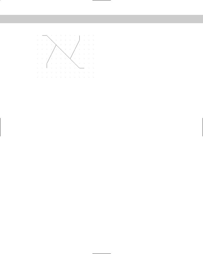
Here’s another example — in this case, a script alef — shown in Figure 32-6:
*4,10,S-ALEF 06C,2,8,(6,5),1,10,(3,016),0
Figure 32-6: A script alef.
Here’s the explanation of the code for the script alef:
On the
CD-ROM
The first code, 06C, creates the line on the left, starting at the top and making it 6 units long.
The second code, 2, lifts up the pen.
The third code, 8, specifies an X,Y displacement, with the pen up.
The fourth and fifth codes, (6,5), move the pen 6 units to the right and 5 units up, to the start of the arc.
The sixth code, 10, introduces an octant arc.
The seventh and eighth codes, (3,016), specify an arc with a radius of 3 that starts at octant 1 and covers 6 octants (to octant 7). (See Figure 32-4 to review the octant codes.)
The last code, 0, ends the definition.
The Express Tools contain a command, MKSHAPE (choose Express Tools Make Shape) that makes shapes for you. You just draw the objects.
The drawing used in the following Step-by-Step exercise on creating a shape, ab32-a.dwg, is in the Drawings folder on the CD-ROM.
Chapter 32 Creating Shapes and Fonts 941
STEP-BY-STEP: Creating a Shape
1.Open ab32-a.dwg from the CD-ROM.
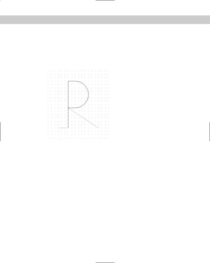
2.Save the file as ab32-01.dwg in your AutoCAD Bible folder. This drawing shows an uppercase P, with dashed lines to indicate space before and after the letter, as shown in Figure 32-7. This is the type of drawing that you might use as a basis for creating a shape definition.
Figure 32-7: An uppercase P.
3.Type notepad on the command line and press Enter at the File to edit: prompt to open a new file.
4.Type the following in Notepad:
*80,15,UCP
2,030,1,0E4,020,12,(0,–8,–127),028,2,8,(9,–6),0
5.Press Enter at the end of the last line. Choose File Save in Notepad and save the file in your AutoCAD Bible folder as ab32-01.shp. Close Notepad.
6.In AutoCAD, type compile . Double-click ab32-01.shp. AutoCAD compiles the .shp file. AutoCAD confirms on the command line that the compilation succeeded. (Press F2 to open the Text Window if necessary.)
7.Type load and choose ab32-01.shx. Click Open. Type shape . To insert the shape, follow the prompts:
Enter shape name or [?]: ucp
Specify insertion point: Pick any point. Specify height <1.0000>:
Specify rotation angle <0>:
8.Save your drawing. It should look like Figure 32-8.