

- •Foreword
- •Preface
- •Is This Book for You?
- •How This Book Is Organized
- •How to Use This Book
- •Doing the Exercises
- •Conventions Used in This Book
- •What the Icons Mean
- •About the CD-ROM
- •Other Information
- •Contacting the Author
- •Acknowledgments
- •Contents at a Glance
- •Contents
- •Getting Acquainted with AutoCAD and AutoCAD LT
- •Starting AutoCAD and AutoCAD LT
- •Creating a New Drawing
- •Using the AutoCAD and AutoCAD LT Interface
- •Creating Your First Drawing
- •Saving a Drawing
- •Summary
- •Creating a New Drawing from a Template
- •Working with Templates
- •Opening a Drawing with Default Settings
- •Opening an Existing Drawing
- •Using an Existing Drawing as a Prototype
- •Saving a Drawing Under a New Name
- •Summary
- •The Command Line
- •Command Techniques
- •Of Mice and Pucks
- •Getting Help
- •Summary
- •Typing Coordinates
- •Displaying Coordinates
- •Picking Coordinates on the Screen
- •Locating Points
- •Summary
- •Unit Types
- •Drawing Limits
- •Understanding Scales
- •Inserting a Title Block
- •Common Setup Options
- •The MVSETUP Command
- •Summary
- •Using the LINE Command
- •Drawing Rectangles
- •Drawing Polygons
- •Creating Construction Lines
- •Creating Rays
- •Summary
- •Drawing Circles
- •Drawing Arcs
- •Creating Ellipses and Elliptical Arcs
- •Making Donuts
- •Placing Points
- •Summary
- •Panning
- •The ZOOM Command
- •Aerial View
- •Named Views
- •Tiled Viewports
- •Snap Rotation
- •User Coordinate Systems
- •Isometric Drawing
- •Summary
- •Editing a Drawing
- •Selecting Objects
- •Summary
- •Copying and Moving Objects
- •Using Construction Commands
- •Creating a Revision Cloud
- •Hiding Objects with a Wipeout
- •Double-Clicking to Edit Objects
- •Grips
- •Editing with the Properties Palette
- •Selection Filters
- •Groups
- •Summary
- •Working with Layers
- •Changing Object Color, Linetype, and Lineweight
- •Working with Linetype Scales
- •Importing Layers and Linetypes from Other Drawings
- •Matching Properties
- •Summary
- •Drawing-Level Information
- •Object-Level Information
- •Measurement Commands
- •AutoCAD’s Calculator
- •Summary
- •Creating Single-Line Text
- •Understanding Text Styles
- •Creating Multiline Text
- •Creating Tables
- •Inserting Fields
- •Managing Text
- •Finding Text in Your Drawing
- •Checking Your Spelling
- •Summary
- •Working with Dimensions
- •Drawing Linear Dimensions
- •Drawing Aligned Dimensions
- •Creating Baseline and Continued Dimensions
- •Dimensioning Arcs and Circles
- •Dimensioning Angles
- •Creating Ordinate Dimensions
- •Drawing Leaders
- •Using Quick Dimension
- •Editing Dimensions
- •Summary
- •Understanding Dimension Styles
- •Defining a New Dimension Style
- •Changing Dimension Styles
- •Creating Geometric Tolerances
- •Summary
- •Creating and Editing Polylines
- •Drawing and Editing Splines
- •Creating Regions
- •Creating Boundaries
- •Creating Hatches
- •Creating and Editing Multilines
- •Creating Dlines
- •Using the SKETCH Command
- •Digitizing Drawings with the TABLET Command
- •Summary
- •Preparing a Drawing for Plotting or Printing
- •Creating a Layout in Paper Space
- •Working with Plot Styles
- •Plotting a Drawing
- •Summary
- •Combining Objects into Blocks
- •Inserting Blocks and Files into Drawings
- •Managing Blocks
- •Using Windows Features
- •Working with Attributes
- •Summary
- •Understanding External References
- •Editing an Xref within Your Drawing
- •Controlling Xref Display
- •Managing Xrefs
- •Summary
- •Preparing for Database Connectivity
- •Connecting to Your Database
- •Linking Data to Drawing Objects
- •Creating Labels
- •Querying with the Query Editor
- •Working with Query Files
- •Summary
- •Working with 3D Coordinates
- •Using Elevation and Thickness
- •Working with the User Coordinate System
- •Summary
- •Working with the Standard Viewpoints
- •Using DDVPOINT
- •Working with the Tripod and Compass
- •Getting a Quick Plan View
- •Shading Your Drawing
- •Using 3D Orbit
- •Using Tiled Viewports
- •Defining a Perspective View
- •Laying Out 3D Drawings
- •Summary
- •Drawing Surfaces with 3DFACE
- •Drawing Surfaces with PFACE
- •Creating Polygon Meshes with 3DMESH
- •Drawing Standard 3D Shapes
- •Drawing a Revolved Surface
- •Drawing an Extruded Surface
- •Drawing Ruled Surfaces
- •Drawing Edge Surfaces
- •Summary
- •Drawing Standard Shapes
- •Creating Extruded Solids
- •Drawing Revolved Solids
- •Creating Complex Solids
- •Sectioning and Slicing Solids
- •Using Editing Commands in 3D
- •Editing Solids
- •Listing Solid Properties
- •Summary
- •Understanding Rendering
- •Creating Lights
- •Creating Scenes
- •Working with Materials
- •Using Backgrounds
- •Doing the Final Render
- •Summary
- •Accessing Drawing Components with the DesignCenter
- •Accessing Drawing Content with Tool Palettes
- •Setting Standards for Drawings
- •Organizing Your Drawings
- •Working with Sheet Sets
- •Maintaining Security
- •Keeping Track of Referenced Files
- •Handling Errors and Crashes
- •Managing Drawings from Prior Releases
- •Summary
- •Importing and Exporting Other File Formats
- •Working with Raster Images
- •Pasting, Linking, and Embedding Objects
- •Summary
- •Sending Drawings
- •Opening Drawings from the Web
- •Creating Object Hyperlinks
- •Publishing Drawings
- •Summary
- •Working with Customizable Files
- •Creating Keyboard Shortcuts for Commands
- •Customizing Toolbars
- •Customizing Tool Palettes
- •Summary
- •Creating Macros with Script Files
- •Creating Slide Shows
- •Creating Slide Libraries
- •Summary
- •Creating Linetypes
- •Creating Hatch Patterns
- •Summary
- •Creating Shapes
- •Creating Fonts
- •Summary
- •Working with Menu Files
- •Customizing a Menu
- •Summary
- •Introducing Visual LISP
- •Getting Help in Visual LISP
- •Working with AutoLISP Expressions
- •Using AutoLISP on the Command Line
- •Creating AutoLISP Files
- •Summary
- •Creating Variables
- •Working with AutoCAD Commands
- •Working with Lists
- •Setting Conditions
- •Managing Drawing Objects
- •Getting Input from the User
- •Putting on the Finishing Touches
- •Summary
- •Understanding Local and Global Variables
- •Working with Visual LISP ActiveX Functions
- •Debugging Code
- •Summary
- •Starting to Work with VBA
- •Writing VBA Code
- •Getting User Input
- •Creating Dialog Boxes
- •Modifying Objects
- •Debugging and Trapping Errors
- •Moving to Advanced Programming
- •A Final Word
- •Installing AutoCAD and AutoCAD LT
- •Configuring AutoCAD
- •Starting AutoCAD Your Way
- •Configuring a Plotter
- •System Requirements
- •Using the CD with Microsoft Windows
- •What’s on the CD
- •Troubleshooting
- •Index

Chapter 34 Understanding AutoLISP and Visual LISP Basics 1001
13.Use the Windows task bar to return to the Visual LISP window.
14.Click the Visual LISP Editor to activate it. Choose Save File on the Visual LISP Standard toolbar. Save the routine as ab34-02.lsp in your AutoCAD Bible folder.
15.Close the Visual LISP window by clicking its Close button. Do not save your drawing.
Summary
This chapter covers the fundamentals of AutoLISP programming and the Visual LISP environment. You read about:
How to open the Visual LISP interface and load and use AutoLISP files
How to use AutoLISP on the command line
What AutoLISP routines look like
How to get help in Visual LISP
The basic structure of AutoLISP syntax as well as how to work with numbers and text
In the next chapter, you examine how to create variables, work with AutoCAD commands and system variables, modify AutoCAD objects (or entities, as they’re often still called in AutoLISP), and work with the fundamental units of AutoLISP, known as lists.
|
|
|

Exploring AutoLISP
Further
AutoLISP offers many features that enable you to create sophisticated programs. These include variables, functions, and conditional structures. You can easily work with drawing coordinates. You
can retrieve information about drawing objects and then modify them. Getting input from the user makes your programs interactive.
AutoCAD LT does not support AutoLISP. This entire chapter is for AutoCAD only.
Creating Variables
A very useful item in most programming languages is the variable. A variable is a symbolic name that can be operated on in a given program. An important part of using variables is that you can assign values to them.
The following example sets the value of 3 for a variable named radius.
(setq radius 3) 3
You can try this example out in Visual LISP in the Console window. If you want to use this variable on the AutoCAD command line, precede it with an exclamation point (!). For example:
Command: !radius 3
The exclamation point before a variable evaluates the value stored in the variable and returns it to the command line. When you use a variable in the Console window that you’ve already set, you don’t need the exclamation point. The Console knows to assume that everything you type there is an AutoLISP expression.
Assigning strings to a variable is as easy as assigning numerals to a variable:
(setq name “Robin”) “Robin”
35C H A P T E R
In This Chapter
Creating variables and functions
Working with AutoCAD commands and system variables
Working with lists
Setting conditions and creating loops
Managing drawing objects
Getting input from the user

1004 Part VII Programming AutoCAD
You can also nest AutoLISP expressions — place one inside the other.
(setq radius (+ 2 1)) 3
As explained in the previous chapter, AutoLISP evaluates LISP expressions from the innermost set of parentheses outward. AutoLISP evaluates (+ 2 1) first, and then assigns the result to the variable radius.
STEP-BY-STEP: Using AutoLISP Variables from within AutoCAD
1.Open a drawing using the acad.dwt template.
2.Type (setq radius (+ 2 1)) . AutoLISP returns 3.
3.Start the CIRCLE command. Specify any center point. At the Specify radius of circle or [Diameter]: prompt, type !radius . AutoCAD draws a circle with a radius of 3 units.
4.Type (setq color “green”) . AutoLISP returns “green”.
5.Type -color . At the Enter default object color [Truecolor/Colorbook] <BYLAYER>: prompt, type !color .
6.Draw a circle. The circle is green because the current color is now green.
7.Save your drawing in your AutoCAD Bible folder as ab35-01.dwg.
Working with AutoCAD Commands
Accessing AutoCAD commands from within AutoLISP is a powerful way to automate commonly used functions. By combining access to commands from AutoLISP with variables as described in the previous section, you gain a great deal of flexibility.
Accessing AutoCAD commands
In the previous chapter, when you looked at an AutoLISP routine (see Figure 34-5), you saw an example of the COMMAND function. You use the COMMAND function in AutoLISP to execute AutoCAD commands. This function treats all subsequent operands as if they were typed at the command line interactively. When programming COMMAND functions in AutoLISP, exactly duplicate what you would do at the command line. For example, to draw a line, you follow the steps shown in the following table. The second column shows how you would accomplish the same action in an AutoLISP routine.
Enter line at the command line |
“line” (or “_line”) |
Specify the start point for the line |
Use a variable, actual coordinates, or |
|
pause for user input. |
Specify the endpoint |
Use a variable, actual coordinates, or |
|
pause for user input. |
Press Enter to end the LINE command |
Use an empty set of two quotation marks |
|
to represent pressing Enter either within a |
|
command or to end a command. |

Chapter 35 Exploring AutoLISP Further 1005
Automatically loading LSP files
AutoCAD automatically loads four AutoLISP files. Two files, acad2005.lsp and acad2005doc.lsp, are specific to AutoCAD 2005. Autodesk recommends that you reserve these files for AutoCAD use. Acad2005.lsp is loaded only once per AutoCAD session when you first load AutoCAD, while acad2005doc.lsp is loaded in the initial session and then each time a drawing is opened.
The other two automatically loaded AutoLISP files are reserved for you, the user. These files are acad.lsp, which is loaded once per AutoCAD session, and acaddoc.lsp, which is loaded every time a drawing is opened. What this means to you is that you can place different initialization routines in each file — one for AutoCAD initialization (acad.lsp) and the other for the initial drawing as well as future drawings. You can place an S::STARTUP function in both acad.lsp and acaddoc.lsp. However, be aware that placing different S::STARTUP functions in both files effectively disables the S::STARTUP function defined in acad.lsp.
You must create both acad.lsp and acaddoc.lsp. However, after you create any AutoLISP routine and save it under either name, you can add additional routines to the same file. AutoCAD knows to automatically load these files, as long as they exist.
The load order of these initialization files is:
1.Acad2005.lsp: Loaded by AutoCAD 2005
2.Acad.lsp: User-defined initialization file loaded once upon loading AutoCAD 2005
3.Acad2005doc.lsp: Document-level initialization file loaded by AutoCAD 2005
4.Acaddoc.lsp: User-defined document-level initialization file
For example, if you’re using the variables startpt and endpt for the start point and endpoint of a line, here’s how you would access the LINE command in an AutoLISP expression:
(command “_line” startpt endpt “”)
Creating functions
Functions always begin with the operator DEFUN. You can define three principal types of functions:
The type you’ve been using thus far precedes the command name defined by DEFUN with c:, which is interpreted by AutoCAD as a command and enables you to use the function by name at the AutoCAD command line. The function becomes usable like any other AutoCAD command.
You can also create a function definition without preceding the name with c:. This type is most valuable when it’s called by other AutoLISP operations. If you need to execute it at the command line, you must enclose the function name in parentheses. Similarly, you can execute functions prefixed with a c: as an AutoLISP expression by enclosing the functions in parentheses, such as (c:circle3).
The third type is S::STARTUP. By defining a function (usually in acaddoc.lsp, which is loaded into every drawing) with the name S::STARTUP, every AutoLISP function in the routine will automatically execute after the drawing has fully initialized. The reason for the S::STARTUP function is to ensure that AutoLISP routines that use the COMMAND function run only after AutoCAD fully initializes the components that can execute commands.

1006 Part VII Programming AutoCAD
When you create an S::STARTUP function, you need to decide where to put it. Chapter 34 briefly explained the difference between acad.lsp and acaddoc.lsp. The need for two files arose because AutoCAD includes MDI, which enables you to open more than one drawing at a time. For more information, see the “Automatically loading LSP files” sidebar. S::STARTUP is a great tool for enhancing productivity. In this way, you can automate whatever general setup operations you normally do at the beginning of a drawing session or for every drawing you open.
Here’s an AutoLISP routine that uses both DEFUN and COMMAND:
(defun c:redline (/ startpt endpt) (terpri)
(setq startpt (getpoint “Select the redline start point:”)) (terpri)
(setq endpt (getpoint “Select the redline end point:”)) (command “_line” startpt endpt “”)
(command “_chprop” “_last” “” “_color” “red” “”)
)
Here’s an explanation of this routine:
The first line of this routine defines a function called redline. Because redline is preceded by c:, you can type redline at the command line when using it within AutoCAD. As you may remember from the discussion of the circle3 routine, the expression
(/ startpt endpt) means that redline has two local variables that are available only to this routine. These variables are used in the next two lines.
The new instruction, terpri, on the second and fourth lines tells AutoCAD to print a blank line at the command line. You can use this to improve readability of the prompts. Otherwise, two or more prompts run together on one line.
Reading the third line from the innermost parenthesis pair outward, AutoCAD obtains the redline’s start point from the user with the prompt Select the redline start point: and sets the variable startpt equal to that start point’s value. Similarly, the fifth line obtains the redline’s endpoint and sets the variable endpt to that value.
Line 6 uses the AutoLISP COMMAND function. It issues the LINE command, specifies the start point and endpoint, and uses a set of empty quotation marks to replicate pressing Enter to end the LINE command.
Line seven analogously uses the same syntax for the CHPROP command. It issues the CHPROP command, selects the line you just used by using the Last Selection option, ends object selection by using the empty set of quotation marks, specifies the Color option, and sets the color to red. Another empty set of quotation marks ends the command.
Line 8 ends the redline routine with a closing parenthesis.
To use this routine, you would follow these steps:
1.Open Visual LISP and start a new file.
2.Type the routine.
3.Save the routine as redline.lsp and place it in AutoCAD’s Support folder or any other folder you may have created for AutoLISP routines and added to AutoCAD’s support-file search path.
Chapter 35 Exploring AutoLISP Further 1007
On the
CD-ROM
4.Load the routine.
5.Switch to AutoCAD.
6.At the command prompt, type redline .
7.In response to the prompts for the start point and endpoint of the redline, choose any two points on-screen. AutoCAD draws a red line between the two points selected.
The file redline.lsp is in the \Results folder on the CD-ROM. Feel free to copy it to your system and play around with it. For example, using your knowledge of the circle3 routine discussed in Chapter 34, you could create a red circle.
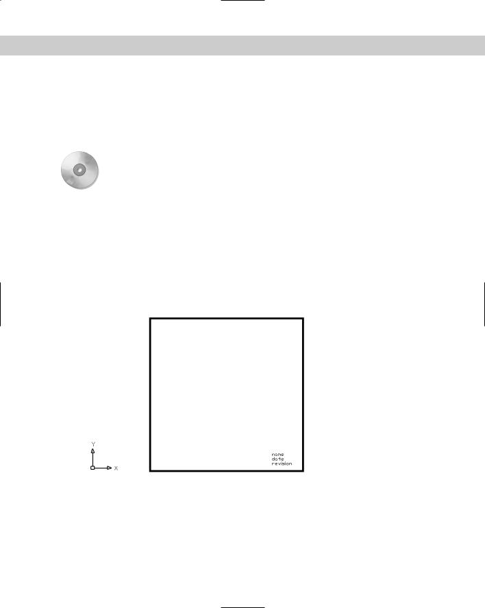
Here is another example of an AutoLISP routine that creates an S::STARTUP function. It uses several of the features I’ve been discussing in this chapter.
(defun s::startup ()
(command “_rectang” “_width” “0.1” “0,0” “10,10”) (command “_text” “8,1” “0.2” “0” “name”)
(command “_text” “8,0.7” “0.2” “0” “date”) (command “_text” “8, 0.4” “0.2” “0” “revision”) (command “_zoom” “_extents”)
)
This routine creates a simple title block and border each time you open a new drawing, as shown in Figure 35-1.
Figure 35-1: The result of the S::STARTUP routine.
In order to use this routine — or one of your own — add this to the end of acaddoc.lsp. AutoCAD 2005 does not come with this file, so the first time you want to use it, you must create it.
1008 Part VII Programming AutoCAD
Caution |
Before using the S::STARTUP function, be sure an S::STARTUP function does not already exist in |
|
the file. Other applications you may have purchased or downloaded may include an |
|
S::STARTUP file. Adding a second S::STARTUP could possibly interfere with the operation of these |
|
other applications. In Notepad, choose Search Find and type s::startup in the Find What |
|
text box. Click Find Next. If an S::STARTUP routine already exists, then add the body of your |
|
S::STARTUP function (minus the first line, which already exists) to the end of the existing |
|
S::STARTUP routine and save the file. |
Creating functions with arguments
You can create functions that accept arguments, sometimes called parameters. An argument is a value that must be supplied with the function. The function then uses the value of that argument in its operation.
Earlier in this chapter, I explained that local variables are placed in parentheses after a slash. Arguments go in the same set of parentheses but before the slash. If there are no local variables, you don’t need the slash. Here is an example of a function with one argument:
(defun chg2red (selected_object)
...
)
To actually use this routine in AutoCAD or within another AutoLISP routine, use the format (chg2red selected_object). The argument is sent to the chg2red routine by adding the argument after the function name, all enclosed in parentheses.
Whenever you use the chg2red function within a routine, you must follow it by its argument. You can obtain the argument by using a variable whose value you’ve set in the routine, by obtaining a value through user input, or by typing in a specific value when you use the function.
The following exercise uses a function that is called from within the routine.
On the |
The file used in the following Step-by-Step exercise, ab35-a.lsp, is in the Drawings folder |
CD-ROM |
on the CD-ROM. If you haven’t already done so, place the CD-ROM in your CD-ROM drive. |
|
STEP-BY-STEP: Using AutoLISP Functions and Commands
1.Start a new drawing using any template.
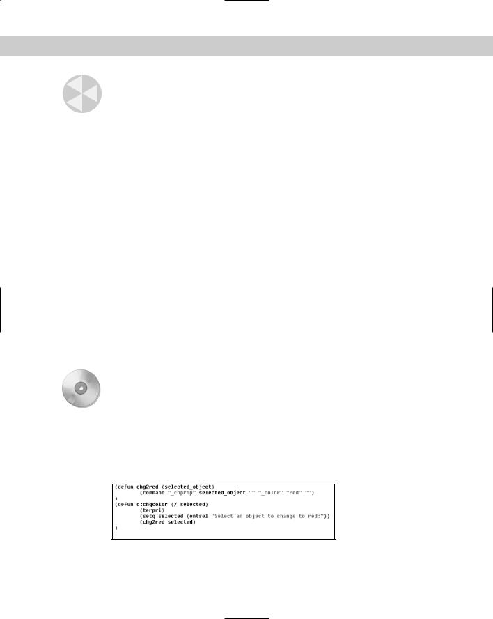
2.Use Windows Explorer to copy ab35-a.lsp from the CD-ROM to AutoCAD’s Support folder or any folder you’ve created for AutoLISP routines and added to AutoCAD’s support-file search path. This file is shown in Figure 35-2.
Figure 35-2: An AutoLISP routine to change an object’s color to red.

Chapter 35 Exploring AutoLISP Further 1009
3.Choose Tools AutoLISP Visual LISP Editor. In Visual LISP, open ab35-a.lsp. The routine appears in the Edit window.
4.Choose Load Active Edit Window.
5.Choose Activate AutoCAD.
6.Draw any object.
7.At the command line, type chgcolor .
8.At the Select an object to change to red: prompt, select the object you drew in Step 6. Watch its color change to red.
Don’t save the routine or your drawing.
Here’s how the routine works:
This routine defines a function, chg2red, which is not preceded by c:. It has one argument, selected_object.
What AutoLISP actually ran when you typed chgcolor in Step 7 is the function c:chgcolor on the fourth line of the routine. In the last AutoLISP statement in that function — (chg2red selected) — the variable selected is derived from the previous step as a result of the operation entsel (entity select).
The variable selected is the argument passed to the function chg2red. The function chg2red now knows what object to operate on.
The function chg2red then uses the CHPROP command to change the object’s color to red.
Note To actually call this function at the command line, you would need to type (chg2red arg), where arg is an argument (in this case, it must be an entity name). Entity names are discussed later in this chapter.
Working with system variables
AutoCAD has a wide variety of system variables to control the drawing environment. Thankfully, the creators of AutoLISP enabled the AutoLISP programmer to automate setting and retrieve AutoCAD system variables.
Don’t get the terms variable and system variable confused. A variable is a value that is stored for use in a routine. A system variable is an AutoCAD setting that changes how AutoCAD works.
To set or retrieve AutoCAD system variables, you use two operators, SETVAR and GETVAR, which can be used on AutoCAD system variables. (You can use SETVAR only on system variables that are not read-only.) Here’s how they work:
SETVAR stands for set variable. You use SETVAR to change a system variable. Place the system variable in quotes, followed by the new value, as in (setvar “cmdecho” 0).
GETVAR stands for get variable. It enables you to obtain the value of any system variable. As soon as you have the value, you can set it to a variable. This is often done so that you can return a system variable to its previous value if you’ve changed it during a routine. Place the system variable in quotes after using GETVAR, as in (getvar “cmdecho”).
1010 Part VII Programming AutoCAD
Although you can use SETVAR and GETVAR on many system variables, here are two system variables that are often changed in an AutoLISP routine:
On the
CD-ROM
In all the AutoLISP routines created thus far, AutoCAD’s command responses could be seen scrolling off the command-line window. The CMDECHO system variable determines whether you see prompts and input during the functioning of AutoLISP’s COMMAND function. By default, echoing is on (set to 1). If you set it to 0, you do not see prompts and input, and the functioning of the AutoLISP routine looks cleaner and runs slightly faster.
The FILEDIA system variable turns on and off the display of dialog boxes that enable you to choose files. Turning off this system variable enables you to work with files on the command line in AutoLISP routines.
The file used in the following Step-by-Step exercise, ab35-a.lsp, is in the Drawings folder on the CD-ROM.
STEP-BY-STEP: Using AutoLISP to Work with System Variables
1.If you did the previous exercise and copied ab35-a.lsp to AutoCAD’s Support folder (or another folder you created for AutoLISP routines and added to AutoCAD’s supportfile search path), open it from that folder. If you did not do the previous exercise, copy ab35-a.lsp from the CD-ROM to AutoCAD’s Support folder or another folder in AutoCAD’s support-file search path.
2.Open a new drawing using the acad.dwt template. Choose Tools AutoLISP Visual LISP Editor to open Visual LISP. Click Open and open ab35-a.lsp. Edit it to read as follows:
(defun chg2red (selected_object)
(command “_chprop” selected_object “” “_color” “red” “”)
)
(defun c:chgcolor (/ selected old_cmdecho) (setq old_cmdecho (getvar “cmdecho”)) (setvar “cmdecho” 0)
(terpri)
(setq selected (entsel “Select an object to change to red:”)) (chg2red selected)
(setvar “cmdecho” old_cmdecho)
)
3.Save the file as ab35-01.lsp in the same location.
4.Choose Load Active Edit Window to load the routine.
5.Draw any object.
6.At the command line, type chgcolor .
7.At the Select an object to change to red: prompt, select the object you drew in Step 5. You no longer see the prompts scrolling by. The object you select turns red, and AutoCAD immediately displays the command prompt.
Don’t save your drawing.