

- •Foreword
- •Preface
- •Is This Book for You?
- •How This Book Is Organized
- •How to Use This Book
- •Doing the Exercises
- •Conventions Used in This Book
- •What the Icons Mean
- •About the CD-ROM
- •Other Information
- •Contacting the Author
- •Acknowledgments
- •Contents at a Glance
- •Contents
- •Getting Acquainted with AutoCAD and AutoCAD LT
- •Starting AutoCAD and AutoCAD LT
- •Creating a New Drawing
- •Using the AutoCAD and AutoCAD LT Interface
- •Creating Your First Drawing
- •Saving a Drawing
- •Summary
- •Creating a New Drawing from a Template
- •Working with Templates
- •Opening a Drawing with Default Settings
- •Opening an Existing Drawing
- •Using an Existing Drawing as a Prototype
- •Saving a Drawing Under a New Name
- •Summary
- •The Command Line
- •Command Techniques
- •Of Mice and Pucks
- •Getting Help
- •Summary
- •Typing Coordinates
- •Displaying Coordinates
- •Picking Coordinates on the Screen
- •Locating Points
- •Summary
- •Unit Types
- •Drawing Limits
- •Understanding Scales
- •Inserting a Title Block
- •Common Setup Options
- •The MVSETUP Command
- •Summary
- •Using the LINE Command
- •Drawing Rectangles
- •Drawing Polygons
- •Creating Construction Lines
- •Creating Rays
- •Summary
- •Drawing Circles
- •Drawing Arcs
- •Creating Ellipses and Elliptical Arcs
- •Making Donuts
- •Placing Points
- •Summary
- •Panning
- •The ZOOM Command
- •Aerial View
- •Named Views
- •Tiled Viewports
- •Snap Rotation
- •User Coordinate Systems
- •Isometric Drawing
- •Summary
- •Editing a Drawing
- •Selecting Objects
- •Summary
- •Copying and Moving Objects
- •Using Construction Commands
- •Creating a Revision Cloud
- •Hiding Objects with a Wipeout
- •Double-Clicking to Edit Objects
- •Grips
- •Editing with the Properties Palette
- •Selection Filters
- •Groups
- •Summary
- •Working with Layers
- •Changing Object Color, Linetype, and Lineweight
- •Working with Linetype Scales
- •Importing Layers and Linetypes from Other Drawings
- •Matching Properties
- •Summary
- •Drawing-Level Information
- •Object-Level Information
- •Measurement Commands
- •AutoCAD’s Calculator
- •Summary
- •Creating Single-Line Text
- •Understanding Text Styles
- •Creating Multiline Text
- •Creating Tables
- •Inserting Fields
- •Managing Text
- •Finding Text in Your Drawing
- •Checking Your Spelling
- •Summary
- •Working with Dimensions
- •Drawing Linear Dimensions
- •Drawing Aligned Dimensions
- •Creating Baseline and Continued Dimensions
- •Dimensioning Arcs and Circles
- •Dimensioning Angles
- •Creating Ordinate Dimensions
- •Drawing Leaders
- •Using Quick Dimension
- •Editing Dimensions
- •Summary
- •Understanding Dimension Styles
- •Defining a New Dimension Style
- •Changing Dimension Styles
- •Creating Geometric Tolerances
- •Summary
- •Creating and Editing Polylines
- •Drawing and Editing Splines
- •Creating Regions
- •Creating Boundaries
- •Creating Hatches
- •Creating and Editing Multilines
- •Creating Dlines
- •Using the SKETCH Command
- •Digitizing Drawings with the TABLET Command
- •Summary
- •Preparing a Drawing for Plotting or Printing
- •Creating a Layout in Paper Space
- •Working with Plot Styles
- •Plotting a Drawing
- •Summary
- •Combining Objects into Blocks
- •Inserting Blocks and Files into Drawings
- •Managing Blocks
- •Using Windows Features
- •Working with Attributes
- •Summary
- •Understanding External References
- •Editing an Xref within Your Drawing
- •Controlling Xref Display
- •Managing Xrefs
- •Summary
- •Preparing for Database Connectivity
- •Connecting to Your Database
- •Linking Data to Drawing Objects
- •Creating Labels
- •Querying with the Query Editor
- •Working with Query Files
- •Summary
- •Working with 3D Coordinates
- •Using Elevation and Thickness
- •Working with the User Coordinate System
- •Summary
- •Working with the Standard Viewpoints
- •Using DDVPOINT
- •Working with the Tripod and Compass
- •Getting a Quick Plan View
- •Shading Your Drawing
- •Using 3D Orbit
- •Using Tiled Viewports
- •Defining a Perspective View
- •Laying Out 3D Drawings
- •Summary
- •Drawing Surfaces with 3DFACE
- •Drawing Surfaces with PFACE
- •Creating Polygon Meshes with 3DMESH
- •Drawing Standard 3D Shapes
- •Drawing a Revolved Surface
- •Drawing an Extruded Surface
- •Drawing Ruled Surfaces
- •Drawing Edge Surfaces
- •Summary
- •Drawing Standard Shapes
- •Creating Extruded Solids
- •Drawing Revolved Solids
- •Creating Complex Solids
- •Sectioning and Slicing Solids
- •Using Editing Commands in 3D
- •Editing Solids
- •Listing Solid Properties
- •Summary
- •Understanding Rendering
- •Creating Lights
- •Creating Scenes
- •Working with Materials
- •Using Backgrounds
- •Doing the Final Render
- •Summary
- •Accessing Drawing Components with the DesignCenter
- •Accessing Drawing Content with Tool Palettes
- •Setting Standards for Drawings
- •Organizing Your Drawings
- •Working with Sheet Sets
- •Maintaining Security
- •Keeping Track of Referenced Files
- •Handling Errors and Crashes
- •Managing Drawings from Prior Releases
- •Summary
- •Importing and Exporting Other File Formats
- •Working with Raster Images
- •Pasting, Linking, and Embedding Objects
- •Summary
- •Sending Drawings
- •Opening Drawings from the Web
- •Creating Object Hyperlinks
- •Publishing Drawings
- •Summary
- •Working with Customizable Files
- •Creating Keyboard Shortcuts for Commands
- •Customizing Toolbars
- •Customizing Tool Palettes
- •Summary
- •Creating Macros with Script Files
- •Creating Slide Shows
- •Creating Slide Libraries
- •Summary
- •Creating Linetypes
- •Creating Hatch Patterns
- •Summary
- •Creating Shapes
- •Creating Fonts
- •Summary
- •Working with Menu Files
- •Customizing a Menu
- •Summary
- •Introducing Visual LISP
- •Getting Help in Visual LISP
- •Working with AutoLISP Expressions
- •Using AutoLISP on the Command Line
- •Creating AutoLISP Files
- •Summary
- •Creating Variables
- •Working with AutoCAD Commands
- •Working with Lists
- •Setting Conditions
- •Managing Drawing Objects
- •Getting Input from the User
- •Putting on the Finishing Touches
- •Summary
- •Understanding Local and Global Variables
- •Working with Visual LISP ActiveX Functions
- •Debugging Code
- •Summary
- •Starting to Work with VBA
- •Writing VBA Code
- •Getting User Input
- •Creating Dialog Boxes
- •Modifying Objects
- •Debugging and Trapping Errors
- •Moving to Advanced Programming
- •A Final Word
- •Installing AutoCAD and AutoCAD LT
- •Configuring AutoCAD
- •Starting AutoCAD Your Way
- •Configuring a Plotter
- •System Requirements
- •Using the CD with Microsoft Windows
- •What’s on the CD
- •Troubleshooting
- •Index

Chapter 24 Creating Solids and Editing in 3D |
711 |
On the |
3D Kitchen Plus is a library of 3D kitchen cabinets. You can choose from several models. |
CD-ROM |
Look for it in Software\Chap24\3D Kitchen Plus. Flatten is a program that flattens |
|
everything except blocks from 3D to 2D. |
Sectioning and Slicing Solids
In many mechanical drawings, you need to show a cross-section of your models. A crosssection displays the inside of a 3D object. The SECTION and SLICE commands are both used to create cross-section views of your 3D models.
Using the SECTION command
The SECTION command creates a 2D region from a cross-section of a 3D model along a plane you specify. The original objects are left untouched. Figure 24-20 shows a region created using the SECTION command.
Region created using SECTION
Figure 24-20: The region created using SECTION is shown with a dashed line.
Tip |
The SECTION command creates the region on the current layer. Make the current layer color |
|
different from the object layer color so that the region is clearly visible. |
To use the SECTION command, choose Section from the Solids toolbar. Select the object you want to section. AutoCAD displays the Specify first point on Section plane
by [Object/Zaxis/View/XY/YZ/ZX/3points] <3points>: prompt. Use these options to define the plane of the cross-section. Table 24-1 explains how to use the options.
712 Part IV Drawing in Three Dimensions
|
Table 24-1: SECTION Options |
|
|
Option |
Description |
|
|
Object |
Enables you to choose a circle, ellipse, arc, spline, or 2D polyline. |
Zaxis |
Defines the plane by defining a Z axis. The sectioning plane is then the XY plane |
|
perpendicular to the Z axis you defined. You define the Z axis by first specifying a point |
|
on the sectioning plane. This point is the 0,0,0 point (for purposes of this command only) |
|
where the sectioning plane and the Z axis meet. Then you pick a point on the Z axis. |
View |
Defines the section plane parallel to the current view at the intersection of a point you |
|
specify. |
XY |
Defines the section plane parallel to the XY plane at the intersection of a point you specify. |
YZ |
Defines the section plane parallel to the YZ plane at the intersection of a point you specify. |
ZX |
Defines the section plane parallel to the ZX plane at the intersection of a point you specify. |
3points |
This is the default. Specify three points to define the section plane. Using object snaps is |
|
a good idea. |
|
|
You can move the region you create and view it separately to spot errors in your models.
Using the SLICE command
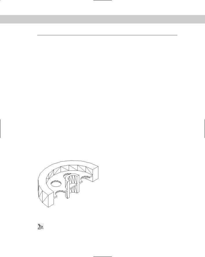
The SLICE command slices a solid into two parts along a plane. The original solids are modified but can be reunited with UNION. You can delete either part or keep both. Figure 24-21 shows the result of slicing a model, after one-half of the model has been deleted. This can help to identify problems in the construction of the model. For example, this slice reveals a fault with the model — the flat disk continues through the central tube — not the desired result.
Figure 24-21: The result of slicing a solid and retaining one of the resulting pieces.
To use the SLICE command, choose Slice from the Solids toolbar. Select the object you want to slice. AutoCAD displays the Specify first point on slicing plane by
[Object/Zaxis/View/XY/YZ/ZX/3points] <3points>: prompt. Use these options to define the plane of the cross-section. The options are the same as for the SECTION command and are explained in Table 24-1.
Chapter 24 Creating Solids and Editing in 3D |
713 |
On the |
The drawing used in the following Step-by-Step exercise on slicing solids, ab24-03.dwg, is |
CD-ROM |
in the Results folder on the CD-ROM. |
STEP-BY-STEP: Slicing Solids
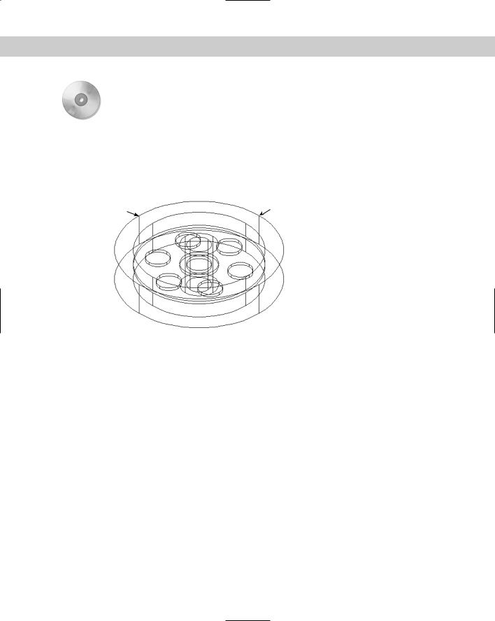
1.If you have ab24-03.dwg open from the previous exercise, use it. Do a regen to remove the hidden view. If you don’t have it open, open it from your AutoCAD Bible folder or from the Results folder of the CD-ROM. Make sure that OSNAP is on. Set running object snaps for endpoint, midpoint, center, and quadrant. Make sure you have both the Solids and the Solids Editing toolbars open. The drawing is shown in Figure 24-22.
4 |
3 |
1
2
Figure 24-22: The 3D model for slicing.
2.Save your drawing as ab24-04.dwg in your AutoCAD Bible folder.
3. Choose Slice from the Solids toolbar. Follow the prompts:
Select objects: Select the solid model.
Select objects: Right-click.
Specify first point on slicing plane by [Object/Zaxis/View/XY/YZ/ ZX/3points]
<3points>: Pick the quadrant at 1 in Figure 24-22.
Specify second point on plane: Pick the quadrant at 2. Specify third point on plane: Pick the quadrant at 3.
Specify a point on desired side of the plane or [keep Both sides]:
Pick the model at 4.
4.As mentioned earlier, the slicing reveals an error — the disk cuts through the central tube, as shown in Figure 24-23. To fix the error now, choose Zoom Realtime from the Standard toolbar and zoom in so the model takes up the entire screen.
5.Start the CIRCLE command. At the Specify center point for circle or [3P/2P/ Ttr (tan tan radius)]: prompt, pick the midpoint at 1 in Figure 24-23. At the
Specify radius of circle or [Diameter]: prompt, pick the endpoint at 2.
714 Part IV Drawing in Three Dimensions
1
2
Figure 24-23: The solid after slicing and deleting one-half of it.
6.Choose Extrude from the Solids toolbar. Select the new circle. Set the height of extrusion to 16 and accept the default taper angle of 0 (zero).
7.Choose Subtract from the Solids Editing toolbar. At the Select solids and regions to subtract from... Select objects: prompt, select the large solid and rightclick to end object selection. At the Select solids and regions to subtract...
Select objects: prompt, select the new extruded circle you just drew and right-click. AutoCAD subtracts the extruded circle from the larger model.
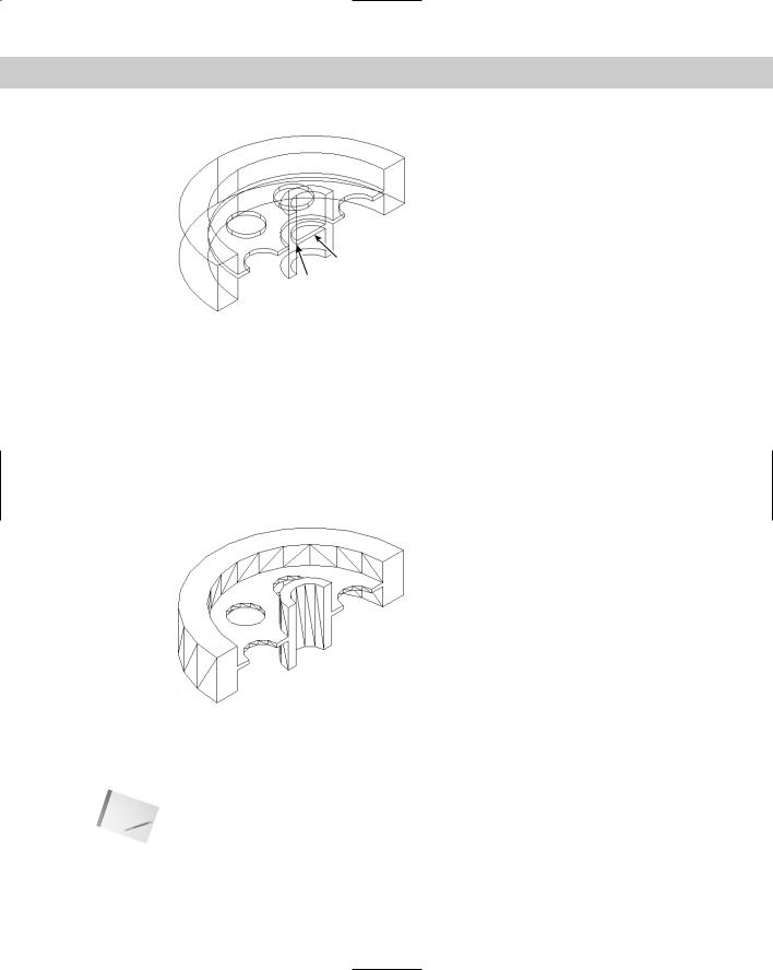
8.Use the HIDE command to hide the model. Your drawing should look like Figure 24-24.
Figure 24-24: The solid after subtracting the extruded circle and doing a hide.
9.Save your drawing. If you’re continuing on to the next Step-by-Step exercise, keep the drawing open.
Note If you wanted to correct the model, you could subtract out the circle as you just did in the exercise, mirror the entire model, and use UNION to make the two halves whole. Mirroring in 3D is covered in the next section. You could also undo the slice as soon as you saw the error and make the correction on the entire model.