

98 |
Part II Drawing in Two Dimensions |
STEP-BY-STEP: Using the LINE Command
1.Start a new drawing by using the acad.dwt template.
2.Save the drawing in your AutoCAD Bible folder as ab06-01.dwg.
3.Start the LINE command. At the Specify first point: prompt, choose any point in the center of your drawing.
4.Click ORTHO on the status bar.
5.Move the cursor to the right in the 0-degree direction and type .4667 .
6.Type @.7341<129 .
7.Move the cursor to the right in the 0-degree direction and type .4668 .
8.That was a mistake. Type u .
9. The Specify next point or [Close/Undo]: prompt reappears. With the cursor still in the 0-degree direction, type .4667 .
10.Type c to close the figure. This ends the LINE command.
11.Start the LINE command again.
12.At the Specify first point: prompt, press Enter. The line starts at the previous endpoint.
13.Type @.8071<270 and press Enter to end the LINE command.
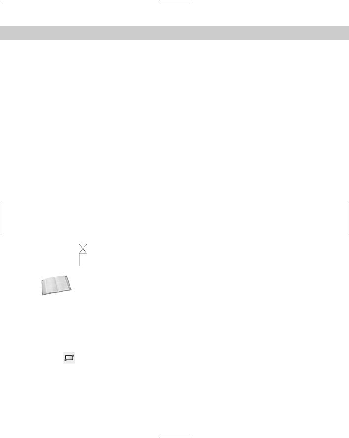
14.Save your drawing. It should look like Figure 6-1.
Figure 6-1: The completed gate valve symbol.
Cross- Other aspects of lines are covered elsewhere in the book. Chapter 11 explains how to draw Reference dashed and dotted lines. Chapter 16 explains how to create polylines, which combine line
segments and curves into one object. Chapter 16 also covers multilines — sets of parallel lines that you draw all at once.
Drawing Rectangles
The RECTANG command draws rectangles. Rectangles are used in all disciplines. The RECTANG command has a number of options that specify how the rectangle appears.
Use the RECTANG command to create a rectangle by specifying the two diagonal corners. Choose Rectangle from the Draw toolbar.

Chapter 6 Drawing Simple Lines |
99 |
The RECTANG command prompts you for the two corner points. Specify these two points to create the rectangle. You can use any method of specifying coordinates. For example, if you know the rectangle should be 6 inches wide and 3 inches high, you can specify the second point as @6,3.
After you specify the first corner, you can specify the length and the width of the rectangle instead of the second corner. Here are the prompts for specifying the length and width of a rectangle:
Specify other corner point or [Dimensions]: Choose the Dimensions option.
Specify length for rectangles <0.0000>: Type the length and press Enter.
Specify width for rectangles <0.0000>: Type the width and press Enter. Specify other corner point or [Dimensions]:Pick a point to specify where you want the rectangle.
As soon as you specify the length and width, four possible rectangles are possible, as shown in Figure 6-2. As you move your mouse cursor around the first corner you specified, AutoCAD or AutoCAD LT displays these rectangles. Click when you see the one that you want.
First corner point
Figure 6-2: After you specify the first corner, a length, and a width, choose which of four possible rectangles you want.
Note |
After you set the dimensions, they remain as defaults for future rectangles that you draw. As |
|
a result, you can use the Dimensions option to quickly draw a number of identical rectangles. |
Cross- |
You can chamfer and fillet the corners as you create the rectangle. Chapter 10 covers cham- |
Reference |
fering and filleting. You can specify a width for the rectangle’s line (see Chapter 16). You can |
|
|
|
also create a 3D box by using the elevation and thickness options (see Chapter 21). The |
|
RECTANG command creates a polyline, meaning that all four sides of the rectangle are one |
|
object, instead of four separate line objects. Chapter 16 covers polylines. |
100 Part II Drawing in Two Dimensions
Drawing Polygons
The POLYGON command enables you to draw multisided closed figures with equal side lengths. You can draw polygons that have from 3 to 1,024 sides. To draw a polygon,
choose Polygon from the Draw toolbar.
First specify the number of sides. Then choose one of three methods of defining the polygon, as described in Table 6-1.
Table 6-1: POLYGON Command Options |
|
|
|
Option |
Description |
|
|
Edge |
Right-click and choose the Edge option. Specify the two endpoints of any |
|
edge of the polygon to complete the polygon. |
Inscribed in circle |
After specifying the center, right-click and choose Inscribed in Circle. Then |
|
specify the radius from the center to a vertex (point). This defines the |
|
polygon with reference to an imaginary circle whose circumference |
|
touches all the vertices of the polygon. |
Circumscribed about circle |
After specifying the center, right-click and choose Circumscribed about |
|
Circle. Then specify the radius from the center to the midpoint of a side. |
|
This defines the polygon with reference to an imaginary circle whose |
|
circumference touches all the midpoints of the polygon’s sides. |
|
|
If you type a number for the radius, the bottom edge of the polygon is horizontal. However, if you pick a point for the radius with your mouse, you can specify the orientation of the polygon. Rotate the mouse cursor around the center, and you see the polygon rotate. Pick when you like what you see.
Cross- |
When you type a number for the radius, the bottom edge actually aligns with the snap rota- |
Reference |
tion angle, which is usually 0. Chapter 8 explains how to change this angle. |
|
The POLYGON command creates a polyline, meaning that the entire polygon is one object, rather than a series of line segments.
In the exercise that follows, I indicate inches with a double-prime (") and feet with a prime ('). You may find this notation clearer when a measurement has both feet and inches, but you do not actually need to type the double-prime for inches. When you have a measurement that is only in inches, it saves time to leave out the double-prime.
On the |
The drawing used in this Step-by-Step exercise on drawing rectangles and polygons, ab06-a. |
CD-ROM |
dwg, is in the Drawings folder on the CD-ROM. |
STEP-BY-STEP: Drawing Rectangles and Polygons
1. Open ab06-a.dwg from the CD-ROM.

Chapter 6 Drawing Simple Lines 101
2.Save the drawing in your AutoCAD Bible folder as ab06-02.dwg. Verify that snap and grid are on, set at 1". OSNAP should be off.
3. Choose Rectangle from the Draw toolbar.
4.At the Specify first corner point or [Chamfer/Elevation/Fillet/Thickness/
Width]: prompt, move the cursor to 0'-1",0'-1" and click. At the Specify other corner point or [Dimensions]: prompt, type @2'1",1'9" .
5.Start the RECTANG command again. At the Specify first corner point or [Chamfer/ Elevation/Fillet/Thickness/Width]: prompt, Shift+right-click and choose the From object snap. Shift+right-click again and choose the Endpoint object
snap. Pick the bottom-left corner of the rectangle. At the <Offset>: prompt, type @2,2 to start the second rectangle 2 inches up and 2 inches to the right of the first rectangle.
6. At the Specify other corner point or [Dimensions]: prompt, type @1'9",1'3" .
7.Right-click and choose Repeat Rectangle to start the RECTANG command again. At the
prompt, find 0'8",1'7" (on a snap point) and click. At the Specify other corner point or [Dimensions]: prompt, type @11,2 . (You don’t need to type the double-prime for inches.)
8.Again, start the RECTANG command. At the prompt, find 1'1",1'8" and click. At the
Specify other corner point or [Dimensions]: prompt, type @1,-5 .
9.Start the POLYGON command. At the Enter number of sides <4>: prompt,
type 5 . At the Specify center of polygon or [Edge]: prompt, type 10,1'8 to indicate the center.
10.At the Enter an option [Inscribed in circle/Circumscribed about circle]
<I>: prompt, press Enter to accept the default. This means you indicate the radius from the center to the vertices. (If your prompt shows <C> as the default, type i .)
11.At the Specify radius of circle: prompt, type .5 . AutoCAD or AutoCAD LT draws the pentagon.
12.Repeat Steps 9 through 11 using a center of 1'5,1'8.
13.Start the POLYGON command again. At the Enter number of sides <5>: prompt, type 3 .
14.At the Specify center of polygon or [Edge]: prompt, right-click and choose the Edge option.
15.At the Specify first endpoint of edge: prompt, choose the top-left corner of the faucet rectangle (1'1",1'8"), which is on a snap point.
16.At the Specify second endpoint of edge: prompt, choose the top-right corner of the faucet rectangle to complete the triangle.
17.Turn off the grid to get a better look at the drawing. You have completed the sink, which should look like Figure 6-3. Save your drawing.