

- •Foreword
- •Preface
- •Is This Book for You?
- •How This Book Is Organized
- •How to Use This Book
- •Doing the Exercises
- •Conventions Used in This Book
- •What the Icons Mean
- •About the CD-ROM
- •Other Information
- •Contacting the Author
- •Acknowledgments
- •Contents at a Glance
- •Contents
- •Getting Acquainted with AutoCAD and AutoCAD LT
- •Starting AutoCAD and AutoCAD LT
- •Creating a New Drawing
- •Using the AutoCAD and AutoCAD LT Interface
- •Creating Your First Drawing
- •Saving a Drawing
- •Summary
- •Creating a New Drawing from a Template
- •Working with Templates
- •Opening a Drawing with Default Settings
- •Opening an Existing Drawing
- •Using an Existing Drawing as a Prototype
- •Saving a Drawing Under a New Name
- •Summary
- •The Command Line
- •Command Techniques
- •Of Mice and Pucks
- •Getting Help
- •Summary
- •Typing Coordinates
- •Displaying Coordinates
- •Picking Coordinates on the Screen
- •Locating Points
- •Summary
- •Unit Types
- •Drawing Limits
- •Understanding Scales
- •Inserting a Title Block
- •Common Setup Options
- •The MVSETUP Command
- •Summary
- •Using the LINE Command
- •Drawing Rectangles
- •Drawing Polygons
- •Creating Construction Lines
- •Creating Rays
- •Summary
- •Drawing Circles
- •Drawing Arcs
- •Creating Ellipses and Elliptical Arcs
- •Making Donuts
- •Placing Points
- •Summary
- •Panning
- •The ZOOM Command
- •Aerial View
- •Named Views
- •Tiled Viewports
- •Snap Rotation
- •User Coordinate Systems
- •Isometric Drawing
- •Summary
- •Editing a Drawing
- •Selecting Objects
- •Summary
- •Copying and Moving Objects
- •Using Construction Commands
- •Creating a Revision Cloud
- •Hiding Objects with a Wipeout
- •Double-Clicking to Edit Objects
- •Grips
- •Editing with the Properties Palette
- •Selection Filters
- •Groups
- •Summary
- •Working with Layers
- •Changing Object Color, Linetype, and Lineweight
- •Working with Linetype Scales
- •Importing Layers and Linetypes from Other Drawings
- •Matching Properties
- •Summary
- •Drawing-Level Information
- •Object-Level Information
- •Measurement Commands
- •AutoCAD’s Calculator
- •Summary
- •Creating Single-Line Text
- •Understanding Text Styles
- •Creating Multiline Text
- •Creating Tables
- •Inserting Fields
- •Managing Text
- •Finding Text in Your Drawing
- •Checking Your Spelling
- •Summary
- •Working with Dimensions
- •Drawing Linear Dimensions
- •Drawing Aligned Dimensions
- •Creating Baseline and Continued Dimensions
- •Dimensioning Arcs and Circles
- •Dimensioning Angles
- •Creating Ordinate Dimensions
- •Drawing Leaders
- •Using Quick Dimension
- •Editing Dimensions
- •Summary
- •Understanding Dimension Styles
- •Defining a New Dimension Style
- •Changing Dimension Styles
- •Creating Geometric Tolerances
- •Summary
- •Creating and Editing Polylines
- •Drawing and Editing Splines
- •Creating Regions
- •Creating Boundaries
- •Creating Hatches
- •Creating and Editing Multilines
- •Creating Dlines
- •Using the SKETCH Command
- •Digitizing Drawings with the TABLET Command
- •Summary
- •Preparing a Drawing for Plotting or Printing
- •Creating a Layout in Paper Space
- •Working with Plot Styles
- •Plotting a Drawing
- •Summary
- •Combining Objects into Blocks
- •Inserting Blocks and Files into Drawings
- •Managing Blocks
- •Using Windows Features
- •Working with Attributes
- •Summary
- •Understanding External References
- •Editing an Xref within Your Drawing
- •Controlling Xref Display
- •Managing Xrefs
- •Summary
- •Preparing for Database Connectivity
- •Connecting to Your Database
- •Linking Data to Drawing Objects
- •Creating Labels
- •Querying with the Query Editor
- •Working with Query Files
- •Summary
- •Working with 3D Coordinates
- •Using Elevation and Thickness
- •Working with the User Coordinate System
- •Summary
- •Working with the Standard Viewpoints
- •Using DDVPOINT
- •Working with the Tripod and Compass
- •Getting a Quick Plan View
- •Shading Your Drawing
- •Using 3D Orbit
- •Using Tiled Viewports
- •Defining a Perspective View
- •Laying Out 3D Drawings
- •Summary
- •Drawing Surfaces with 3DFACE
- •Drawing Surfaces with PFACE
- •Creating Polygon Meshes with 3DMESH
- •Drawing Standard 3D Shapes
- •Drawing a Revolved Surface
- •Drawing an Extruded Surface
- •Drawing Ruled Surfaces
- •Drawing Edge Surfaces
- •Summary
- •Drawing Standard Shapes
- •Creating Extruded Solids
- •Drawing Revolved Solids
- •Creating Complex Solids
- •Sectioning and Slicing Solids
- •Using Editing Commands in 3D
- •Editing Solids
- •Listing Solid Properties
- •Summary
- •Understanding Rendering
- •Creating Lights
- •Creating Scenes
- •Working with Materials
- •Using Backgrounds
- •Doing the Final Render
- •Summary
- •Accessing Drawing Components with the DesignCenter
- •Accessing Drawing Content with Tool Palettes
- •Setting Standards for Drawings
- •Organizing Your Drawings
- •Working with Sheet Sets
- •Maintaining Security
- •Keeping Track of Referenced Files
- •Handling Errors and Crashes
- •Managing Drawings from Prior Releases
- •Summary
- •Importing and Exporting Other File Formats
- •Working with Raster Images
- •Pasting, Linking, and Embedding Objects
- •Summary
- •Sending Drawings
- •Opening Drawings from the Web
- •Creating Object Hyperlinks
- •Publishing Drawings
- •Summary
- •Working with Customizable Files
- •Creating Keyboard Shortcuts for Commands
- •Customizing Toolbars
- •Customizing Tool Palettes
- •Summary
- •Creating Macros with Script Files
- •Creating Slide Shows
- •Creating Slide Libraries
- •Summary
- •Creating Linetypes
- •Creating Hatch Patterns
- •Summary
- •Creating Shapes
- •Creating Fonts
- •Summary
- •Working with Menu Files
- •Customizing a Menu
- •Summary
- •Introducing Visual LISP
- •Getting Help in Visual LISP
- •Working with AutoLISP Expressions
- •Using AutoLISP on the Command Line
- •Creating AutoLISP Files
- •Summary
- •Creating Variables
- •Working with AutoCAD Commands
- •Working with Lists
- •Setting Conditions
- •Managing Drawing Objects
- •Getting Input from the User
- •Putting on the Finishing Touches
- •Summary
- •Understanding Local and Global Variables
- •Working with Visual LISP ActiveX Functions
- •Debugging Code
- •Summary
- •Starting to Work with VBA
- •Writing VBA Code
- •Getting User Input
- •Creating Dialog Boxes
- •Modifying Objects
- •Debugging and Trapping Errors
- •Moving to Advanced Programming
- •A Final Word
- •Installing AutoCAD and AutoCAD LT
- •Configuring AutoCAD
- •Starting AutoCAD Your Way
- •Configuring a Plotter
- •System Requirements
- •Using the CD with Microsoft Windows
- •What’s on the CD
- •Troubleshooting
- •Index

Chapter 30 Creating Macros and Slide Shows with Script Files |
919 |
Summary
This chapter explained how to create script files to automate repetitive commands. You read about the following:
Creating script files that contain commands, options, and values in command-line format
Running script files from within a drawing or when loading AutoCAD or AutoCAD LT
Creating slides from the display in your viewport and creating a script file that displays several slides, one after another, resulting in a slide show
Organizing your slides into slide libraries
In the next chapter, you read about how to create your own linetypes and hatch patterns.
|
|
|

Creating Your Own
Linetypes and
Hatch Patterns
As you know, AutoCAD and AutoCAD LT come with a large number of linetypes and hatch patterns. However, sometimes these may
not serve your particular needs. You can create your own linetypes and hatch patterns and use them in your drawings in the same way you use the linetypes and hatch patterns that come with the software. Linetypes are useful whenever you don’t want a continuous linetype. They apply not only to lines, but also to polylines, arcs, ellipses, wireframes, and solids — in fact, to most objects. You use hatch patterns to fill in closed (or almost closed) areas.
Creating Linetypes
There are two types of linetypes: simple and complex. Simple linetypes consist of dashes and dots only. Complex linetypes usually have dashes and/or dots but contain text and/or shapes as well.
The default linetype file is acad.lin for AutoCAD and aclt.lin for AutoCAD LT. You can add your own linetype definitions to this file or create your own linetype files. Linetype files are text files and must have a file extension of .lin. Of course, be sure to make a backup copy of acad.lin or aclt.lin before you edit it.
Creating simple linetypes
In the syntax for creating simple linetypes, each linetype is defined using two lines of text. The first line contains the linetype name and an optional description, formatted as follows:
*linetype name[, description]
Here are the points to note:
Always start the definition with an asterisk.
The description is limited to 47 characters.
If you include a description, precede it with a comma.
31C H A P T E R
In This Chapter
Creating linetypes
Creating hatch patterns
922 Part VI Customizing AutoCAD
The second line of the linetype syntax is its definition. With simple linetypes, you’re limited to dashes, dots, and spaces, measured in units and shown as follows:
A dash is indicated by a positive number.
A dot is indicated by a 0.
A space is indicated by a negative number.
Each item is separated by a comma, there are no spaces, and the maximum line length is 80 characters.
Each line must start with the letter A.
The following definition creates a line with two dashes of 0.25 units, followed by two dots, all separated by spaces of 0.1 units.
*seeingdouble, Future hedge line A,.25,–.1,.25,–.1,0,–.1,0,–.1
|
The result is shown in Figure 31-1. |
|
Figure 31-1: The seeingdouble linetype. |
|
If you feel quite confident, you can even create linetypes on the fly, using the command-line |
|
form of the LINETYPE command. Type -linetype and use the Create option. Follow the |
|
prompts and type the linetype definition on the command line. If you make a mistake, you |
|
still have to open the linetype file in a text editor to make corrections. |
Tip |
If your linetype definition will include both dashes and dots, you’ll get best results if you start a |
|
linetype definition with the dash. Starting the definition with a dash is a matter of aesthetics, |
|
perhaps, but such a line connects better to other lines. |
STEP-BY-STEP: Creating a Simple Linetype
1.Open a drawing using the acad.dwt or aclt.dwt template.
2.Save your drawing as ab31-01.dwg in your AutoCAD Bible folder.
3.In Windows, choose Start Run. Type notepad and click OK to open Notepad.
4.Type the following:
*3dotsandadash, temporary fencing A,.5,–.25,0,–.1,0,–.1,0,–.25
5.Press Enter after the last line. Save the file as ab31-01.lin in your AutoCAD Bible folder and close Notepad.
6.In your drawing, choose Layer Properties Manager on the Layers toolbar and then click the New Layer icon. Name the new layer tfence. Set its color to red.
7.Click Continuous in the Linetype column to open the Select Linetype dialog box. Click Load.
8.In the Load or Reload Linetypes dialog box, click File. In the Select Linetype File dialog box, find ab31-01.lin in your AutoCAD Bible folder, choose it, and click Open.
Chapter 31 Creating Your Own Linetypes and Hatch Patterns 923
9.Back in the Load or Reload Linetypes dialog box, choose 3dotsandadash and click OK.
10.Again, in the Select Linetype dialog box, choose 3dotsandadash and click OK. The layer tfence now shows the correct linetype. Click Current and then OK.
11.Start the LINE command and turn on ORTHO. Draw any line to see the linetype. Save your drawing. The linetype should look like Figure 31-2.
Figure 31-2: The 3dotsandadash linetype.
Creating complex linetypes
A complex linetype includes either shapes or text in the linetype definition. Figure 31-3 shows an example of each.
Complex linetype definitions are similar to those for simple linetypes, except that they add a definition for a shape or text.
Figure 31-3: Complex linetypes include shapes or text.
Shapes are covered in the next chapter — for now you only need to know that they’re contained in files with the file extension .shx.
The first line of the linetype definition is the same as for simple linetypes. The second line of the definition can contain all the same features as those for a simple linetype. However, you add the special shape or text definition in square brackets:
Syntax for shapes: [shapename,shxfilename,details]
Syntax for text: [“text string”,textstyle,details]
details refers to an optional series of rotation, scale, and offset specifications that you can add to the definition. Table 31-1 describes these specifications.
The following complex linetype definition uses a shape and has no details:
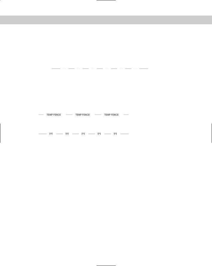
*TEMPFENCE, FENCE SHAPE AND DASH A,.5,–.25,[FENCE,”C:\AUTOCAD BIBLE\FENCE.SHX”],–.5
Note that the specification for the shape is simply part of the rest of the definition that includes a dash and spaces before and after the shape. The shape is enclosed in both commas and square brackets. The first part of the shape definition is the name of the shape (which is defined in the shape’s definition file), and the second part is the name of the shape file. In this case, the shape file is not in the support-file search path, so the entire path needs to be specified. Don’t forget to use quotation marks around the shape filename if the folder name or filename contains embedded spaces.

924 Part VI Customizing AutoCAD
Tip |
Note that the space after the shape (created with the –.5 code) is larger than the space before |
|
it (created with the –.25). You need to allow for the space that the shape takes up. This is |
|
largely a matter of trial and error, but if you know the shape definition well, you can make a |
|
good estimate. When you go back and change the linetype definition (if your first trial was an |
|
error), don’t forget to reload the linetype (using the Load option). |
|
The following complex linetype definition uses text and has no details: |
|
*TFENCE, DASH & TEXT |
|
A,.5,–.25,[“TEMP FENCE”,FENCE],–1.5 |
|
Again, the specification for the text is placed within a linetype definition that includes a dash |
|
and spaces. The first part of the text definition is the text string, which is always in quotation |
|
marks. The second part of the definition is the text style. As with the previous linetype defini- |
|
tion containing a shape, the space after the text is larger than the space before, to leave room |
|
for the text. |
|
You must define the text style in the drawing before you load the linetype. |
|
Table 31-1 lists the details that you can add to both the shape and text portion of complex |
|
linetype definitions. |
Table 31-1: Optional Details for Shapes and Text in Complex Linetype Definitions
Detail |
Syntax |
Description |
|
|
|
Relative rotation |
R=## |
Rotates the shape or text relative to the angle of the line you draw. This |
|
|
number is in degrees unless you put a g (for grads) or r (for radians) |
|
|
after it. |
Absolute rotation |
A=## |
Rotates the shape or text based on the World Coordinate System, regardless |
|
|
of the angle of the line. Because the default is a relative rotation of 0, you |
|
|
can use absolute rotation to keep text facing upright, no matter what the |
|
|
direction of the line. This number is in degrees unless you put a g (for |
|
|
grads) or r (for radians) after it. |
Scale |
S=## |
Scales the text or shape. This scale is multiplied by any scale contained in |
|
|
a shape definition or height in a text style. If you use a text style with a |
|
|
height of 0, this scale number defines the text’s height. |
X offset |
X=## |
A positive number moves the shape or text toward the endpoint of the |
|
|
line. A negative number moves the shape or text toward the start point of |
|
|
the line. You can use an X offset to place a shape or text along a continuous |
|
|
linetype. You can also use an X offset to adjust the spacing of a shape or text |
|
|
between dashes, instead of changing the spaces before or after the dashes. |
Y offset |
Y=## |
Moves the shape or text perpendicular to the direction of the line. A |
|
|
positive number moves the shape or text up if the line is drawn from left |
|
|
to right. Use a Y offset to center text and shapes along a linetype. |
|
|
|
* Although using an absolute rotation of 0 might sound like a good idea for complex linetypes with text, if you use the linetype at varying angles or on curves, you may find that the text shifts to an undesirable location due to the text’s justification point.
Chapter 31 Creating Your Own Linetypes and Hatch Patterns 925
Here is a definition that includes a shape with a scale and a Y offset:
*TEMPFENCE, FENCE SHAPE AND DASH
A,.5,–.25,[FENCE,”C:\AUTOCAD BIBLE\FENCE.SHX”,S=.025,Y=-.07],–.5
This shape definition scales the shape to 0.025 of its original size. This results in the linetype shown in Figure 31-4. Of course, in order to scale the shape, you need to know its original size. You can use the SHAPE command to insert a shape and get an idea of what it looks like. In this case, the shape’s original definition is much too large for a linetype and needs to be scaled down.
Figure 31-4: The TEMPFENCE linetype.
The shape definition also moves the shape in the minus Y direction by 0.07 units. This nicely centers the shape within the linetype.
Caution |
When you create drawings using shapes or custom fonts, as in the case of complex linetypes, |
|
you need to include the shape files or font files when you distribute the drawings to others. |
By including more involved shapes in a complex linetype and not much else, you can create a linetype that is, for all practical purposes, a series of shapes displayed one after the other. You can create some interesting effects in this way.
You can find several complex linetypes at the end of the acad.lin or aclt.lin linetype definition file. Look at their definitions and try them out to get ideas for your own complex linetypes. Express Tools (in AutoCAD only) have a command, MKLTYPE (choose Express Tools Make Linetype) that automatically creates linetypes, even complex ones.
Note |
To find the location of acad.lin or aclt.lin, choose Tools Options and click the Files tab. |
|
Double-click the first item, Support File Search Path, to display the location of the support files. |
On the |
The drawing used in the following Step-by-Step exercise on creating a complex linetype, |
CD-ROM |
ab31-a.dwg, is in the Drawings folder on the CD-ROM. |
STEP-BY-STEP: Creating a Complex Linetype
1.Open ab31-a.dwg from the CD-ROM.
2.Save the file as ab31-02.dwg in your AutoCAD Bible folder. This drawing is a simple plan for a trailer park.
3.Choose Format Text Style. Click New and type TVCABLE for the Style Name. Click OK. In the Font Name drop-down list, choose Arial. Click Apply and then Close.
4.In Windows, choose Start Run. Type notepad and click OK. Notepad opens. Type the following:
*TV, Buried television cable A,.5,-.5,[“TV”,TVCABLE,S=.3,X=-.1,Y=-.15],-.75