

- •Foreword
- •Preface
- •Is This Book for You?
- •How This Book Is Organized
- •How to Use This Book
- •Doing the Exercises
- •Conventions Used in This Book
- •What the Icons Mean
- •About the CD-ROM
- •Other Information
- •Contacting the Author
- •Acknowledgments
- •Contents at a Glance
- •Contents
- •Getting Acquainted with AutoCAD and AutoCAD LT
- •Starting AutoCAD and AutoCAD LT
- •Creating a New Drawing
- •Using the AutoCAD and AutoCAD LT Interface
- •Creating Your First Drawing
- •Saving a Drawing
- •Summary
- •Creating a New Drawing from a Template
- •Working with Templates
- •Opening a Drawing with Default Settings
- •Opening an Existing Drawing
- •Using an Existing Drawing as a Prototype
- •Saving a Drawing Under a New Name
- •Summary
- •The Command Line
- •Command Techniques
- •Of Mice and Pucks
- •Getting Help
- •Summary
- •Typing Coordinates
- •Displaying Coordinates
- •Picking Coordinates on the Screen
- •Locating Points
- •Summary
- •Unit Types
- •Drawing Limits
- •Understanding Scales
- •Inserting a Title Block
- •Common Setup Options
- •The MVSETUP Command
- •Summary
- •Using the LINE Command
- •Drawing Rectangles
- •Drawing Polygons
- •Creating Construction Lines
- •Creating Rays
- •Summary
- •Drawing Circles
- •Drawing Arcs
- •Creating Ellipses and Elliptical Arcs
- •Making Donuts
- •Placing Points
- •Summary
- •Panning
- •The ZOOM Command
- •Aerial View
- •Named Views
- •Tiled Viewports
- •Snap Rotation
- •User Coordinate Systems
- •Isometric Drawing
- •Summary
- •Editing a Drawing
- •Selecting Objects
- •Summary
- •Copying and Moving Objects
- •Using Construction Commands
- •Creating a Revision Cloud
- •Hiding Objects with a Wipeout
- •Double-Clicking to Edit Objects
- •Grips
- •Editing with the Properties Palette
- •Selection Filters
- •Groups
- •Summary
- •Working with Layers
- •Changing Object Color, Linetype, and Lineweight
- •Working with Linetype Scales
- •Importing Layers and Linetypes from Other Drawings
- •Matching Properties
- •Summary
- •Drawing-Level Information
- •Object-Level Information
- •Measurement Commands
- •AutoCAD’s Calculator
- •Summary
- •Creating Single-Line Text
- •Understanding Text Styles
- •Creating Multiline Text
- •Creating Tables
- •Inserting Fields
- •Managing Text
- •Finding Text in Your Drawing
- •Checking Your Spelling
- •Summary
- •Working with Dimensions
- •Drawing Linear Dimensions
- •Drawing Aligned Dimensions
- •Creating Baseline and Continued Dimensions
- •Dimensioning Arcs and Circles
- •Dimensioning Angles
- •Creating Ordinate Dimensions
- •Drawing Leaders
- •Using Quick Dimension
- •Editing Dimensions
- •Summary
- •Understanding Dimension Styles
- •Defining a New Dimension Style
- •Changing Dimension Styles
- •Creating Geometric Tolerances
- •Summary
- •Creating and Editing Polylines
- •Drawing and Editing Splines
- •Creating Regions
- •Creating Boundaries
- •Creating Hatches
- •Creating and Editing Multilines
- •Creating Dlines
- •Using the SKETCH Command
- •Digitizing Drawings with the TABLET Command
- •Summary
- •Preparing a Drawing for Plotting or Printing
- •Creating a Layout in Paper Space
- •Working with Plot Styles
- •Plotting a Drawing
- •Summary
- •Combining Objects into Blocks
- •Inserting Blocks and Files into Drawings
- •Managing Blocks
- •Using Windows Features
- •Working with Attributes
- •Summary
- •Understanding External References
- •Editing an Xref within Your Drawing
- •Controlling Xref Display
- •Managing Xrefs
- •Summary
- •Preparing for Database Connectivity
- •Connecting to Your Database
- •Linking Data to Drawing Objects
- •Creating Labels
- •Querying with the Query Editor
- •Working with Query Files
- •Summary
- •Working with 3D Coordinates
- •Using Elevation and Thickness
- •Working with the User Coordinate System
- •Summary
- •Working with the Standard Viewpoints
- •Using DDVPOINT
- •Working with the Tripod and Compass
- •Getting a Quick Plan View
- •Shading Your Drawing
- •Using 3D Orbit
- •Using Tiled Viewports
- •Defining a Perspective View
- •Laying Out 3D Drawings
- •Summary
- •Drawing Surfaces with 3DFACE
- •Drawing Surfaces with PFACE
- •Creating Polygon Meshes with 3DMESH
- •Drawing Standard 3D Shapes
- •Drawing a Revolved Surface
- •Drawing an Extruded Surface
- •Drawing Ruled Surfaces
- •Drawing Edge Surfaces
- •Summary
- •Drawing Standard Shapes
- •Creating Extruded Solids
- •Drawing Revolved Solids
- •Creating Complex Solids
- •Sectioning and Slicing Solids
- •Using Editing Commands in 3D
- •Editing Solids
- •Listing Solid Properties
- •Summary
- •Understanding Rendering
- •Creating Lights
- •Creating Scenes
- •Working with Materials
- •Using Backgrounds
- •Doing the Final Render
- •Summary
- •Accessing Drawing Components with the DesignCenter
- •Accessing Drawing Content with Tool Palettes
- •Setting Standards for Drawings
- •Organizing Your Drawings
- •Working with Sheet Sets
- •Maintaining Security
- •Keeping Track of Referenced Files
- •Handling Errors and Crashes
- •Managing Drawings from Prior Releases
- •Summary
- •Importing and Exporting Other File Formats
- •Working with Raster Images
- •Pasting, Linking, and Embedding Objects
- •Summary
- •Sending Drawings
- •Opening Drawings from the Web
- •Creating Object Hyperlinks
- •Publishing Drawings
- •Summary
- •Working with Customizable Files
- •Creating Keyboard Shortcuts for Commands
- •Customizing Toolbars
- •Customizing Tool Palettes
- •Summary
- •Creating Macros with Script Files
- •Creating Slide Shows
- •Creating Slide Libraries
- •Summary
- •Creating Linetypes
- •Creating Hatch Patterns
- •Summary
- •Creating Shapes
- •Creating Fonts
- •Summary
- •Working with Menu Files
- •Customizing a Menu
- •Summary
- •Introducing Visual LISP
- •Getting Help in Visual LISP
- •Working with AutoLISP Expressions
- •Using AutoLISP on the Command Line
- •Creating AutoLISP Files
- •Summary
- •Creating Variables
- •Working with AutoCAD Commands
- •Working with Lists
- •Setting Conditions
- •Managing Drawing Objects
- •Getting Input from the User
- •Putting on the Finishing Touches
- •Summary
- •Understanding Local and Global Variables
- •Working with Visual LISP ActiveX Functions
- •Debugging Code
- •Summary
- •Starting to Work with VBA
- •Writing VBA Code
- •Getting User Input
- •Creating Dialog Boxes
- •Modifying Objects
- •Debugging and Trapping Errors
- •Moving to Advanced Programming
- •A Final Word
- •Installing AutoCAD and AutoCAD LT
- •Configuring AutoCAD
- •Starting AutoCAD Your Way
- •Configuring a Plotter
- •System Requirements
- •Using the CD with Microsoft Windows
- •What’s on the CD
- •Troubleshooting
- •Index
Chapter 12 Getting Information from Your Drawing |
293 |
4.In the exercise on calculating area earlier in this chapter, you calculated a total area of 306975.04, in units of inches. To calculate what that is in square feet, type cal . At the Expression: prompt, type 306975.04/144 . AutoCAD calculates 2131.77.
5.In the Step-by-Step exercise on the DIVIDE command earlier in this chapter, you divided
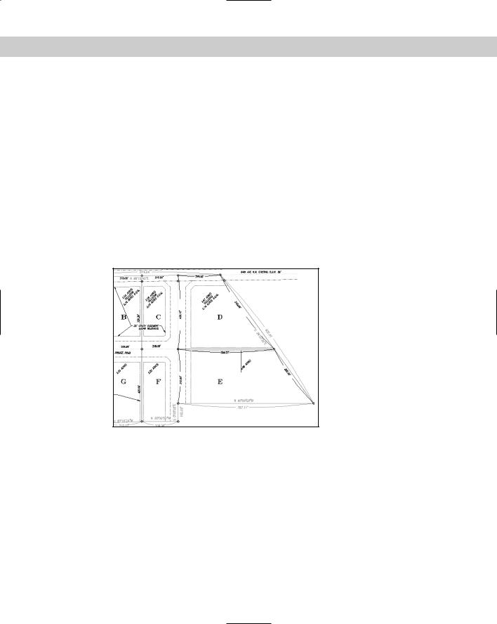
a line into three segments by placing two points on the line. You can use CAL to calculate the length of those segments. Type cal . At the Expression: prompt, type abs(endend)/3 . The command prompts you for the two endpoint snaps. Pick the two ends of the line at ¡ in Figure 12-15. AutoCAD calculates 262.37.
6.Suppose that you want to draw a line starting from the intersection of two intersecting lines going from corner to diagonally opposite corner and ending perpendicular to the
top line of the land parcel. Start the LINE command. At the Specify first point: prompt, type 'cal . At the Expression: prompt, type ill(end,end,end,end) . The command prompts you for four endpoints. Pick the endpoints (in Figure 12-15) at 1 and 2 to define the first line, and then at 3 and 4 to define the second line. AutoCAD starts the line at the intersection of the two lines. At the Specify next point or [Undo]:: prompt, choose the Perpendicular object snap and pick 5. Figure 12-16 shows the result.
Figure 12-16: Using CAL, you can calculate the intersection of two lines without drawing the lines.
7. Save your drawing.
Summary
A great deal of information is available to you in each drawing. In this chapter you read about:
Getting a general status listing
Listing system variable settings
Tracking drawing time

294 Part II Drawing in Two Dimensions
Getting information about individual objects by using the LIST, DIST, and ID command
Calculating area and perimeters
Using the Properties palette to display all of an object’s properties
Dividing and measuring objects by placing point objects along them
Using AutoCAD’s calculator to use calculated results as part of your command input In the next chapter, I explain how to create and edit text.
Creating Text
All drawings include text that labels or explains the objects in the drawing. Such text is often called annotation. In each release, the
capabilities of the text function have improved so that you can now easily format and edit text to provide a professional appearance to your drawing. A wide array of font, alignment, and spacing options are available. You can also import text from a word processor. This chapter tells you all you need to know about creating text in AutoCAD and AutoCAD LT.
Creating Single-Line Text
A great deal of text in a drawing consists of short labels or comments. Use single-line text when you want each line of text to be a separate object or when you’re creating a small amount of text. Single-line text has fewer options than the multiline text that I explain later in this chapter, but it’s easy to create and to place accurately in a drawing.
Creating a single line of text using the defaults for font, height, and so on is very simple. Choose Draw Text Single Line Text. This starts the DTEXT command. DTEXT stands for dynamic text. You can see the text on the screen as you type it. Follow the prompts:
Current text style: “Standard” Text height: 0.2000
Specify start point of text or [Justify/Style]: Pick a start point for the text.
Specify height <0.2000>: Type a height, or press Enter to accept the default.
Specify rotation angle of text <0>: Type a rotation angle, or press Enter to accept the default.
Enter text: Type one line of text. Press Enter when you are finished.
Enter text: Press Enter to end the command.
Note You must actually press Enter to end the command. You cannot use the Return button of the mouse or the Spacebar.
The next section covers the Justify option. The Style option is discussed later in this chapter.
Single lines of text are very common in drafting. DTEXT continues to prompt you for lines of text so that you can type line after line. Unfortunately, you cannot control the spacing between the lines.
13C H A P T E R
In This Chapter
Creating and editing single-line text
Understanding text styles
Creating, editing, and formatting multiline (paragraph) text
Creating tables
Automating with fields
Managing text to improve performance
Using the Find command
Checking spelling

296 Part II Drawing in Two Dimensions
On the
CD-ROM
It (for the TEXT command) and Idt (for DTEXT) let you specify the spacing between lines of text as you create them. Look in \Software\Chap13\It. Txtstack, in \Software\ Chap13\txtstack, adjusts spacing between lines of single-line text. You can use txt2mtxt to convert single-line text to multiline text. It’s in \Software\Chap13\txt2mtxt. These programs work in AutoCAD only.
Thanks to Leonid Nemirovsky, http://home.pacifier.com/~nemi, for creating It.lsp and Idt.lsp at my request.
One advantage of DTEXT is that each line of text is a separate object, making it easy to move or copy individual lines of text.
DTEXT remembers the location of the previous line of text even if you’ve used other commands in the meantime. To continue text below the last line of text you created, press Enter at the Specify start point of text or [Justify/Style]: prompt.
Cross- |
You can also create text connected to arrows that point to objects, using the LEADER and |
Reference |
QLEADER commands. Chapter 14 covers the QLEADER command. |
|
Justifying single-line text
When you pick a start point for text, the relationship between the start point and the actual letters is determined by the justification. The start point is also called the insertion point. When you want to refer to text by using object snaps, you use the Insert object snap. If you select text without first choosing a command, grips appear at the insertion point as well as the bottom-left corner.
By default, text is left-justified. To change the text’s justification, right-click and choose Justify at the Specify start point of text or [Justify/Style]: prompt. The command responds with this bewildering prompt:
Enter an option [Align/Fit/Center/Middle/Right/TL/TC/TR/ML/MC/MR/BL/ BC/BR]:
Align and Fit offer two ways to fit text into a specified space. Both respond with the same two prompts:
Specify first endpoint of text baseline:
Specify second endpoint of text baseline:
Specify the beginning and the end of the text line. Align then prompts you for the text and squeezes or stretches the text to fit within the text line. The height of the text changes accordingly to maintain the proportions of the font.
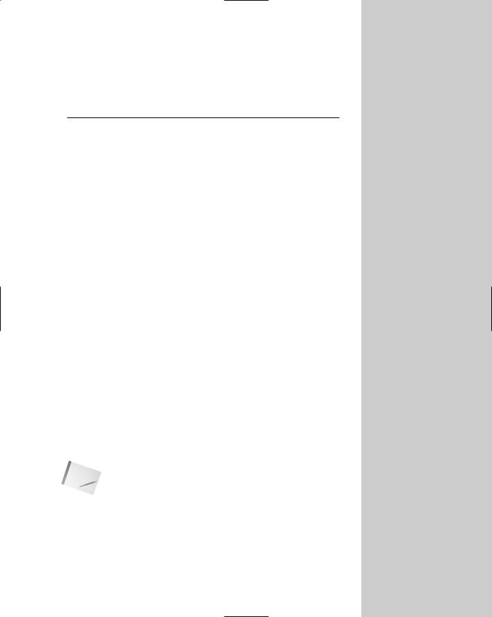
Fit adds the Specify height <0.2000>: prompt. Type in the height you want and then type the text. Fit also squeezes or stretches the text to fit within the text line but maintains the text height you specified, distorting the font letters to fit the space. Figure 13-1 shows an example of normal, fitted, and aligned single-line text.
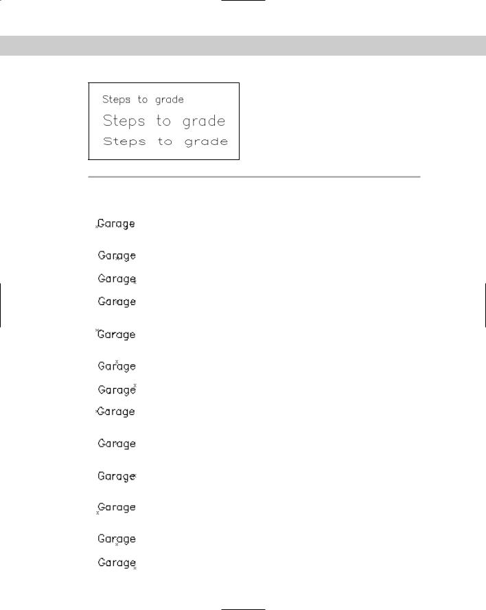
The other justification options (listed in Table 13-1) specify the placement of the text’s insertion point in relationship to the text line. Each insertion point is marked with a small x.
Chapter 13 Creating Text 297
Figure 13-1: Normal (left-justified), aligned, and fitted text.
|
Table 13-1: Text Justification Options |
|
|
|
|
Example |
Option |
Description |
|
|
|
|
Left |
Because this is the default justification, there is no suboption for left- |
|
|
justification when you choose the Justify option. The insertion point |
|
|
is on the baseline. |
|
Center |
Text is centered around the insertion point. The insertion point is on |
|
|
the baseline. |
|
Right |
Text is right-justified from the insertion point. The insertion point is |
|
|
on the baseline. |
|
Middle |
Text is centered both vertically and horizontally. The vertical center |
|
|
point is measured from the bottom of the lowest to the top of the |
|
|
tallest possible letter. |
|
Top Left |
Text is left-justified and the insertion point is at the top of the highest |
|
|
possible letter. For some fonts the insertion point appears slightly |
|
|
above the highest letter; for others it appears exactly at the top. |
|
Top Center |
Text is centered and the insertion point is at the top of the highest |
|
|
possible letter. |
|
Top Right |
Text is right-justified and the insertion point is at the top of the |
|
|
highest possible letter. |
|
Middle Left |
Text is left-justified and centered vertically. The vertical center point is |
|
|
measured from the bottom of the lowest to the top of the tallest |
|
|
possible letter. |
|
Middle Center |
Text is centered both horizontally and vertically. The vertical center |
|
|
point is measured from the bottom of the lowest to the top of the |
|
|
tallest possible letter. |
|
Middle Right |
Text is right-justified and centered vertically. The vertical center point |
|
|
is measured from the bottom of the lowest to the top of the tallest |
|
|
possible letter. |
|
Bottom Left |
Text is left-justified. The insertion point is below the lowest descending |
|
|
letter. For some fonts the insertion point appears slightly below the |
|
|
lowest letter; for others, it appears exactly at the bottom. |
|
Bottom Center |
Text is centered. The insertion point is below the lowest descending |
|
|
letter. |
|
Bottom Right |
Text is right-justified. The insertion point is below the lowest |
|
|
descending letter. |
|
|
|
298 Part II Drawing in Two Dimensions
Tip If you know the option abbreviation of the justification you want, you can use it at the
Specify start point of text or [Justify/Style]: prompt.
If you choose a justification that centers or right-justifies, the text does not appear with the proper justification until after you press Enter for the second time and return to the command prompt.
Setting the height
Setting the height of text is fairly straightforward. The default is 0.2 units but this is not suitable for all applications. The main point to consider is the scale factor. If you’re drawing a house and plan to plot it at 1"=8' (1=96), you need to figure out how big to make the text so that you can still read it when it is scaled down.
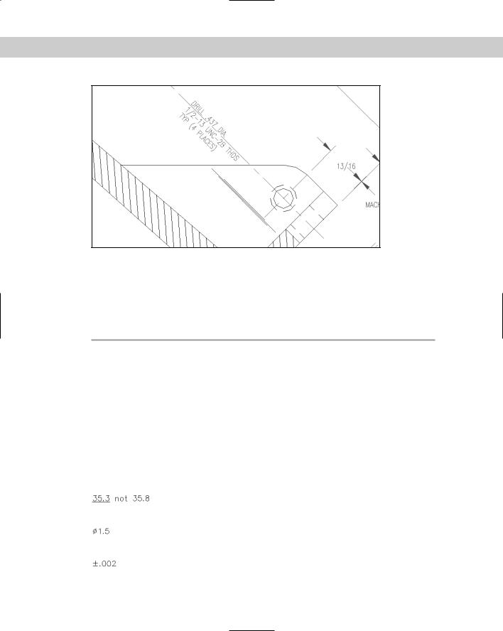
For example, if you want the text to be 0.2 units high and your scale factor is 96, your text needs to be 19.2 inches high (0.2×96). On the other hand, if you’re drawing a very small object, such as a computer chip, and your scale is 0.10, your text needs to be 0.02 inches high. The dimension text in Figure 13-2 is 5 inches high, but at a scale factor of 64, it plots at 5⁄64 inches high.
Figure 13-2: The dimension text in this drawing is 5 inches high.
AutoCAD and AutoCAD LT calculate text height in units. Most word processors calculate text height in points. A point is 1⁄72 of an inch. Therefore, 12-point text, a standard for most business letters, is about 0.17 inches high. The default of 0.2 units, if you’re using inches as your unit, is just over 14 points, which is usually appropriate for annotating a drawing. (You don’t usually hold a drawing as close as a letter, so a larger point size is appropriate.)
For information about changing the scale of text, see the section “Editing single-line text” later in this chapter.
Setting the rotation angle
The final prompt in DTEXT is the rotation angle. This angle applies to the entire line of text, not to individual characters. (You can specify slanted text — called obliqued text — using the STYLE command covered later in this chapter.) Figure 13-3 shows text rotated at 315 degrees.
Chapter 13 Creating Text 299
Figure 13-3: Text rotated at 315 degrees.
Adding special characters and formatting
The DTEXT command does not offer the same type of formatting options available for paragraph text (covered later in this chapter). Therefore, you have to use codes to create special characters and formats. These codes are shown in Table 13-2.
|
Table 13-2: Special Character Codes for Text Fonts |
|
|
Code |
Results |
|
|
%%o |
Toggles overscore mode on/off. |
%%u |
Toggles underscore mode on/off. |
%%d |
Draws degree symbol (°). |
%%p |
Draws plus/minus tolerance symbol (±). |
%%c |
Draws circle diameter dimensioning symbol (Ø). |
|
|
Figure 13-4 shows text using some of these codes, along with the entries that created them.
%%u35.3%%u not 35.8 Figure 13-4: Using special characters and formatting with text fonts.
%%c1.5
%%p.002
300 Part II Drawing in Two Dimensions
On the |
The drawing used in the following Step-by-Step exercise on creating text with DTEXT, 13-a. |
CD-ROM |
dwg, is in the Drawings folder on the CD-ROM. |
STEP-BY-STEP: Creating Text with DTEXT
1.Open ab13-a.dwg from your CD-ROM.
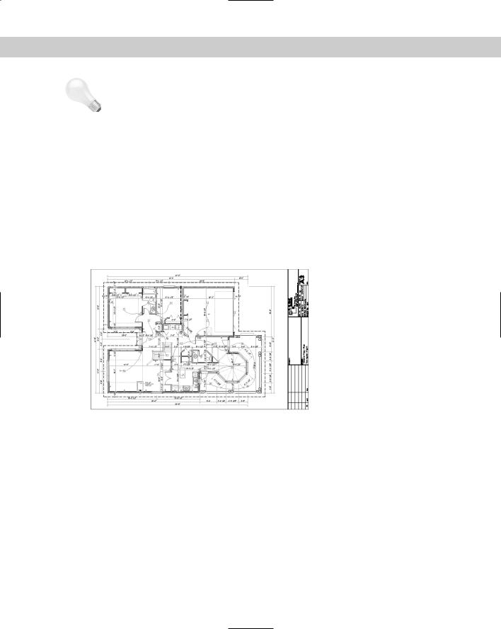
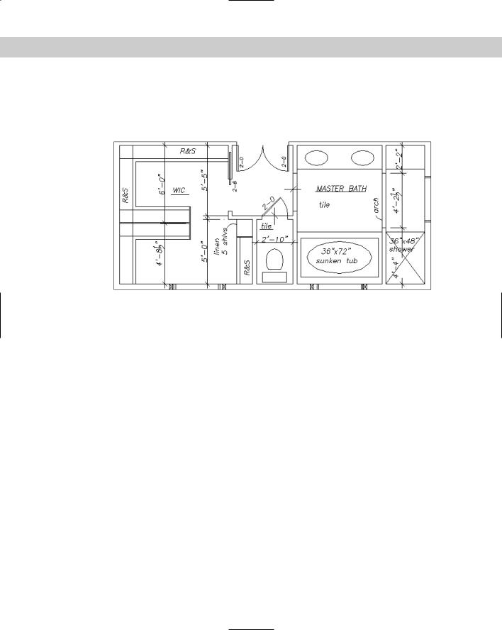
2.Save the file as ab13-01.dwg in your AutoCAD Bible folder. This is a master-bathroom plan drawing, as shown in Figure 13-5. Make sure OSNAP is on. Set running object snaps for endpoint, midpoint, and intersection.
2 |
3 |
|
|
1 |
|
Figure 13-5: The master bathroom.
3.Choose Draw Text Single Line Text. Follow the prompts:
Current text style: “ROMANS” Text height: 0'-4 1/2"
Specify start point of text or [Justify/Style]: Right-click and choose Justify.
Enter an option [Align/Fit/Center/Middle/Right/TL/TC/TR/ML/MC/MR/BL/ BC/BR]: Right-click and choose BC.
Specify bottom-center point of text: Use the Midpoint running object snap to pick 1 in Figure 13-5.
Specify rotation angle of text <0>: Pick the endpoint at 2. Enter text: 2-0
Enter text:
4.Start the DTEXT command again. Follow the prompts:
Specify start point of text or [Justify/Style]: Right-click and choose Justify.
Enter an option [Align/Fit/Center/Middle/Right/TL/TC/TR/ML/MC/MR/BL/ BC/BR]: Right-click and choose Middle.
Specify middle point of text: Pick 3 in Figure 13-5. (This point doesn’t have to be exact.)
Chapter 13 Creating Text 301
Specify rotation angle of text <45>: 0
Enter text: %%UMASTER BATH
Enter text:
5. Save your drawing. It should look like Figure 13-6.
Figure 13-6: The master-bathroom plan drawing with added single-line text.
Using the TEXT command
The TEXT command was the original command for creating text. DTEXT was an update, showing the characters on your screen as you typed. The relationship between these commands is as follows:
When used in a drawing, the TEXT and DTEXT commands function identically.
You can type -text on the command line to get the original TEXT behavior, which ends the command after one line of text.
Only the TEXT command works in script files, menus, or AutoLISP routines. (See Parts VI and VII of this book for more information.)
Editing single-line text
As with any drawing object, the need often arises to edit your text. You can edit single-line text in two ways.
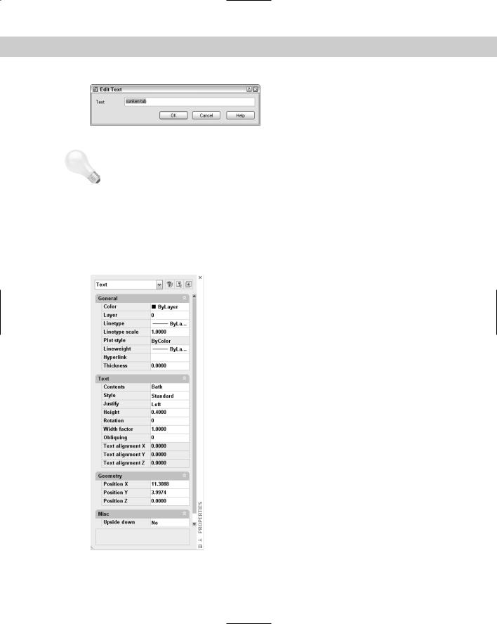
The most common way to edit single-line text is to use the DDEDIT command. Double-click the text. Remember that each line of text created with DTEXT or TEXT is a separate object. The Edit Text dialog box opens with your text highlighted in an edit box, as shown in Figure 13-7. You can start typing to completely replace the text or click where you want to change part of the text and use standard Windows techniques to edit the text. Click OK or press Enter to make the changes and return to your drawing.
302 Part II Drawing in Two Dimensions
|
Figure 13-7: The Edit Text dialog box. |
|
Tip |
If you start the DDEDIT command by choosing Modify Objects Text Edit (or typing |
|
|
DDEDIT on the command line), you’re prompted to select an annotation object. Select the |
|
|
object, and the Edit Text window opens. When you click OK, you’re again prompted to select |
|
|
an object. The command continues to prompt you for objects until you press Enter at the |
|
|
prompt. Use this method when you want to edit several lines of text. |
|
|
You can also change text using the Properties palette. Select any text object and click Proper- |
|
|
ties on the Standard toolbar to open the Properties palette, as shown in Figure 13-8. Here you |
|
|
can edit not only the text content but also every other conceivable property, including layer, |
|
|
linetype, lineweight, color, insertion point, justification, rotation angle, and several other |
|
|
properties that I cover in the next section on text styles. |
|
|
|
Figure 13-8: The Properties palette lets you edit all text |
|
|
|
|
|
properties, including text content, in one place. |
|
|
|
Chapter 13 Creating Text 303
Scaling text
You can change the scale of selected text (either one text object or several at once) without moving the text insertion point using the SCALETEXT command. All the text objects stay in their original location.
To use SCALETEXT, follow these steps:
1.Choose Modify Object Text Scale.
2.Select the text objects to scale.
3.At the Enter a base point option for scaling [Existing/Left/Center/ Middle/Right/TL/TC/TR/ML/MC/MR/BL/BC/BR] <Existing>: prompt, press Enter to
use the existing insertion point of the selected text or choose a new base point. (Your last choice for this prompt becomes the new default, so if you used another option, type e .) These options are the same as the Justify options described earlier in this chapter.
4.At the Specify new height or [Match object/Scale factor] <3/32>: prompt, right-click and choose Scale factor to specify a scale factor, just as you would for the SCALE command (see Chapter 9.) You can also type a new height or use the Match Object option to match the height of the selected text objects to another existing text object. The prompt asks you to select an object with the desired height.
5.If you chose the Scale Factor option, type the factor you want at the Specify scale factor or [Reference] <2>: prompt.
6.If you want to specify the scale factor with reference to existing text or a value, use the Reference option. At the Specify reference length <1>: prompt, type a length or specify two points that measure the reference length. At the Specify new length: prompt, type a value or pick two points to indicate the new length.
Justifying text
The JUSTIFYTEXT command lets you change the justification of selected text objects without moving the text. To use JUSTIFYTEXT, choose Modify Object Text Justify. Then select the text objects you want to modify. At the Enter a justification option [Left/ Align/Fit/Center/Middle/Right/TL/TC/TR/ML/MC/MR/BL/BC/BR] <Left>: prompt, right-click and choose the justification you want.
On the |
The drawing used in the following Step-by-Step exercise on editing text, ab13-b.dwg, is in |
CD-ROM |
the Drawings folder on the CD-ROM. |
STEP-BY-STEP: Editing Text
1.Open ab13-b.dwg from your CD-ROM.
2.Save the file as ab13-02.dwg in your AutoCAD Bible folder. This is an air and vacuum release valve, as shown in Figure 13-9.
3.Double-click the text 1/2" piping. The Edit Text dialog box opens. Highlight the text 1/2 and type 3/8. Click OK. The text changes.
4.Choose Properties from the Standard toolbar. Click Quick Select in the Properties palette. In the Quick Select dialog box, choose Text from the Object Type drop-down list. In the Operator drop-down list, choose Select All. Click OK to select all the text objects in the drawing.