

- •Foreword
- •Preface
- •Is This Book for You?
- •How This Book Is Organized
- •How to Use This Book
- •Doing the Exercises
- •Conventions Used in This Book
- •What the Icons Mean
- •About the CD-ROM
- •Other Information
- •Contacting the Author
- •Acknowledgments
- •Contents at a Glance
- •Contents
- •Getting Acquainted with AutoCAD and AutoCAD LT
- •Starting AutoCAD and AutoCAD LT
- •Creating a New Drawing
- •Using the AutoCAD and AutoCAD LT Interface
- •Creating Your First Drawing
- •Saving a Drawing
- •Summary
- •Creating a New Drawing from a Template
- •Working with Templates
- •Opening a Drawing with Default Settings
- •Opening an Existing Drawing
- •Using an Existing Drawing as a Prototype
- •Saving a Drawing Under a New Name
- •Summary
- •The Command Line
- •Command Techniques
- •Of Mice and Pucks
- •Getting Help
- •Summary
- •Typing Coordinates
- •Displaying Coordinates
- •Picking Coordinates on the Screen
- •Locating Points
- •Summary
- •Unit Types
- •Drawing Limits
- •Understanding Scales
- •Inserting a Title Block
- •Common Setup Options
- •The MVSETUP Command
- •Summary
- •Using the LINE Command
- •Drawing Rectangles
- •Drawing Polygons
- •Creating Construction Lines
- •Creating Rays
- •Summary
- •Drawing Circles
- •Drawing Arcs
- •Creating Ellipses and Elliptical Arcs
- •Making Donuts
- •Placing Points
- •Summary
- •Panning
- •The ZOOM Command
- •Aerial View
- •Named Views
- •Tiled Viewports
- •Snap Rotation
- •User Coordinate Systems
- •Isometric Drawing
- •Summary
- •Editing a Drawing
- •Selecting Objects
- •Summary
- •Copying and Moving Objects
- •Using Construction Commands
- •Creating a Revision Cloud
- •Hiding Objects with a Wipeout
- •Double-Clicking to Edit Objects
- •Grips
- •Editing with the Properties Palette
- •Selection Filters
- •Groups
- •Summary
- •Working with Layers
- •Changing Object Color, Linetype, and Lineweight
- •Working with Linetype Scales
- •Importing Layers and Linetypes from Other Drawings
- •Matching Properties
- •Summary
- •Drawing-Level Information
- •Object-Level Information
- •Measurement Commands
- •AutoCAD’s Calculator
- •Summary
- •Creating Single-Line Text
- •Understanding Text Styles
- •Creating Multiline Text
- •Creating Tables
- •Inserting Fields
- •Managing Text
- •Finding Text in Your Drawing
- •Checking Your Spelling
- •Summary
- •Working with Dimensions
- •Drawing Linear Dimensions
- •Drawing Aligned Dimensions
- •Creating Baseline and Continued Dimensions
- •Dimensioning Arcs and Circles
- •Dimensioning Angles
- •Creating Ordinate Dimensions
- •Drawing Leaders
- •Using Quick Dimension
- •Editing Dimensions
- •Summary
- •Understanding Dimension Styles
- •Defining a New Dimension Style
- •Changing Dimension Styles
- •Creating Geometric Tolerances
- •Summary
- •Creating and Editing Polylines
- •Drawing and Editing Splines
- •Creating Regions
- •Creating Boundaries
- •Creating Hatches
- •Creating and Editing Multilines
- •Creating Dlines
- •Using the SKETCH Command
- •Digitizing Drawings with the TABLET Command
- •Summary
- •Preparing a Drawing for Plotting or Printing
- •Creating a Layout in Paper Space
- •Working with Plot Styles
- •Plotting a Drawing
- •Summary
- •Combining Objects into Blocks
- •Inserting Blocks and Files into Drawings
- •Managing Blocks
- •Using Windows Features
- •Working with Attributes
- •Summary
- •Understanding External References
- •Editing an Xref within Your Drawing
- •Controlling Xref Display
- •Managing Xrefs
- •Summary
- •Preparing for Database Connectivity
- •Connecting to Your Database
- •Linking Data to Drawing Objects
- •Creating Labels
- •Querying with the Query Editor
- •Working with Query Files
- •Summary
- •Working with 3D Coordinates
- •Using Elevation and Thickness
- •Working with the User Coordinate System
- •Summary
- •Working with the Standard Viewpoints
- •Using DDVPOINT
- •Working with the Tripod and Compass
- •Getting a Quick Plan View
- •Shading Your Drawing
- •Using 3D Orbit
- •Using Tiled Viewports
- •Defining a Perspective View
- •Laying Out 3D Drawings
- •Summary
- •Drawing Surfaces with 3DFACE
- •Drawing Surfaces with PFACE
- •Creating Polygon Meshes with 3DMESH
- •Drawing Standard 3D Shapes
- •Drawing a Revolved Surface
- •Drawing an Extruded Surface
- •Drawing Ruled Surfaces
- •Drawing Edge Surfaces
- •Summary
- •Drawing Standard Shapes
- •Creating Extruded Solids
- •Drawing Revolved Solids
- •Creating Complex Solids
- •Sectioning and Slicing Solids
- •Using Editing Commands in 3D
- •Editing Solids
- •Listing Solid Properties
- •Summary
- •Understanding Rendering
- •Creating Lights
- •Creating Scenes
- •Working with Materials
- •Using Backgrounds
- •Doing the Final Render
- •Summary
- •Accessing Drawing Components with the DesignCenter
- •Accessing Drawing Content with Tool Palettes
- •Setting Standards for Drawings
- •Organizing Your Drawings
- •Working with Sheet Sets
- •Maintaining Security
- •Keeping Track of Referenced Files
- •Handling Errors and Crashes
- •Managing Drawings from Prior Releases
- •Summary
- •Importing and Exporting Other File Formats
- •Working with Raster Images
- •Pasting, Linking, and Embedding Objects
- •Summary
- •Sending Drawings
- •Opening Drawings from the Web
- •Creating Object Hyperlinks
- •Publishing Drawings
- •Summary
- •Working with Customizable Files
- •Creating Keyboard Shortcuts for Commands
- •Customizing Toolbars
- •Customizing Tool Palettes
- •Summary
- •Creating Macros with Script Files
- •Creating Slide Shows
- •Creating Slide Libraries
- •Summary
- •Creating Linetypes
- •Creating Hatch Patterns
- •Summary
- •Creating Shapes
- •Creating Fonts
- •Summary
- •Working with Menu Files
- •Customizing a Menu
- •Summary
- •Introducing Visual LISP
- •Getting Help in Visual LISP
- •Working with AutoLISP Expressions
- •Using AutoLISP on the Command Line
- •Creating AutoLISP Files
- •Summary
- •Creating Variables
- •Working with AutoCAD Commands
- •Working with Lists
- •Setting Conditions
- •Managing Drawing Objects
- •Getting Input from the User
- •Putting on the Finishing Touches
- •Summary
- •Understanding Local and Global Variables
- •Working with Visual LISP ActiveX Functions
- •Debugging Code
- •Summary
- •Starting to Work with VBA
- •Writing VBA Code
- •Getting User Input
- •Creating Dialog Boxes
- •Modifying Objects
- •Debugging and Trapping Errors
- •Moving to Advanced Programming
- •A Final Word
- •Installing AutoCAD and AutoCAD LT
- •Configuring AutoCAD
- •Starting AutoCAD Your Way
- •Configuring a Plotter
- •System Requirements
- •Using the CD with Microsoft Windows
- •What’s on the CD
- •Troubleshooting
- •Index
270 Part II Drawing in Two Dimensions
import layers and linetypes from another drawing. Autodesk calls this mining your design. In other words, after you’ve created a layer or a linetype, you can easily use it in any new or existing drawing.
Choose DesignCenter from the Standard toolbar to open the DesignCenter, shown in Figure 11-29. The DesignCenter’s left pane works like the Windows Explorer left pane, letting you navigate throughout your hard drive or your network. (If you don’t see the left pane, click the Tree View Toggle button on the DesignCenter’s toolbar). If the DesignCenter
opens showing only open drawings, click Desktop on the toolbar and navigate to the desired folder. After you click a folder, the drawings in that folder are listed on the right side. Choose Large Icons from the View drop-down list to see a small preview of each item. To access layers and linetypes, double-click a drawing icon or click its plus sign. The various definition categories appear in the right pane. To see the list of the layers or linetypes, double-click the layers or linetypes icon in either the left or right pane. To import a layer or linetype, doubleclick the layer or linetype’s icon to bring the layer or linetype definition into your drawing. Click the Layer Control or Linetype Control drop-down list to check it out!
Figure 11-29: The DesignCenter lets you locate definitions contained in other drawings and import them into your current drawing.
Click the DesignCenter’s Close button to close the DesignCenter.
Cross-
Reference
AutoCAD enables you to translate layers. For example, you can specify that all objects on layer dashed be changed to the layer hidden. Use this feature to maintain layer standards that you have set up. Chapter 26 fully covers layer translating. This feature is not available in AutoCAD LT.
Matching Properties
You may be familiar with the Format Painter button available on the toolbars of many Windows applications. AutoCAD and AutoCAD LT offer something similar that, at the same time, enables you to specify which properties you want to match. AutoCAD calls this process matching properties. It is similar to Excel’s Paste Special command.
Chapter 11 Organizing Drawings with Layers, Colors, Linetypes, and Lineweights |
271 |
An object can have so many properties that this can be a useful tool. To match properties, you need two objects, a source object and a destination object (or objects). Follow these steps to match properties:
1.Choose the object whose properties you want to match (the source object).
2.Choose Match Properties from the Standard toolbar. You see a Format Painter
cursor with a pickbox. On the command line, you see the Select destination object(s) or [Settings]: prompt.
Note |
You can choose Match Properties from the Standard toolbar first and then choose the source |
|
object. |
3.If you want to match all the object’s properties, select the object(s) that you want to receive the matching properties, that is, the destination object(s).
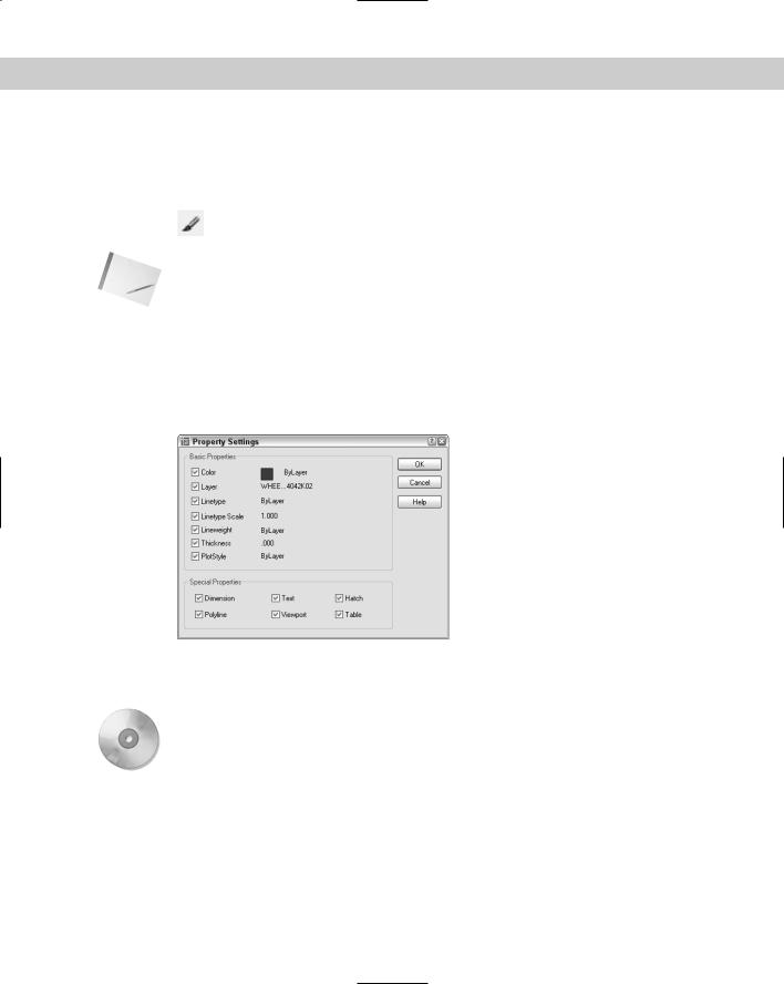
4.If you want to match only some of the object’s properties, right-click and choose Settings to open the Property Settings dialog box, shown in Figure 11-30. Uncheck all the properties you don’t want to match and click OK. The previous prompt returns. Select the object(s) you want to receive the matching properties, that is, the destination objects(s).
On the
CD-ROM
Figure 11-30: The Property Settings dialog box.
5.Press Enter to end object selection and match the properties.
The drawing used in the following Step-by-Step exercise on matching properties, ab11-f. dwg, is in the Drawings folder on the CD-ROM.
STEP-BY-STEP: Matching Properties
1.Open ab11-f.dwg from the CD-ROM.
2.Save the file as ab11-06.dwg in your AutoCAD Bible folder. This is a drawing of a mas- ter-bedroom-suite plan, as shown in Figure 11-31.

272 Part II Drawing in Two Dimensions
3.Pick the wall at 1 in Figure 11-31. Click Match Properties from the Standard toolbar. At the Select destination object(s) or [Settings]: prompt, use a
crossing window to select all the folding closet doors on both sides of the line you just selected. Press Enter to end object selection. This action matches the properties of the doors to the properties of the wall. (The doors turn from gray to black/white.)
4.Pick the text MASTER SUITE. Choose Match Properties from the Standard toolbar. At the
Select destination object(s) or [Settings]: prompt, right-click and choose Settings. In the Property Settings dialog box, deselect all the boxes except Text in the Special Properties section. Click OK.
5.At the Select destination object(s) or [Settings]: prompt, choose the text
CL. in both closets and press Enter to end the command. This action matches the text properties of the text. Notice that the CL. text becomes bold.
6.Save your drawing.
 1
1
Figure 11-31: The master-bedroom-suite plan.
Summary
In this chapter, you read all about layers, colors, linetypes, and lineweights. You learned about:
Using layers to help you organize your drawings by assigning the same properties to related objects
Creating a layer by giving it a name, color, linetype, and lineweight
Changing the layer of existing objects, using the Layer Control drop-down list or the Properties palette
All about layer states — On/Off, Thawed/Frozen, Unlocked/Locked, and Plottable/Not Plottable

Chapter 11 Organizing Drawings with Layers, Colors, Linetypes, and Lineweights |
273 |
Changing the properties of existing layers
Saving sets of layer states and properties and later restoring them
Filtering the layer listing
Purging unused layers and linetypes
Altering the color, linetype, and lineweight of any object
Globally changing the linetype scale, changing the current linetype scale, and changing the object linetype scale of existing objects
Using the DesignCenter to import layers and linetypes from other drawings
Utilizing the Match Properties command to copy properties from one object to one or more destination objects
The next chapter explains how to get detailed information from your drawing.
|
|
|
