

- •Foreword
- •Preface
- •Is This Book for You?
- •How This Book Is Organized
- •How to Use This Book
- •Doing the Exercises
- •Conventions Used in This Book
- •What the Icons Mean
- •About the CD-ROM
- •Other Information
- •Contacting the Author
- •Acknowledgments
- •Contents at a Glance
- •Contents
- •Getting Acquainted with AutoCAD and AutoCAD LT
- •Starting AutoCAD and AutoCAD LT
- •Creating a New Drawing
- •Using the AutoCAD and AutoCAD LT Interface
- •Creating Your First Drawing
- •Saving a Drawing
- •Summary
- •Creating a New Drawing from a Template
- •Working with Templates
- •Opening a Drawing with Default Settings
- •Opening an Existing Drawing
- •Using an Existing Drawing as a Prototype
- •Saving a Drawing Under a New Name
- •Summary
- •The Command Line
- •Command Techniques
- •Of Mice and Pucks
- •Getting Help
- •Summary
- •Typing Coordinates
- •Displaying Coordinates
- •Picking Coordinates on the Screen
- •Locating Points
- •Summary
- •Unit Types
- •Drawing Limits
- •Understanding Scales
- •Inserting a Title Block
- •Common Setup Options
- •The MVSETUP Command
- •Summary
- •Using the LINE Command
- •Drawing Rectangles
- •Drawing Polygons
- •Creating Construction Lines
- •Creating Rays
- •Summary
- •Drawing Circles
- •Drawing Arcs
- •Creating Ellipses and Elliptical Arcs
- •Making Donuts
- •Placing Points
- •Summary
- •Panning
- •The ZOOM Command
- •Aerial View
- •Named Views
- •Tiled Viewports
- •Snap Rotation
- •User Coordinate Systems
- •Isometric Drawing
- •Summary
- •Editing a Drawing
- •Selecting Objects
- •Summary
- •Copying and Moving Objects
- •Using Construction Commands
- •Creating a Revision Cloud
- •Hiding Objects with a Wipeout
- •Double-Clicking to Edit Objects
- •Grips
- •Editing with the Properties Palette
- •Selection Filters
- •Groups
- •Summary
- •Working with Layers
- •Changing Object Color, Linetype, and Lineweight
- •Working with Linetype Scales
- •Importing Layers and Linetypes from Other Drawings
- •Matching Properties
- •Summary
- •Drawing-Level Information
- •Object-Level Information
- •Measurement Commands
- •AutoCAD’s Calculator
- •Summary
- •Creating Single-Line Text
- •Understanding Text Styles
- •Creating Multiline Text
- •Creating Tables
- •Inserting Fields
- •Managing Text
- •Finding Text in Your Drawing
- •Checking Your Spelling
- •Summary
- •Working with Dimensions
- •Drawing Linear Dimensions
- •Drawing Aligned Dimensions
- •Creating Baseline and Continued Dimensions
- •Dimensioning Arcs and Circles
- •Dimensioning Angles
- •Creating Ordinate Dimensions
- •Drawing Leaders
- •Using Quick Dimension
- •Editing Dimensions
- •Summary
- •Understanding Dimension Styles
- •Defining a New Dimension Style
- •Changing Dimension Styles
- •Creating Geometric Tolerances
- •Summary
- •Creating and Editing Polylines
- •Drawing and Editing Splines
- •Creating Regions
- •Creating Boundaries
- •Creating Hatches
- •Creating and Editing Multilines
- •Creating Dlines
- •Using the SKETCH Command
- •Digitizing Drawings with the TABLET Command
- •Summary
- •Preparing a Drawing for Plotting or Printing
- •Creating a Layout in Paper Space
- •Working with Plot Styles
- •Plotting a Drawing
- •Summary
- •Combining Objects into Blocks
- •Inserting Blocks and Files into Drawings
- •Managing Blocks
- •Using Windows Features
- •Working with Attributes
- •Summary
- •Understanding External References
- •Editing an Xref within Your Drawing
- •Controlling Xref Display
- •Managing Xrefs
- •Summary
- •Preparing for Database Connectivity
- •Connecting to Your Database
- •Linking Data to Drawing Objects
- •Creating Labels
- •Querying with the Query Editor
- •Working with Query Files
- •Summary
- •Working with 3D Coordinates
- •Using Elevation and Thickness
- •Working with the User Coordinate System
- •Summary
- •Working with the Standard Viewpoints
- •Using DDVPOINT
- •Working with the Tripod and Compass
- •Getting a Quick Plan View
- •Shading Your Drawing
- •Using 3D Orbit
- •Using Tiled Viewports
- •Defining a Perspective View
- •Laying Out 3D Drawings
- •Summary
- •Drawing Surfaces with 3DFACE
- •Drawing Surfaces with PFACE
- •Creating Polygon Meshes with 3DMESH
- •Drawing Standard 3D Shapes
- •Drawing a Revolved Surface
- •Drawing an Extruded Surface
- •Drawing Ruled Surfaces
- •Drawing Edge Surfaces
- •Summary
- •Drawing Standard Shapes
- •Creating Extruded Solids
- •Drawing Revolved Solids
- •Creating Complex Solids
- •Sectioning and Slicing Solids
- •Using Editing Commands in 3D
- •Editing Solids
- •Listing Solid Properties
- •Summary
- •Understanding Rendering
- •Creating Lights
- •Creating Scenes
- •Working with Materials
- •Using Backgrounds
- •Doing the Final Render
- •Summary
- •Accessing Drawing Components with the DesignCenter
- •Accessing Drawing Content with Tool Palettes
- •Setting Standards for Drawings
- •Organizing Your Drawings
- •Working with Sheet Sets
- •Maintaining Security
- •Keeping Track of Referenced Files
- •Handling Errors and Crashes
- •Managing Drawings from Prior Releases
- •Summary
- •Importing and Exporting Other File Formats
- •Working with Raster Images
- •Pasting, Linking, and Embedding Objects
- •Summary
- •Sending Drawings
- •Opening Drawings from the Web
- •Creating Object Hyperlinks
- •Publishing Drawings
- •Summary
- •Working with Customizable Files
- •Creating Keyboard Shortcuts for Commands
- •Customizing Toolbars
- •Customizing Tool Palettes
- •Summary
- •Creating Macros with Script Files
- •Creating Slide Shows
- •Creating Slide Libraries
- •Summary
- •Creating Linetypes
- •Creating Hatch Patterns
- •Summary
- •Creating Shapes
- •Creating Fonts
- •Summary
- •Working with Menu Files
- •Customizing a Menu
- •Summary
- •Introducing Visual LISP
- •Getting Help in Visual LISP
- •Working with AutoLISP Expressions
- •Using AutoLISP on the Command Line
- •Creating AutoLISP Files
- •Summary
- •Creating Variables
- •Working with AutoCAD Commands
- •Working with Lists
- •Setting Conditions
- •Managing Drawing Objects
- •Getting Input from the User
- •Putting on the Finishing Touches
- •Summary
- •Understanding Local and Global Variables
- •Working with Visual LISP ActiveX Functions
- •Debugging Code
- •Summary
- •Starting to Work with VBA
- •Writing VBA Code
- •Getting User Input
- •Creating Dialog Boxes
- •Modifying Objects
- •Debugging and Trapping Errors
- •Moving to Advanced Programming
- •A Final Word
- •Installing AutoCAD and AutoCAD LT
- •Configuring AutoCAD
- •Starting AutoCAD Your Way
- •Configuring a Plotter
- •System Requirements
- •Using the CD with Microsoft Windows
- •What’s on the CD
- •Troubleshooting
- •Index

Chapter 12 Getting Information from Your Drawing |
285 |
Measurement Commands
The DIVIDE command divides an object into equally spaced sections. The MEASURE command divides an object into sections of a specified length. These commands are useful in many fields — you might need to space bolt holes evenly around the edge of a bushing, or place fence studs along the edge of a plot every 5 feet.
|
Dividing objects |
|
The DIVIDE command divides an object into equal sections. DIVIDE does not break the |
|
object — it simply places point objects along the selected object. You can then use the Node |
|
object snap if you want to draw from those points. |
|
To divide an object, choose Draw Point Divide. Select the object you want to divide. The |
|
command responds with the Enter the number of segments or [Block]: prompt. Type |
|
in the number of segments that you want to create. AutoCAD places the point objects and |
|
ends the command. |
Tip |
Remember that you can set the point display by choosing Format Point Style. An easy-to- |
|
see point style is especially useful for the DIVIDE command. Specify the point style before |
|
using the command. |
|
To create eight segments, for example, you need to place seven point objects. If you have in |
|
your mind the number of point objects you want, add one when specifying the number of |
|
segments. |
|
You can use the Block option to place a block of your choice along the object instead of a |
|
point object. The block must exist in your drawing. (Chapter 18 covers blocks.) If you choose |
|
the Block option (right-click and choose Block), the option responds with the Enter name |
|
of block to insert: prompt. Type the name of the block. The prompt asks, Align block |
|
with object? [Yes/No] <Y>. Answer Y or N depending on whether you want to align the |
|
block with the object. |
Note |
Aligning a block is appropriate for curved objects and blocks that are not completely |
|
symmetrical. |
|
The prompt asks for the number of segments you want, and you type that number, as |
|
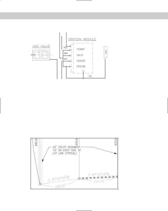
described earlier. Figure 12-11 shows an electrical schematic. Here you want to divide a line |
|
so that you can evenly space wires entering the ignition module. Four wires need to come in |
|
so that the line was divided into five segments, using an easy-to-see point object. |
Measuring objects
The MEASURE command is similar to the DIVIDE command except that you specify the distance between point objects instead of the total number of segments. The command starts measuring from the endpoint closest to where you pick the object. MEASURE does not break the object — it simply places point objects along the object. You can then use the Node object snap if you want to draw from those points.
You can practice using the DIVIDE command after the next section.
286 Part II Drawing in Two Dimensions
Point objects Divided line
Figure 12-11: Dividing a line into five segments by using point objects.
Thanks to Robert Mack of the Dexter Company, Fairfield, Iowa, for this drawing.
To measure an object, choose Draw Point Measure. Select the object you want to measure. The command responds with the Specify length of segment or [Block]: prompt. Type the segment length where you want to place the point objects and end the command.
Remember that you can set the point display by choosing Format Point Style. An easy-to- see point style is especially useful for the MEASURE command. Specify the point style before using the command.
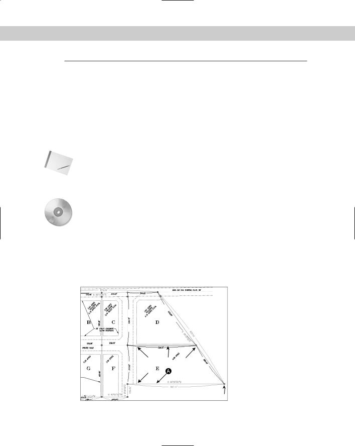
As with the DIVIDE command, you can place a block along the object using the Block option, as long as the block exists in your drawing. The option prompts you for the name of the block and lets you choose if you want to align the block with the object. The prompt asks for the segment length, and you type in the lengths between the points, as described earlier. Figure 12-12 shows a plat drawing with one side of a lot measured into 20-foot segments.
Figure 12-12: Measuring a line into 20-foot segments by using point objects.
Thanks to Bill Maidment of Caltech, Inc. Fairfield, Iowa, for this drawing.

Chapter 12 Getting Information from Your Drawing |
287 |
On the |
The drawing used in the following Step-by-Step exercise on using the DIVIDE and MEASURE |
CD-ROM |
commands, ab12-a.dwg, is in the Drawings folder on the CD-ROM. |
STEP-BY-STEP: Using the DIVIDE and MEASURE Commands
1.Open ab12-a.dwg from the CD-ROM if it isn’t already open from the previous exercise.
2.If you didn’t do the previous exercise, use ZOOM Window to zoom in to the parcels labeled D and E, as shown in Figure 12-13.
3.Choose Format Point Style and choose the fourth style in the first row. Choose Set Size Relative to Screen and set the size to 5%. Click OK.
4. Choose Draw Point Divide. At the Select object to divide: prompt, choose 1 in Figure 12-13. At the Enter the number of segments or [Block]: prompt, type
3 . The command places two points along the line, dividing it into three segments. (If you want, draw lines from the points perpendicular to the opposite side of the parcel to divide it into three parcels.)
5.Choose Draw Point Measure. At the Select object to measure: prompt, choose
2 in Figure 12-13. At the Specify length of segment or [Block]: prompt, type
120 (10 feet). The command places two points along the line.
6.Do not save your drawing. Keep it open if you’re continuing to the next exercise.
2
1
Figure 12-13: The site plan zoomed in to parcels D and E.
AutoCAD’s Calculator
AutoCAD’s calculator is a geometric calculator that not only can calculate numbers like an ordinary calculator but also can calculate points and vectors. The calculator supports object snaps (except apparent intersection, extension, and parallel) and has its own functions so that it’s actually a simple programming language. In fact, you can even use AutoLISP variables in your expressions. Here I show you the basics of the calculator.

288 Part II Drawing in Two Dimensions
To start the calculator, type cal on the command line. If you’re in the middle of a command, type 'cal .
Calculating numbers
Calculating numbers is straightforward and uses standard rules of precedence. The following illustrates this point:
Command: cal
.>> Expression: 3*(2+3)/5-1 2.0
Because the 2+3 sum is in parentheses, it is calculated first so that the expression multiplies 3 by 5 (which is 15), divides it by 5 (which is 3), and subtracts 1 (which is 2).
Using CAL in this way is just like having a handheld calculator by your computer.
When you use CAL transparently, AutoCAD assumes you want the result to be a response to a prompt. Let’s say you want to draw a horizontal line. You know it has to be the total of two other lines whose length you know. Follow the prompts:
Turn on ORTHO.
Start the LINE command.
Specify first point: Pick the start point for the line. Move the cursor to the right to draw at a zero-degree angle and so you can use Direct Distance Entry.
Specify next point or [Undo]: ‘cal >> Expression: 3.953+6.8725 10.8255
End the LINE command. AutoCAD draws a line whose length is the sum of the two numbers.
You can add feet and inches as well. Use the format 6'5" or 6'-5". Don’t put any spaces between the feet and inches. With the calculator, all inches must be marked with a double prime ("), unlike regular AutoCAD command-line usage. (See the sidebar “The ins and outs of fractional inches in CAL.”)
Using coordinates
You can use coordinates in CAL expressions. Coordinates are enclosed in square brackets. Let’s say you want to draw a line that is equal to the length of two other objects in your drawing that you happen to know are 3.953 and 6.8725 units long. You want the line to be at a 20degree angle. At the Specify next point or [Undo]: prompt, start CAL transparently:
>> Expression: [@(3.953+6.8725)<20]
This creates a relative polar coordinate whose length is the sum of two numbers.
Using object snaps
You can use the object snaps as part of CAL expressions. When you press Enter after completing the expression, AutoCAD prompts you for the objects for each object snap in the expression, one after another.

Chapter 12 Getting Information from Your Drawing |
289 |
The ins and outs of fractional inches in CAL
Using fractional inches in CAL expressions is tricky. If you type 3'2-1/2" as a CAL expression, AutoCAD replies Error: Invalid feet’-inches” format. AutoCAD expects a hyphen only between feet and inches. Otherwise, it assumes a hyphen is a minus sign. To write out fractional inches, think of them as little division problems being added to the whole inches. Therefore, if you type the following expression
(3’2”+1”/2”)+(23”+3”/8”)
61.875
AutoCAD takes 3'2" and adds 1" divided by 2" to get 3'2-1/2". Similarly, in the second expression, AutoCAD adds 23" to 3" divided by 8" to get 23-3/8". Yes, it’s slightly awkward. If 3'-2" returns 38.0, as shown below (3' = 36" and 2 more inches is 38"), how do you subtract 2" from 3'?
>> Expression: 3’-2”
38.0
The trick is to put parentheses around the 3 feet so that AutoCAD doesn’t assume the next expression is part of the same feet-inches expression, as shown here:
>> Expression: (3’)-2”
34.0
Here AutoCAD takes the 3 feet (36") and subtracts 2" to get 34.
|
A common use for object snaps in the CAL command is to find the midpoint between two |
|
points. In Figure 12-14, you want to draw a line starting from the midpoint between the cen- |
|
ters of two circles. |
|
To accomplish this, first make sure that OSNAP is off. Then start the LINE command and start |
|
CAL transparently at the Specify first point: prompt. Follow the prompts: |
|
>> Expression: (cen+cen)/2 |
|
>> Select entity for CEN snap: Select the first circle. |
|
>> Select entity for CEN snap: Select the second circle. |
|
(4.86897 7.73008 0.0) |
Tip |
You can now use the new Mid Between 2 Points object snap to find the midpoint between |
|
two points. You can find this object snap on the OSNAP shortcut menu (Shift+right-click). At |
|
the prompts, specify the two points to immediately find their midpoint. For example, you can |
|
use this midpoint as the start or end of a line. |
To calculate the length of a line, use the abs function. (See the list of mathematical functions in Table 12-3.) The following expression shows how this works:
>>Expression: abs(end-end)
>>Select entity for END snap:
>>Select entity for END snap:
61.0
290 Part II Drawing in Two Dimensions
First circle
Midpoint between the circles' centers
Second circle
Figure 12-14: Drawing a line from the midpoint between the centers of the two circles.
You can easily use CAL as a substitute for the From object snap. For example, at the Specify first point: prompt you can enter ' cal and type mid+[3,–2.5] . AutoCAD prompts you for the object for which you want the midpoint and starts the line (3,–2.5) units from there.
Using mathematical functions
CAL supports many mathematical functions typical of a scientific calculator. Table 12-3 lists these functions.
Note A real number is any positive or negative number. Type large numbers without commas. AutoCAD restricts you to integers between –32768 and +32767 but real numbers (numbers with decimal places) can be larger.
Table 12-3: CAL Mathematical Functions
Function |
What It Does |
sin(angle) Calculates the sine of the angle cos(angle) Calculates the cosine of the angle tang(angle) Calculates the tangent of the angle asin(real) Calculates the arc sine of the real number acos(real) Calculates the arc cosine of the real number atan(real) Calculates the arc tangent of the real number

Chapter 12 Getting Information from Your Drawing |
291 |
Function |
What It Does |
|
|
ln(real) |
Calculates the natural log of the real number |
Log(real) |
Calculates the base-10 log of the number |
exp(real) |
Calculates the natural exponent of the real number |
exp10(real) |
Calculates the base-10 exponent of the real number |
sqr(real) |
Calculates the square of the real number |
sqrt(real) |
Calculates the square root of the real number |
abs(real) |
Calculates the absolute value of the real number (the number not including its + or |
|
– sign); also used to calculate lengths |
round(real) |
Rounds the number to its nearest integer |
trunc(real) |
Truncates any decimal value leaving only the integer |
r2d(angle) |
Converts radian angles to degrees |
d2r(angle) |
Converts degree angles to radians |
pi |
Returns the constant pi |
|
|
Using CAL’s special functions
CAL has a set of special functions that you can use to find points. Table 12-4 lists most of these functions and what they do. You can find a complete list in the AutoCAD Command Reference.
|
Table 12-4: Special CAL Functions |
|
|
Function |
What It Does |
|
|
rad |
Gets the radius of the selected object |
cur |
Gets any point that you pick |
@ |
Gets the last point calculated |
vec(p1,p2) |
Calculates the vector from point p1 to point p2 |
vec1(p1,p2) |
Calculates a one-unit vector from point p1 to point p2 |
pld(p1,p2,dist) |
Calculates a point on the line from point p1 to point p2 that is dist units from |
|
point p1; if dist is 0.327, calculates the point 0.327 units from p1 |
plt(p1,p2,t) |
Calculates a point on the line from point p1 to point p2 that is t proportion |
|
from point p1; if t is 0.45, calculates the point 0.45 of the distance from p1 to |
|
p2 (or almost halfway between them) |
dist(p1,p2) |
Calculates the distance between point p1 and point p2 |
dpl(p,p1,p2) |
Calculates the distance from point p to the line from point p1 to point p2 |
Continued
292 Part II Drawing in Two Dimensions
|
|
Table 12-4 (continued) |
|
|
|
|
Function |
What It Does |
|
|
|
|
ang(p1,p2) |
Calculates the angle between the X axis and the line from point p1 to point p2 |
|
ang(v) |
Calculates the angle between the X axis and a vector you define; an example |
|
|
of a vector would be (end-end) where you pick the two endpoints of a line |
|
ang(apex,p1,p2) |
Calculates the angle between the lines from apex to point p1 and apex to |
|
|
point p2; (the apex is the vertex of the angle). |
|
ill(p1,p2,p3,p4) |
Calculates the intersection of two lines from p1 to p2 and from p3 to p4 |
Note |
|
|
A vector is a direction, which is expressed as delta X, delta Y. |
||
Remember that you can specify these points in many ways, most commonly by object snaps. You can use the cur function to pick any point on the screen.
On the |
The drawing used in the following Step-by-Step exercise on using the CAL command, ab12-a. |
CD-ROM |
dwg, is in the Drawings folder on the CD-ROM. |
STEP-BY-STEP: Using the CAL Command (AutoCAD Only)
1.Open ab12-a.dwg from the CD-ROM if you don’t have it open from the previous exercise.
2.Save the drawing as ab12-01.dwg in your AutoCAD Bible folder.
3.If you did not do the previous exercise, use ZOOM Window to zoom in on the parcels labeled D and E, as shown in Figure 12-15.
4 5 2
1
3
Figure 12-15: Parcels D and E in the civil engineering drawing.