

- •Foreword
- •Preface
- •Is This Book for You?
- •How This Book Is Organized
- •How to Use This Book
- •Doing the Exercises
- •Conventions Used in This Book
- •What the Icons Mean
- •About the CD-ROM
- •Other Information
- •Contacting the Author
- •Acknowledgments
- •Contents at a Glance
- •Contents
- •Getting Acquainted with AutoCAD and AutoCAD LT
- •Starting AutoCAD and AutoCAD LT
- •Creating a New Drawing
- •Using the AutoCAD and AutoCAD LT Interface
- •Creating Your First Drawing
- •Saving a Drawing
- •Summary
- •Creating a New Drawing from a Template
- •Working with Templates
- •Opening a Drawing with Default Settings
- •Opening an Existing Drawing
- •Using an Existing Drawing as a Prototype
- •Saving a Drawing Under a New Name
- •Summary
- •The Command Line
- •Command Techniques
- •Of Mice and Pucks
- •Getting Help
- •Summary
- •Typing Coordinates
- •Displaying Coordinates
- •Picking Coordinates on the Screen
- •Locating Points
- •Summary
- •Unit Types
- •Drawing Limits
- •Understanding Scales
- •Inserting a Title Block
- •Common Setup Options
- •The MVSETUP Command
- •Summary
- •Using the LINE Command
- •Drawing Rectangles
- •Drawing Polygons
- •Creating Construction Lines
- •Creating Rays
- •Summary
- •Drawing Circles
- •Drawing Arcs
- •Creating Ellipses and Elliptical Arcs
- •Making Donuts
- •Placing Points
- •Summary
- •Panning
- •The ZOOM Command
- •Aerial View
- •Named Views
- •Tiled Viewports
- •Snap Rotation
- •User Coordinate Systems
- •Isometric Drawing
- •Summary
- •Editing a Drawing
- •Selecting Objects
- •Summary
- •Copying and Moving Objects
- •Using Construction Commands
- •Creating a Revision Cloud
- •Hiding Objects with a Wipeout
- •Double-Clicking to Edit Objects
- •Grips
- •Editing with the Properties Palette
- •Selection Filters
- •Groups
- •Summary
- •Working with Layers
- •Changing Object Color, Linetype, and Lineweight
- •Working with Linetype Scales
- •Importing Layers and Linetypes from Other Drawings
- •Matching Properties
- •Summary
- •Drawing-Level Information
- •Object-Level Information
- •Measurement Commands
- •AutoCAD’s Calculator
- •Summary
- •Creating Single-Line Text
- •Understanding Text Styles
- •Creating Multiline Text
- •Creating Tables
- •Inserting Fields
- •Managing Text
- •Finding Text in Your Drawing
- •Checking Your Spelling
- •Summary
- •Working with Dimensions
- •Drawing Linear Dimensions
- •Drawing Aligned Dimensions
- •Creating Baseline and Continued Dimensions
- •Dimensioning Arcs and Circles
- •Dimensioning Angles
- •Creating Ordinate Dimensions
- •Drawing Leaders
- •Using Quick Dimension
- •Editing Dimensions
- •Summary
- •Understanding Dimension Styles
- •Defining a New Dimension Style
- •Changing Dimension Styles
- •Creating Geometric Tolerances
- •Summary
- •Creating and Editing Polylines
- •Drawing and Editing Splines
- •Creating Regions
- •Creating Boundaries
- •Creating Hatches
- •Creating and Editing Multilines
- •Creating Dlines
- •Using the SKETCH Command
- •Digitizing Drawings with the TABLET Command
- •Summary
- •Preparing a Drawing for Plotting or Printing
- •Creating a Layout in Paper Space
- •Working with Plot Styles
- •Plotting a Drawing
- •Summary
- •Combining Objects into Blocks
- •Inserting Blocks and Files into Drawings
- •Managing Blocks
- •Using Windows Features
- •Working with Attributes
- •Summary
- •Understanding External References
- •Editing an Xref within Your Drawing
- •Controlling Xref Display
- •Managing Xrefs
- •Summary
- •Preparing for Database Connectivity
- •Connecting to Your Database
- •Linking Data to Drawing Objects
- •Creating Labels
- •Querying with the Query Editor
- •Working with Query Files
- •Summary
- •Working with 3D Coordinates
- •Using Elevation and Thickness
- •Working with the User Coordinate System
- •Summary
- •Working with the Standard Viewpoints
- •Using DDVPOINT
- •Working with the Tripod and Compass
- •Getting a Quick Plan View
- •Shading Your Drawing
- •Using 3D Orbit
- •Using Tiled Viewports
- •Defining a Perspective View
- •Laying Out 3D Drawings
- •Summary
- •Drawing Surfaces with 3DFACE
- •Drawing Surfaces with PFACE
- •Creating Polygon Meshes with 3DMESH
- •Drawing Standard 3D Shapes
- •Drawing a Revolved Surface
- •Drawing an Extruded Surface
- •Drawing Ruled Surfaces
- •Drawing Edge Surfaces
- •Summary
- •Drawing Standard Shapes
- •Creating Extruded Solids
- •Drawing Revolved Solids
- •Creating Complex Solids
- •Sectioning and Slicing Solids
- •Using Editing Commands in 3D
- •Editing Solids
- •Listing Solid Properties
- •Summary
- •Understanding Rendering
- •Creating Lights
- •Creating Scenes
- •Working with Materials
- •Using Backgrounds
- •Doing the Final Render
- •Summary
- •Accessing Drawing Components with the DesignCenter
- •Accessing Drawing Content with Tool Palettes
- •Setting Standards for Drawings
- •Organizing Your Drawings
- •Working with Sheet Sets
- •Maintaining Security
- •Keeping Track of Referenced Files
- •Handling Errors and Crashes
- •Managing Drawings from Prior Releases
- •Summary
- •Importing and Exporting Other File Formats
- •Working with Raster Images
- •Pasting, Linking, and Embedding Objects
- •Summary
- •Sending Drawings
- •Opening Drawings from the Web
- •Creating Object Hyperlinks
- •Publishing Drawings
- •Summary
- •Working with Customizable Files
- •Creating Keyboard Shortcuts for Commands
- •Customizing Toolbars
- •Customizing Tool Palettes
- •Summary
- •Creating Macros with Script Files
- •Creating Slide Shows
- •Creating Slide Libraries
- •Summary
- •Creating Linetypes
- •Creating Hatch Patterns
- •Summary
- •Creating Shapes
- •Creating Fonts
- •Summary
- •Working with Menu Files
- •Customizing a Menu
- •Summary
- •Introducing Visual LISP
- •Getting Help in Visual LISP
- •Working with AutoLISP Expressions
- •Using AutoLISP on the Command Line
- •Creating AutoLISP Files
- •Summary
- •Creating Variables
- •Working with AutoCAD Commands
- •Working with Lists
- •Setting Conditions
- •Managing Drawing Objects
- •Getting Input from the User
- •Putting on the Finishing Touches
- •Summary
- •Understanding Local and Global Variables
- •Working with Visual LISP ActiveX Functions
- •Debugging Code
- •Summary
- •Starting to Work with VBA
- •Writing VBA Code
- •Getting User Input
- •Creating Dialog Boxes
- •Modifying Objects
- •Debugging and Trapping Errors
- •Moving to Advanced Programming
- •A Final Word
- •Installing AutoCAD and AutoCAD LT
- •Configuring AutoCAD
- •Starting AutoCAD Your Way
- •Configuring a Plotter
- •System Requirements
- •Using the CD with Microsoft Windows
- •What’s on the CD
- •Troubleshooting
- •Index

Chapter 25 Rendering in 3D 769
5.In the Materials dialog box, choose GREEN GLASS and click Attach. AutoCAD finds the bowl, which has already been attached to the GREEN GLASS material and displays the
Gathering objects...1 found. Select objects to attach “GREEN GLASS” to: prompt. Select the plate on the table and press Enter to return to the dialog box.
6.Click OK to return to your drawing.
7.Save your drawing. Keep it open if you’re continuing to the next Step-by-Step exercise.
Using Backgrounds
AutoCAD offers some sophisticated features for adding backgrounds to your rendering. For example, you can place a picture of the sky in the background. You can also add landscape features such as trees and bushes. This section covers the basics of backgrounds. You have a choice of four types of backgrounds:
Solid places a solid color in the background. You might use solid black for a night scene.
Gradient creates a background of up to three colors in a graded blend.
Image places an image in the background (for example, an image of the sky).
Merge lets you combine your rendering with the image you currently have on your screen.
To create a background, choose Background from the Render toolbar to open the Background dialog box, shown in Figure 25-20.
New |
You can now display backgrounds in your drawing while you draw and edit. (For more infor- |
Feature |
mation, see Chapter 22 for the procedure.) You can even display backgrounds in viewports. |
|
If you choose Solid, you can use the current AutoCAD background (usually white or black) or define a color using the same color controls you use for lights and materials, explained earlier in this chapter. If you choose Gradient, you set separate top, middle, and bottom colors. Click the color swatch of the color you want to work with to set its color. Then use the horizon setting to determine the center of the gradient. The height determines, in percentage form, where the second color starts. For example, 33 percent would create three equal levels of color. If you want only two colors, set the height to 0 (zero). Use Rotation to rotate the gradient.
If you choose Image, use the Image section to specify a file. If you did a full installation (or a custom installation including textures), you have a number of .tga files to choose from in the Textures subfolder of AutoCAD. Of course, you can use your own files. You can use the following file types:
BMP |
JPEG |
TGA |
PNG |
GIF |
PCX |
TIF |
|
Merge uses the current AutoCAD background (usually solid white or black) as the background for the rendering. It doesn’t require any settings.
770 Part IV Drawing in Three Dimensions
Figure 25-20: The Background dialog box.
You can choose an additional file in the Environment section (at the bottom of the dialog box) to create reflection and refraction effects. You can use the same types of files for environment as for images. AutoCAD maps the image onto a sphere surrounding the scene.
On the |
The drawing used in the following Step-by-Step exercise on adding a background, ab25-06. |
CD-ROM |
dwg, is in the Results folder on the CD-ROM. The graphic file, sky.gif, which you may or |
|
may not need, is in the Drawings folder on the CD-ROM. See the instructions in the exercise. |
STEP-BY-STEP: Adding a Background
1.If you have ab25-06.dwg open, use it. Otherwise, open it from your AutoCAD Bible folder if you did the previous exercise or from the Results folder of the CD-ROM.
2.Save the file as ab25-07.dwg in your AutoCAD Bible folder.
3.If you did a full AutoCAD installation or a custom installation including the textures, choose Background from the Render toolbar. If not, find sky.gif on the CD-ROM and copy it to AutoCAD’s Support subfolder. Then choose Background from the Render toolbar.
4.Choose Image at the top of the Background dialog box.
5.In the Image section, choose Find File.
6.Open the Textures folder (to locate this folder, choose Tools Options, click the Files tab, and double-click the Texture Maps Search Path) and choose sky.tga (make sure the Files of Type drop-down list box says *.tga) or choose sky.gif from AutoCAD’s Support subfolder. Click Open.
7.Click Preview. AutoCAD displays the file.
8.Click OK. You won’t see the result until you render the drawing.
9.Save your drawing. If you’re continuing to the next Step-by-Step exercise, keep the drawing open.
Chapter 25 Rendering in 3D 771
Foggy landscapes
The landscape commands enable you to create and edit landscapes. AutoCAD comes with a small library of trees, bushes, people, and a DO NOT ENTER road sign. Choose Landscape New from the Render toolbar, choose an item, and preview it. When you find one that you like, set the geometry. Single Face results in quicker rendering than Crossing Faces but is less realistic. Choose View Aligned if you want the object to always face the viewer, like a tree. You might uncheck this for the road sign — you don’t want the sign to face the viewer from both directions. Set the height (usually in inches) and click Position to place it in your drawing.
Note: When you place the landscape object, it appears as a triangle or a rectangle. You don’t see the object until you render the view. Choose Landscape Edit to edit the characteristics of an existing landscape object. Choose Landscape Library to edit, delete, and add landscape objects.
Choose Fog from the Render toolbar to open the Fog/Depth Cue dialog box. Fog is used to give a sense of distance because objects in the distance often do not appear to be as clear as those close up. Choose Enable Fog to turn fog on. You set the color, near and far distances (where the fog starts and ends), and near and far percentages of fog (how much fog there should be at the near and far distances).
Doing the Final Render
You’re finally ready to render. Preparing to render can be a long process. If you want, you can choose Render Preferences from the Render toolbar first to open the Rendering
Preferences dialog box. This dialog box is an exact copy of the Render dialog box and lets you preset the rendering settings. However, you can also make all these settings in the Render dialog box.
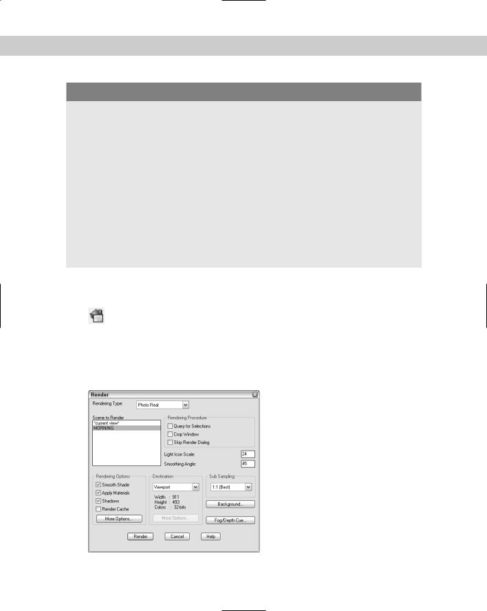
To render, choose Render from the Render toolbar. This opens the Render dialog box, shown in Figure 25-21.
Figure 25-21: The Render dialog box.

772 Part IV Drawing in Three Dimensions
This dialog box has the following components:
From the Rendering Type drop-down list, choose the type of rendering you want.
In the Scene to Render box, choose a scene.
In the Rendering Procedure section, check one of the options if you want. Query for Selections means that AutoCAD asks you to select objects. Use this to test a rendering on one or more objects. Choose Crop Window to choose a window to render. Choose Skip Render Dialog to render immediately without even opening the dialog box (the next time) — choose Render Preferences on the Render toolbar to change this option when you want the Render dialog box back again.
Set the light icon scale. Use the drawing scale factor for this.
Set the smoothing angle. The smoothing angle determines the angle at which AutoCAD assumes an edge as opposed to a smooth curve. The default is 45 degrees. A lower angle would result in more edges.
In the Rendering Options section, check Smooth Shade to smooth out a multi-edged object. AutoCAD blends colors across adjacent faces.
Check Apply Materials to use the materials you imported and attached.
Check Shadows to generate shadows. You can only create shadows with the Photo Real and Photo Raytrace rendering types.
Check Render Cache to save rendering information in a file. AutoCAD can reuse this information for subsequent renderings, saving time.
Click More Options to open a dialog box that varies with the type of rendering. Usually, you can use the defaults, but you can click Help to get an explanation of each item.
In the Destination section, choose where you want the rendering to appear. The default is Viewport. If you have one viewport, the rendering covers the entire drawing area. If you’re using several viewports, the rendering appears in the active viewport. You can also render to the render window. The render window is a regular Microsoft Windows window that lets you copy the rendering to the Clipboard or save the rendering as a bitmap (.bmp) file. Finally, you can save the rendering directly to a file.
Use the Sub Sampling drop-down list to set the sampling of pixels that AutoCAD renders. The default is 1:1, which means all the pixels are rendered. You can speed up the rendering by choosing another ratio.
The Render dialog box has buttons to take you to the Background and Fog/Depth Cue dialog boxes if you decide at the last minute that you want to use these features.
When you’ve finished the settings, click Render to render the drawing.
On the |
The drawing used in the following Step-by-Step exercise on creating a final rendering, |
CD-ROM |
ab25-07.dwg, is in the Results folder on the CD-ROM. |
STEP-BY-STEP: Creating a Final Rendering
1.If you have ab25-07.dwg open, use it. Otherwise, open it from your AutoCAD Bible folder if you did the previous exercise or from the Results folder of the CD-ROM.
2.Save the file as ab25-08.dwg in your AutoCAD Bible folder.
Chapter 25 Rendering in 3D 773
3.Choose Lights from the Render toolbar. In the Lights box, choose P1 and click Modify. Change the intensity to 200 and click OK twice to return to your drawing. This is the type of adjustment you often make when doing the final rendering.
4.Choose Render from the Render toolbar.
5.Make sure that Rendering Type is set to Photo Real.
6.Set Scene to Render to MORNING. Check Shadows.
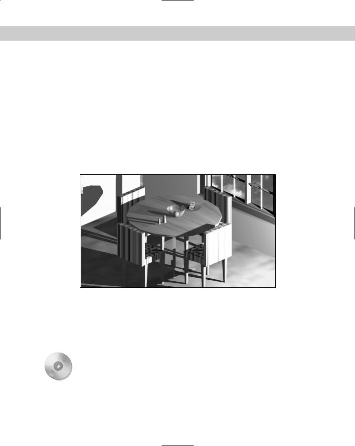
7.Click Render. Wait until AutoCAD finishes the rendering. Look at those shadows! Look at the transparent green bowl with the orange in it. Note the sky image outside the window. Okay, so the pink marble is a bit gaudy.
8.To get rid of the ugly UCS icon, choose View Display UCS Icon On.
9.The rendering should look like Figure 25-22, only a lot better because you see it in color on your screen. Save your drawing.
Figure 25-22: The final rendering with shadows, transparent objects, and a background.
Thanks to Autodesk for the sky.gif file. This material has been reprinted with permission from and under the copyright of Autodesk, Inc.
Remember that rendering is a trial-and-error process. Don’t expect to get it right the first time. You can probably see several areas for improvement. At this point, you would go back and tweak the lights, materials, and so on until you were satisfied.
On the |
AccuRender is a rendering program that offers additional rendering capabilities. Look for it in |
CD-ROM |
Software\Chap25\AccuRender. |
774 Part IV Drawing in Three Dimensions
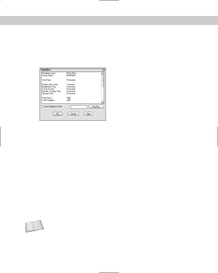
Statistics
Choose Statistics on the Render toolbar to open a window that lists statistics relating to your rendering. You can save these to a file. This information is very helpful if you can’t remember which rendering type you used or if you want to compare the time it takes to render a scene using different options. Figure 25-23 shows an example.
Figure 25-23: A statistics listing of a rendering.
Saving rendered images
You can save your rendered images and redisplay them at another time. You can also use saved rendered images in other applications and print them from those applications. After rendering to a viewport, choose Tools Display Image Save. In the Save Image dialog box, choose the file type .bmp, .tga, or .tif.
You can change the size and placement (offset) of the image or accept the defaults. Click OK. AutoCAD opens the Image File dialog box so that you can specify a filename. After selecting a file, click OK again.
After rendering to a render window, choose File Save from that window’s menu and enter a filename. Click OK. AutoCAD saves the image as a .bmp (bitmap) file.
To redisplay a rendered image, choose Tools Display Image View. Choose the file and click Open in the Replay dialog box. You have the opportunity to crop the image or you can accept the original size. AutoCAD displays the image. Do a regen to return to your regular drawing display.
You can import these saved rendered images back into your drawing. Figure 25-24 shows three floating viewports. One of the views shows the rendered image.
Cross- |
See Chapter 27 for detailed instructions on importing images. You can plot rendered view- |
Reference |
ports, as I explain in Chapter 17. |
|